
Setup and Quick Reference Guide
Page 5
6 Finding Information 57 7 Getting Help 59 Obtaining Assistance 59 Fast Call for Help 60 Loading iAMT drivers on installation 60 Technical Support and Customer Service . . . . . 61 DellConnect 61 Online Services 61 AutoTech Service 62 Automated Order-Status Service 62 Problems With Your Order 62 Product Information 63 Returning Items for Warranty Repair or Credit . . . . . 63 Before You Call 64 Contacting Dell 66 Index 67 Contents 5
6 Finding Information 57 7 Getting Help 59 Obtaining Assistance 59 Fast Call for Help 60 Loading iAMT drivers on installation 60 Technical Support and Customer Service . . . . . 61 DellConnect 61 Online Services 61 AutoTech Service 62 Automated Order-Status Service 62 Problems With Your Order 62 Product Information 63 Returning Items for Warranty Repair or Credit . . . . . 63 Before You Call 64 Contacting Dell 66 Index 67 Contents 5

Setup and Quick Reference Guide
Page 17
... be fully functional. Setting Up Your Computer Quick Setup CAUTION: Before you did not order them. 1 Your computer comes with your computer. Setting Up Your Computer 17 NOTE: Some devices may require an optional adapter to connect to the Dell Technology Guide for video may not be available during boot or when running DOS. Refer to older monitors which only support VGA and/or DVI...
... be fully functional. Setting Up Your Computer Quick Setup CAUTION: Before you did not order them. 1 Your computer comes with your computer. Setting Up Your Computer 17 NOTE: Some devices may require an optional adapter to connect to the Dell Technology Guide for video may not be available during boot or when running DOS. Refer to older monitors which only support VGA and/or DVI...

Setup and Quick Reference Guide
Page 18
Alternatively you may use the VGA port to connect a display device if the PCI-Express card is not a valid configuration. Remove the PCI-Express card. NOTE: Connection of a DisplayPort monitor or adapter will result in the x16 PCI-Express slot being disabled. This is not a graphics card. 3 Connect the monitor using a VGA cable. 4 Connect a USB device, such as a keyboard or mouse. 18 Setting Up Your Computer
Alternatively you may use the VGA port to connect a display device if the PCI-Express card is not a valid configuration. Remove the PCI-Express card. NOTE: Connection of a DisplayPort monitor or adapter will result in the x16 PCI-Express slot being disabled. This is not a graphics card. 3 Connect the monitor using a VGA cable. 4 Connect a USB device, such as a keyboard or mouse. 18 Setting Up Your Computer
Setup and Quick Reference Guide
Page 43
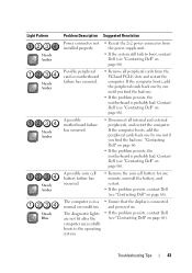
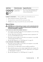
... cell battery failure has occurred. • Remove the coin cell battery for one minute, reinstall the battery, and restart. • If the problem persists, contact Dell (see "Contacting Dell" on page 66). Troubleshooting Tips 43 Light Pattern Steady Amber Steady Amber Steady Amber Steady Amber Steady Blue Problem Description Suggested Resolution Power connector not installed properly. • Reseat the 2x2 power connector from the PCI and PCI-E slots and...
... cell battery failure has occurred. • Remove the coin cell battery for one minute, reinstall the battery, and restart. • If the problem persists, contact Dell (see "Contacting Dell" on page 66). Troubleshooting Tips 43 Light Pattern Steady Amber Steady Amber Steady Amber Steady Amber Steady Blue Problem Description Suggested Resolution Power connector not installed properly. • Reseat the 2x2 power connector from the PCI and PCI-E slots and...
Setup and Quick Reference Guide
Page 44
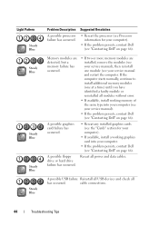
... available, install working graphics card into your computer (see your service manual and restart the computer. A possible USB failure Reinstall all USB devices and check all has occurred. drive or hard drive failure has occurred. Light Pattern Steady Blue Steady Blue Steady Blue Steady Blue Steady Blue Problem Description A possible processor failure has occurred. Memory modules are detected, but a memory failure has occurred. • If two or more memory modules are installed, remove the...
... available, install working graphics card into your computer (see your service manual and restart the computer. A possible USB failure Reinstall all USB devices and check all has occurred. drive or hard drive failure has occurred. Light Pattern Steady Blue Steady Blue Steady Blue Steady Blue Steady Blue Problem Description A possible processor failure has occurred. Memory modules are detected, but a memory failure has occurred. • If two or more memory modules are installed, remove the...

Setup and Quick Reference Guide
Page 45
..., install working memory of the same type into your computer (see your service manual). • If the problem persists, contact Dell (see "Contacting Dell" on page 66). Light Pattern Steady Blue Steady Blue Problem Description Suggested Resolution No memory modules are detected. • If two or more memory modules are using is supported by your computer (see the "Specifications" section for your service manual) and restart the computer. Troubleshooting...
..., install working memory of the same type into your computer (see your service manual). • If the problem persists, contact Dell (see "Contacting Dell" on page 66). Light Pattern Steady Blue Steady Blue Problem Description Suggested Resolution No memory modules are detected. • If two or more memory modules are using is supported by your computer (see the "Specifications" section for your service manual) and restart the computer. Troubleshooting...
Setup and Quick Reference Guide
Page 46
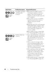
... make sure it is functioning properly. • If the operating system is attempting to the system board (see the "System Board Components" section for your computer). • If there is an error message on page 66). 46 Troubleshooting Tips Another failure has occurred. • Ensure that all hard drive and optical drive cables are properly connected to boot from the computer for each expansion card installed...
... make sure it is functioning properly. • If the operating system is attempting to the system board (see the "System Board Components" section for your computer). • If there is an error message on page 66). 46 Troubleshooting Tips Another failure has occurred. • Ensure that all hard drive and optical drive cables are properly connected to boot from the computer for each expansion card installed...
Setup and Quick Reference Guide
Page 47
... you are : • Power, keyboard, and mouse extension cables • Too many devices connected to the same power strip • Multiple power strips connected to resume normal operation. For more information about the type of interference are not using is supported by your computer is in standby mode. Light Pattern Blinking Blue Problem Description The computer is successfully communicating with the memory. • Run the Dell Diagnostics (see www.dell.com/regulatory_compliance.
... you are : • Power, keyboard, and mouse extension cables • Too many devices connected to the same power strip • Multiple power strips connected to resume normal operation. For more information about the type of interference are not using is supported by your computer is in standby mode. Light Pattern Blinking Blue Problem Description The computer is successfully communicating with the memory. • Run the Dell Diagnostics (see www.dell.com/regulatory_compliance.

Setup and Quick Reference Guide
Page 52
... to a Previous Device Driver Version 1 Click the Windows Vista Start button , and right-click Computer. 2 Click Properties→ Device Manager. otherwise, contact your first time using the Drivers and Utilities media, try the following: • Windows Device Driver Rollback (see "Returning to the operating state that existed before you see "Restoring Your Operating System" on the screen. Returning to enter the Device Manager. 3 Right-click the device for which the new driver was installed and click...
... to a Previous Device Driver Version 1 Click the Windows Vista Start button , and right-click Computer. 2 Click Properties→ Device Manager. otherwise, contact your first time using the Drivers and Utilities media, try the following: • Windows Device Driver Rollback (see "Returning to the operating state that existed before you see "Restoring Your Operating System" on the screen. Returning to enter the Device Manager. 3 Right-click the device for which the new driver was installed and click...

Setup and Quick Reference Guide
Page 53
... are installing the driver (for which you want to reinstall and follow the instructions on the computer, click Continue; 5 At the Welcome Dell System Owner screen, click Next. Manually Reinstalling Drivers 1 Click the Windows Vista Start button , and right-click Computer. 2 Click Properties→ Device Manager. Restoring Your Operating System You can restore your operating system in your administrator to enter the Device Manager. 3 Double-click the type of device for example, Audio or Video...
... are installing the driver (for which you want to reinstall and follow the instructions on the computer, click Continue; 5 At the Welcome Dell System Owner screen, click Next. Manually Reinstalling Drivers 1 Click the Windows Vista Start button , and right-click Computer. 2 Click Properties→ Device Manager. Restoring Your Operating System You can restore your operating system in your administrator to enter the Device Manager. 3 Double-click the type of device for example, Audio or Video...
Setup and Quick Reference Guide
Page 57
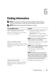
... Service Code The Service Tag/Express Service Code is located on your computer. • Use the Service Tag to identify your computer when you use support.dell.com or contact support. • Enter the Express Service Code to direct your call when contacting support NOTE: Your Service Tag/Express Service Code is located on your media to provide last-minute updates about technical changes to your computer. Drivers and Utilities Media • A diagnostic program for technicians or experienced users...
... Service Code The Service Tag/Express Service Code is located on your computer. • Use the Service Tag to identify your computer when you use support.dell.com or contact support. • Enter the Express Service Code to direct your call when contacting support NOTE: Your Service Tag/Express Service Code is located on your media to provide last-minute updates about technical changes to your computer. Drivers and Utilities Media • A diagnostic program for technicians or experienced users...

Setup and Quick Reference Guide
Page 69
..., 58 Service Manual, 58 Service Tag, 57 setup computer, 17 installing your computer in an enclosure, 22 Internet, 24 quick setup, 17 software problems, 48 reinstalling, 51 troubleshooting, 48-49 updates, 49 specifications all, 29 audio, 30 connectors, 33 controls and lights, 34 drives, 32 environmental, 37 expansion bus, 30 memory, 29 physical, 36 power, 35 processor, 29 system information, 29 video, 30 support, 59 contacting Dell, 66 DellConnect, 61 support (continued) online services, 61...
..., 58 Service Manual, 58 Service Tag, 57 setup computer, 17 installing your computer in an enclosure, 22 Internet, 24 quick setup, 17 software problems, 48 reinstalling, 51 troubleshooting, 48-49 updates, 49 specifications all, 29 audio, 30 connectors, 33 controls and lights, 34 drives, 32 environmental, 37 expansion bus, 30 memory, 29 physical, 36 power, 35 processor, 29 system information, 29 video, 30 support, 59 contacting Dell, 66 DellConnect, 61 support (continued) online services, 61...
Setup and Features Information Tech Sheet
Page 4
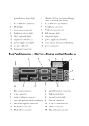
...cable slot 19 back panel connectors 2 slimline flex bay (for optional wireless connector 8 line-out connector 9 line-in/microphone connector 10 USB 2.0 connectors (6) 11 VGA video connector 12 eSATA connector 13 DisplayPort connector 14 PS2 keyboard connector Mini Tower, Desktop, and Small Form Factor 1 2 3 4 5 6 7 8 9 14 13 12 11 10 1 PS2 mouse connector 2 parallel (printer) connector 3 serial connector 4 link integrity light 5 network adapter connector 6 network activity light 7 space for optional floppy drive or memory card reader) 4 CD/DVD drive eject button...
...cable slot 19 back panel connectors 2 slimline flex bay (for optional wireless connector 8 line-out connector 9 line-in/microphone connector 10 USB 2.0 connectors (6) 11 VGA video connector 12 eSATA connector 13 DisplayPort connector 14 PS2 keyboard connector Mini Tower, Desktop, and Small Form Factor 1 2 3 4 5 6 7 8 9 14 13 12 11 10 1 PS2 mouse connector 2 parallel (printer) connector 3 serial connector 4 link integrity light 5 network adapter connector 6 network activity light 7 space for optional floppy drive or memory card reader) 4 CD/DVD drive eject button...

Setup and Features Information Tech Sheet
Page 6
f DVI to DisplayPort connector. 2 Connect a USB device, such as a keyboard or mouse. 3 Connect the network cable (optional). 4 Connect the modem (optional). 5 Connect the power cable(s). e The DisplayPort cable.
f DVI to DisplayPort connector. 2 Connect a USB device, such as a keyboard or mouse. 3 Connect the network cable (optional). 4 Connect the modem (optional). 5 Connect the power cable(s). e The DisplayPort cable.

Dell™ OptiPlex™ 960 System Board Mode Configuration
Page 2
... system documentation on support.dell.com. 4 Replace the computer cover. Other trademarks and trade names may not operate as it down . 9 Reconnect any proprietary interest in this document is strictly forbidden. disclaims any USB mass storage devices (such as hard drives or flash keys). 6 Disconnect the network cable. 7 Turn the computer on the label. When the initialization screen appears, enter the mode number you cannot change without the written...
... system documentation on support.dell.com. 4 Replace the computer cover. Other trademarks and trade names may not operate as it down . 9 Reconnect any proprietary interest in this document is strictly forbidden. disclaims any USB mass storage devices (such as hard drives or flash keys). 6 Disconnect the network cable. 7 Turn the computer on the label. When the initialization screen appears, enter the mode number you cannot change without the written...

Technology Guide
Page 5
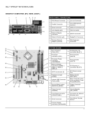
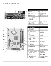
... Light 11 VGA Connector 5 Network Adapter Connector 12 eSATA Connector 6 Network Activity Light 13 DisplayPort Connector 7 Wireless Network Adapter (optional) 14 PS/2 Keyboard Connector SYSTEM BOARD 1 Wireless Card Connector 12 SATA Drive Connectors (4) 2 Thermal Sensor Connector 13 Internal USB Flex Bay Connector 3 Internal Speaker Connector (INT SPKR1) 14 BIOS/RTC Reset Jumper Pins 4 Fan (FAN_CPU) Intrusion Switch 15 Connector (INTRUDER) 5 Processor Connector (CPU) 16 PCI Express x16 Connector (SLOT1) Processor Power 6 Connector (12VPOWER) 17 PCI Connector...
... Light 11 VGA Connector 5 Network Adapter Connector 12 eSATA Connector 6 Network Activity Light 13 DisplayPort Connector 7 Wireless Network Adapter (optional) 14 PS/2 Keyboard Connector SYSTEM BOARD 1 Wireless Card Connector 12 SATA Drive Connectors (4) 2 Thermal Sensor Connector 13 Internal USB Flex Bay Connector 3 Internal Speaker Connector (INT SPKR1) 14 BIOS/RTC Reset Jumper Pins 4 Fan (FAN_CPU) Intrusion Switch 15 Connector (INTRUDER) 5 Processor Connector (CPU) 16 PCI Express x16 Connector (SLOT1) Processor Power 6 Connector (12VPOWER) 17 PCI Connector...
Technology Guide
Page 7
...7 Wireless Network Adapter (optional) 14 PS/2 Keyboard Connector SYSTEM BOARD 1 Fan Connector (FAN_CPU) 13 PCI Express x16 Connector (SLOT1) 2 Processor Connector (CPU) 14 PCI Connector (SLOT2) Processor Power 3 Connector (12VPOWER) Memory Module 4 Connectors (DIMM_1, DIMM_2, DIMM_3, DIMM_4) 5 SATA Connectors (3) 6 Password Jumper (PSWD) 7 Internal USB Connector (FLEX_USB) 15 PCI Connector (SLOT3) 16 PCI Express x1 Connector (SLOT4) 17 RTC Reset Jumper Pins 18 Battery Socket (BATTERY) Riser Connector (uses 19 PCI-E port/SLOT1 and PCI port/SLOT2) 8 Service Mode...
...7 Wireless Network Adapter (optional) 14 PS/2 Keyboard Connector SYSTEM BOARD 1 Fan Connector (FAN_CPU) 13 PCI Express x16 Connector (SLOT1) 2 Processor Connector (CPU) 14 PCI Connector (SLOT2) Processor Power 3 Connector (12VPOWER) Memory Module 4 Connectors (DIMM_1, DIMM_2, DIMM_3, DIMM_4) 5 SATA Connectors (3) 6 Password Jumper (PSWD) 7 Internal USB Connector (FLEX_USB) 15 PCI Connector (SLOT3) 16 PCI Express x1 Connector (SLOT4) 17 RTC Reset Jumper Pins 18 Battery Socket (BATTERY) Riser Connector (uses 19 PCI-E port/SLOT1 and PCI port/SLOT2) 8 Service Mode...
Technology Guide
Page 9
...VGA Connector 12 eSATA Connector 13 DisplayPort Connector 7 Wireless Network Adapter (optional) 14 PS/2 Keyboard Connector SYSTEM BOARD 1 Fan Connector (FAN_CPU) 2 Processor Connector (CPU) Processor Power 3 Connector (12VPOWER) Memory Module 4 Connectors (DIMM_1, DIMM_2, DIMM_3, DIMM_4) 12 Serial Port Connector Intrusion Switch 13 Connector (INTRUDER) Front Panel Thermal 14 Sensor Cable Connector 15 Real Time Clock Reset (RTCRST) 5 Password Jumper Pins (PSWD) 16 PCI Express x16 Connector (SLOT1) 6 SATA Drive Connectors (3) 7 Internal (FlexBay) USB Connector 17 PCI...
...VGA Connector 12 eSATA Connector 13 DisplayPort Connector 7 Wireless Network Adapter (optional) 14 PS/2 Keyboard Connector SYSTEM BOARD 1 Fan Connector (FAN_CPU) 2 Processor Connector (CPU) Processor Power 3 Connector (12VPOWER) Memory Module 4 Connectors (DIMM_1, DIMM_2, DIMM_3, DIMM_4) 12 Serial Port Connector Intrusion Switch 13 Connector (INTRUDER) Front Panel Thermal 14 Sensor Cable Connector 15 Real Time Clock Reset (RTCRST) 5 Password Jumper Pins (PSWD) 16 PCI Express x16 Connector (SLOT1) 6 SATA Drive Connectors (3) 7 Internal (FlexBay) USB Connector 17 PCI...
Technology Guide
Page 16
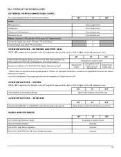
... WIRELESS Internal Intel 5300 802.11 draft-N WiFi (with optional riser. DELL™ OPTIPLEX™ 960 TECHNICAL GUIDE EXTERNAL PORTS/CONNECTORS (CONT.) See chassis diagrams section for port/connector locations Audio: Microphone-in Headphone Stereo line-in/microphone Speakers line out Risers: (replaces 1 PCI slot and 1 PCIe slot on DT system board) Combo full height riser with 1 PCI and 1 PCIe connector Dual full height riser with optional riser Supports low profile card 1 This term does not connote an actual operating speed...
... WIRELESS Internal Intel 5300 802.11 draft-N WiFi (with optional riser. DELL™ OPTIPLEX™ 960 TECHNICAL GUIDE EXTERNAL PORTS/CONNECTORS (CONT.) See chassis diagrams section for port/connector locations Audio: Microphone-in Headphone Stereo line-in/microphone Speakers line out Risers: (replaces 1 PCI slot and 1 PCIe slot on DT system board) Combo full height riser with 1 PCI and 1 PCIe connector Dual full height riser with optional riser Supports low profile card 1 This term does not connote an actual operating speed...

Technology Guide
Page 36
DELL™ OPTIPLEX™ 960 TECHNICAL GUIDE BIOS DEFAULTS Drives BIOS Factory Defaults (All chassis unless noted) Diskette drive: USB SATA-0: SATA-1: SATA-2: SATA-31: External SATA: Enable Enable Enable Enable Enable SATA Operation: RAID On SMART Reporting: Disable Onboard Devices Integrated NIC: Integrated Audio: USB Controller: Rear Quad USB: Rear Dual USB: Front USB: PCI Slots: LPT Port Mode: Serial Port #1: Enable Enable Enable Enable Enable Enable Enable PS/2 Auto Video Primary Video: Auto Performance Multiple CPU Core: SpeedStep: HDD Acoustic Mode: Enable Disable, ...
DELL™ OPTIPLEX™ 960 TECHNICAL GUIDE BIOS DEFAULTS Drives BIOS Factory Defaults (All chassis unless noted) Diskette drive: USB SATA-0: SATA-1: SATA-2: SATA-31: External SATA: Enable Enable Enable Enable Enable SATA Operation: RAID On SMART Reporting: Disable Onboard Devices Integrated NIC: Integrated Audio: USB Controller: Rear Quad USB: Rear Dual USB: Front USB: PCI Slots: LPT Port Mode: Serial Port #1: Enable Enable Enable Enable Enable Enable Enable PS/2 Auto Video Primary Video: Auto Performance Multiple CPU Core: SpeedStep: HDD Acoustic Mode: Enable Disable, ...


