User Manual
Page 2
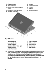
contactless smart card reader 17. touchpad buttons (2) 18. Back View 1. power and battery status lights 5. audio connector 10. Fan noise is running. Secure Digital (SD) memory-card reader 16. trackstick 21. power connector 6. Restricting the airflow can ... such as a closed briefcase, while it is normal and does not indicate a problem with the fan or the computer. 2 VGA connector 9. Do not store your Dell computer in the air vents. network connector 7. device status lights Figure 2. The computer turns on the fan when the computer gets hot. fingerprint reader 15...
contactless smart card reader 17. touchpad buttons (2) 18. Back View 1. power and battery status lights 5. audio connector 10. Fan noise is running. Secure Digital (SD) memory-card reader 16. trackstick 21. power connector 6. Restricting the airflow can ... such as a closed briefcase, while it is normal and does not indicate a problem with the fan or the computer. 2 VGA connector 9. Do not store your Dell computer in the air vents. network connector 7. device status lights Figure 2. The computer turns on the fan when the computer gets hot. fingerprint reader 15...
User Manual
Page 4
...modem connector 4. USB 2.0 connector 9. Do not store your computer. Fan noise is running. WARNING: The AC adapter works with your Dell computer in the air vents. However, power connectors and power strips vary among countries. Back View 1. smart card slot WARNING: Do...equipment damage. 4 Figure 4. power connector 6. Restricting the airflow can damage the computer or cause a fire. VGA connector 8. power and battery status lights 5. audio connector 10. Quick Setup WARNING: Before you begin any of the procedures in this section, read the safety information that...
...modem connector 4. USB 2.0 connector 9. Do not store your computer. Fan noise is running. WARNING: The AC adapter works with your Dell computer in the air vents. However, power connectors and power strips vary among countries. Back View 1. smart card slot WARNING: Do...equipment damage. 4 Figure 4. power connector 6. Restricting the airflow can damage the computer or cause a fire. VGA connector 8. power and battery status lights 5. audio connector 10. Quick Setup WARNING: Before you begin any of the procedures in this section, read the safety information that...
User Manual
Page 7
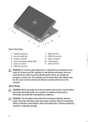
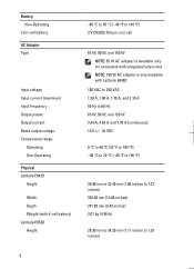
Memory Memory connector Memory capacity Memory type Minimum memory Maximum memory Battery Type Dimensions: 4-cell and 6-cell Depth Height Width 9-cell Depth Height Width Weight: 4-cell 6-cell 9-cell Voltage: 4-cell 6-cell and 9-cell Temperature range: Operating two ...
Memory Memory connector Memory capacity Memory type Minimum memory Maximum memory Battery Type Dimensions: 4-cell and 6-cell Depth Height Width 9-cell Depth Height Width Weight: 4-cell 6-cell 9-cell Voltage: 4-cell 6-cell and 9-cell Temperature range: Operating two ...
User Manual
Page 8
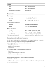
... Input voltage Input current (maximum) Input frequency Output power Output current Rated output voltage Temperature range: Operating Non-Operating Physical Latitude E6420 Height Width Depth Weight (with 4-cell battery) Latitude E6520 Height -40 °C to 65 °C (-40 °F to 1.35 inches) 8 NOTE: 150 W ...AC adapter is available only for computers with Latitude E6420. 100 VAC to 240 VAC 1.50 A, 1.60 A, 1.70 A, and 2.10 A 50 Hz to 60 Hz 65 W, 90 W, and...
... Input voltage Input current (maximum) Input frequency Output power Output current Rated output voltage Temperature range: Operating Non-Operating Physical Latitude E6420 Height Width Depth Weight (with 4-cell battery) Latitude E6520 Height -40 °C to 65 °C (-40 °F to 1.35 inches) 8 NOTE: 150 W ...AC adapter is available only for computers with Latitude E6420. 100 VAC to 240 VAC 1.50 A, 1.60 A, 1.70 A, and 2.10 A 50 Hz to 60 Hz 65 W, 90 W, and...
User Manual
Page 9
...Width Depth Weight (with your computer and the regulatory compliance website at www.dell.com/ regulatory_compliance for more information on: • Safety best practices • Regulatory certification • Ergonomics See www.dell.com for additional information on: • Warranty • Terms and ...Conditions (U.S. All rights reserved. S71.04-1985 Finding More Information and Resources See the safety and regulatory documents that shipped with 4-cell battery) 384.00 mm (15....
...Width Depth Weight (with your computer and the regulatory compliance website at www.dell.com/ regulatory_compliance for more information on: • Safety best practices • Regulatory certification • Ergonomics See www.dell.com for additional information on: • Warranty • Terms and ...Conditions (U.S. All rights reserved. S71.04-1985 Finding More Information and Resources See the safety and regulatory documents that shipped with 4-cell battery) 384.00 mm (15....

Owners Manual
Page 3
... Connector Plug 17 Removing the Modem Connector Plug 17 Installing the Modem Connector Plug 18 5 ExpressCard 19 Removing the ExpressCard 19 Installing the ExpressCard 19 6 Battery...21 Removing the Battery...21 Installing the Battery...22 7 Subscriber Identity Module (SIM) Card 23 Removing the Subscriber Identity Module (SIM) Card 23
... Connector Plug 17 Removing the Modem Connector Plug 17 Installing the Modem Connector Plug 18 5 ExpressCard 19 Removing the ExpressCard 19 Installing the ExpressCard 19 6 Battery...21 Removing the Battery...21 Installing the Battery...22 7 Subscriber Identity Module (SIM) Card 23 Removing the Subscriber Identity Module (SIM) Card 23

Owners Manual
Page 4
... Network (WWAN) Card 41 Removing the Wireless Wide Area Network (WWAN) Card 41 Installing the Wireless Wide Area Network (WWAN) Card 43 15 Coin-Cell Battery 45 Removing the Coin-Cell Battery 45 Installing the Coin-Cell...
... Network (WWAN) Card 41 Removing the Wireless Wide Area Network (WWAN) Card 41 Installing the Wireless Wide Area Network (WWAN) Card 43 15 Coin-Cell Battery 45 Removing the Coin-Cell Battery 45 Installing the Coin-Cell...

Owners Manual
Page 7
33 Display Panel 113 Removing the Display Panel 113 Installing the Display Panel 115 34 Display Bracket 117 Removing the Display Bracket 117 Installing the Display Bracket 117 35 Camera 119 Removing the Camera 119 Installing the Camera...120 36 Specifications 121 Technical Specifications 121 37 System Setup 129 Setup Overview...129 Entering System Setup 129 System Setup Menu...129 38 Diagnostics 141 Diagnostic LED Codes 141 Battery Status Lights...142 Device Status Lights...143 39 Contacting Dell 145 Contacting Dell...145
33 Display Panel 113 Removing the Display Panel 113 Installing the Display Panel 115 34 Display Bracket 117 Removing the Display Bracket 117 Installing the Display Bracket 117 35 Camera 119 Removing the Camera 119 Installing the Camera...120 36 Specifications 121 Technical Specifications 121 37 System Setup 129 Setup Overview...129 Entering System Setup 129 System Setup Menu...129 38 Diagnostics 141 Diagnostic LED Codes 141 Battery Status Lights...142 Device Status Lights...143 39 Contacting Dell 145 Contacting Dell...145

Owners Manual
Page 10
...computer upside-down on a flat work , periodically touch an unpainted metal surface to prevent the computer cover from being scratched. 2. Remove the main battery. 8. Open the display. 10. Turn off your computer and then unplug the cable from your computer (see Turning Off Your Computer). 3. CAUTION:... your work surface is connected to ground the system board. NOTE: To avoid damaging the system board, you must remove the main battery before you service the computer. 7. CAUTION: To guard against electrical shock, always unplug your computer and all network cables from the ...
...computer upside-down on a flat work , periodically touch an unpainted metal surface to prevent the computer cover from being scratched. 2. Remove the main battery. 8. Open the display. 10. Turn off your computer and then unplug the cable from your computer (see Turning Off Your Computer). 3. CAUTION:... your work surface is connected to ground the system board. NOTE: To avoid damaging the system board, you must remove the main battery before you service the computer. 7. CAUTION: To guard against electrical shock, always unplug your computer and all network cables from the ...
Owners Manual
Page 11
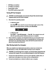
..., then click the arrow in the lower-right corner of the Start menu as an ExpressCard. 2. Do not use only the battery designed for other Dell computers. 1. After Working Inside Your Computer After you complete any telephone or network cables to turn them off your computer. 1. ...attached devices are turned off after the operating system shutdown process is complete. 2. CAUTION: To avoid damage to the computer, use batteries designed for this particular Dell computer. Shut down your operating system, press and hold the power button for about 4 seconds to your computer. 11 •...
..., then click the arrow in the lower-right corner of the Start menu as an ExpressCard. 2. Do not use only the battery designed for other Dell computers. 1. After Working Inside Your Computer After you complete any telephone or network cables to turn them off your computer. 1. ...attached devices are turned off after the operating system shutdown process is complete. 2. CAUTION: To avoid damage to the computer, use batteries designed for this particular Dell computer. Shut down your operating system, press and hold the power button for about 4 seconds to your computer. 11 •...

Owners Manual
Page 12
Connect your computer. 12 CAUTION: To connect a network cable, first plug the cable into the network device and then plug it into the computer. 3. Turn on your computer and all attached devices to their electrical outlets. 5. Replace the battery. 4.
Connect your computer. 12 CAUTION: To connect a network cable, first plug the cable into the network device and then plug it into the computer. 3. Turn on your computer and all attached devices to their electrical outlets. 5. Replace the battery. 4.
Owners Manual
Page 17
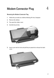
Insert a pin into the hole and pull the pin upwards to release the latch cover. 17 Pop open the rubber cover. 4. Remove the battery. 3. Modem Connector Plug 4 Removing the Modem Connector Plug 1. Identify the pin hole. 5. Follow the procedures in Before Working On Your Computer. 2.
Insert a pin into the hole and pull the pin upwards to release the latch cover. 17 Pop open the rubber cover. 4. Remove the battery. 3. Modem Connector Plug 4 Removing the Modem Connector Plug 1. Identify the pin hole. 5. Follow the procedures in Before Working On Your Computer. 2.

Owners Manual
Page 18
Identify the pin hole and insert a pin into the hole and pull the pin to lock the cover. 3. Place the modem cover. 2. Lock the rubber cover. 4. Installing the Modem Connector Plug 1. Install the Battery. 5. Follow the procedures in After Working Inside Your Computer. 18 6. Remove the cover.
Identify the pin hole and insert a pin into the hole and pull the pin to lock the cover. 3. Place the modem cover. 2. Lock the rubber cover. 4. Installing the Modem Connector Plug 1. Install the Battery. 5. Follow the procedures in After Working Inside Your Computer. 18 6. Remove the cover.

Owners Manual
Page 21
Follow the procedures in Before Working On Your Computer. 2. Slide the battery latches toward the unlock position. 3. Slide the battery out of the computer and remove it. 21 Battery 6 Removing the Battery 1.
Follow the procedures in Before Working On Your Computer. 2. Slide the battery latches toward the unlock position. 3. Slide the battery out of the computer and remove it. 21 Battery 6 Removing the Battery 1.

Owners Manual
Page 22
Slide the battery into its slot until it clicks into place. 2. Follow the procedures in After working inside your computer. 22 Installing the Battery 1.
Slide the battery into its slot until it clicks into place. 2. Follow the procedures in After working inside your computer. 22 Installing the Battery 1.

Owners Manual
Page 23
Remove the Battery. 3. Subscriber Identity Module (SIM) Card 7 Removing the Subscriber Identity Module (SIM) Card 1. Remove the SIM card from the system. 23 Follow the procedures in Before Working On Your Computer. 2. Insert the SIM card into the slot. 4.
Remove the Battery. 3. Subscriber Identity Module (SIM) Card 7 Removing the Subscriber Identity Module (SIM) Card 1. Remove the SIM card from the system. 23 Follow the procedures in Before Working On Your Computer. 2. Insert the SIM card into the slot. 4.

Owners Manual
Page 24
Installing the Subscriber Identity Module (SIM) Card 1. Install the Battery. 3. Slide the SIM card into its slot. 2. Follow the procedures in After Working Inside Your Computer. 24
Installing the Subscriber Identity Module (SIM) Card 1. Install the Battery. 3. Slide the SIM card into its slot. 2. Follow the procedures in After Working Inside Your Computer. 24
Owners Manual
Page 27
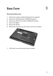
Follow the procedures in Before Working On Your Computer. 2. Remove the screws that secure the base cover to the computer. 7. Remove the Battery. 5. Lift the base cover up and away from the computer. 27 Remove the SD Card. 6. Base Cover 9 Removing the Base Cover 1. Remove the ATG Handle (only for E6420 ATG systems). 4. Remove the ATG Port Cover (only for E6420 ATG systems). 3.
Follow the procedures in Before Working On Your Computer. 2. Remove the screws that secure the base cover to the computer. 7. Remove the Battery. 5. Lift the base cover up and away from the computer. 27 Remove the SD Card. 6. Base Cover 9 Removing the Base Cover 1. Remove the ATG Handle (only for E6420 ATG systems). 4. Remove the ATG Port Cover (only for E6420 ATG systems). 3.

Owners Manual
Page 28
Install the ATG Handle (only for E6420 ATG systems). 6. Installing the Base Cover 1. Install the Battery. 5. Follow the procedures in After Working Inside Your Computer. 28 Tighten the screws that secure the base cover to align the screw holes correctly with the computer. 2. Install the ATG Port Cover (only for E6420 ATG systems). 7. Place the base cover to the computer. 3. Install the Secure Digital (SD) Card. 4.
Install the ATG Handle (only for E6420 ATG systems). 6. Installing the Base Cover 1. Install the Battery. 5. Follow the procedures in After Working Inside Your Computer. 28 Tighten the screws that secure the base cover to align the screw holes correctly with the computer. 2. Install the ATG Port Cover (only for E6420 ATG systems). 7. Place the base cover to the computer. 3. Install the Secure Digital (SD) Card. 4.
Owners Manual
Page 29
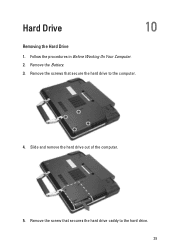
Slide and remove the hard drive out of the computer. 5. Remove the screw that secure the hard drive to the hard drive. 29 Remove the screws that secures the hard drive caddy to the computer. 4. Remove the Battery. 3. Follow the procedures in Before Working On Your Computer. 2. Hard Drive 10 Removing the Hard Drive 1.
Slide and remove the hard drive out of the computer. 5. Remove the screw that secure the hard drive to the hard drive. 29 Remove the screws that secures the hard drive caddy to the computer. 4. Remove the Battery. 3. Follow the procedures in Before Working On Your Computer. 2. Hard Drive 10 Removing the Hard Drive 1.


