Owner's Manual (PDF)
Page 18
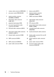
... (WEBCAM) 2 battery socket (BAT1) 3 processor socket (PROCESSOR) 4 memory-module connector (CHANNEL A DIMM 1) 5 memory-module connector (CHANNEL A DIMM 0) 6 CMOS reset jumper (SW50) 7 left speaker cable connector (LINE_OUT) 8 right speaker cable connector (LINE_OUT) 9 password reset jumper (E49) 10 SPI connector (E16) 11 processor heat-sink fan cable connector (CPU FAN) 12 power-button board...
... (WEBCAM) 2 battery socket (BAT1) 3 processor socket (PROCESSOR) 4 memory-module connector (CHANNEL A DIMM 1) 5 memory-module connector (CHANNEL A DIMM 0) 6 CMOS reset jumper (SW50) 7 left speaker cable connector (LINE_OUT) 8 right speaker cable connector (LINE_OUT) 9 password reset jumper (E49) 10 SPI connector (E16) 11 processor heat-sink fan cable connector (CPU FAN) 12 power-button board...
Owner's Manual (PDF)
Page 109
... if installed incorrectly. For additional safety best practices information, see the Regulatory Compliance Homepage at dell.com/regulatory_compliance. See "Removing the Back Cover" on page 49. Removing the Coin-Cell Battery CAUTION: Removing the coin-cell battery resets the BIOS settings to the manufacturer's instructions. See "Removing the System-Board Shield" on...
... if installed incorrectly. For additional safety best practices information, see the Regulatory Compliance Homepage at dell.com/regulatory_compliance. See "Removing the Back Cover" on page 49. Removing the Coin-Cell Battery CAUTION: Removing the coin-cell battery resets the BIOS settings to the manufacturer's instructions. See "Removing the System-Board Shield" on...
Owner's Manual (PDF)
Page 150
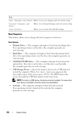
... message. 150 System Setup Insert the memory device into a USB port and restart the computer. Exit Save Changes and Reset Allows you to save changes and exit system setup Discard Changes and Reset Allows you to discard changes and exit system setup Load Default Allows you to restore the default settings Boot...
... message. 150 System Setup Insert the memory device into a USB port and restart the computer. Exit Save Changes and Reset Allows you to save changes and exit system setup Discard Changes and Reset Allows you to discard changes and exit system setup Load Default Allows you to restore the default settings Boot...
Owner's Manual (PDF)
Page 152
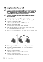
... from pins 1 and 2 and replace it on the system board. See "Removing the System-Board Shield" on page 49. 5 Locate the 3-pin password reset jumper (E49) on pins 2 and 3. 9 Replace the system-board shield. See "System Board Components" on page 17. 6 Remove the 2-pin jumper... Back Cover" on page 43. 4 Remove the system-board shield. For additional safety best practices information, see the Regulatory Compliance Homepage at dell.com/regulatory_compliance. See "Replacing the VESA-Mount Bracket" on page 11. Clearing Forgotten Passwords WARNING: Before working inside your computer, read the...
... from pins 1 and 2 and replace it on the system board. See "Removing the System-Board Shield" on page 49. 5 Locate the 3-pin password reset jumper (E49) on pins 2 and 3. 9 Replace the system-board shield. See "System Board Components" on page 17. 6 Remove the 2-pin jumper... Back Cover" on page 43. 4 Remove the system-board shield. For additional safety best practices information, see the Regulatory Compliance Homepage at dell.com/regulatory_compliance. See "Replacing the VESA-Mount Bracket" on page 11. Clearing Forgotten Passwords WARNING: Before working inside your computer, read the...
Owner's Manual (PDF)
Page 154
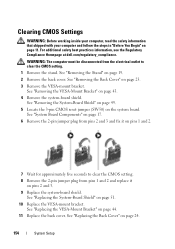
...VESA-mount bracket. See "Removing the Back Cover" on page 11. See "Removing the System-Board Shield" on page 49. 5 Locate the 3-pin CMOS reset jumper (SW50) on page 19. 2 Remove the back cover. See "System Board Components" on page 17. 6 Remove the 2-pin jumper plug from ...System-Board Shield" on page 43. 4 Remove the system-board shield. For additional safety best practices information, see the Regulatory Compliance Homepage at dell.com/regulatory_compliance. See "Replacing the VESA-Mount Bracket" on page 24. 154 System Setup WARNING: The computer must be disconnected from pins 1 ...
...VESA-mount bracket. See "Removing the Back Cover" on page 11. See "Removing the System-Board Shield" on page 49. 5 Locate the 3-pin CMOS reset jumper (SW50) on page 19. 2 Remove the back cover. See "System Board Components" on page 17. 6 Remove the 2-pin jumper plug from ...System-Board Shield" on page 43. 4 Remove the system-board shield. For additional safety best practices information, see the Regulatory Compliance Homepage at dell.com/regulatory_compliance. See "Replacing the VESA-Mount Bracket" on page 24. 154 System Setup WARNING: The computer must be disconnected from pins 1 ...


