Owner's Manual (PDF)
Page 1
Dell Inspiron One 2330 Owner's Manual Computer model: Inspiron One 2330 Regulatory model: W05C Regulatory type: W05C001
Dell Inspiron One 2330 Owner's Manual Computer model: Inspiron One 2330 Regulatory model: W05C Regulatory type: W05C001

Owner's Manual (PDF)
Page 2
... information that helps you make better use of Intel Corporation in the U.S. Information in this document is a registered trademark owned by Dell under license; A00 WARNING: A WARNING indicates a potential for property damage, personal injury, or death. is used in this document... to refer to either trademarks or registered trademarks of data if instructions are trademarks of Dell Inc. Trademarks used in this text: Dell™, the DELL logo, and Inspiron™ are not followed. and is strictly forbidden. CAUTION: A CAUTION indicates potential damage ...
... information that helps you make better use of Intel Corporation in the U.S. Information in this document is a registered trademark owned by Dell under license; A00 WARNING: A WARNING indicates a potential for property damage, personal injury, or death. is used in this document... to refer to either trademarks or registered trademarks of data if instructions are trademarks of Dell Inc. Trademarks used in this text: Dell™, the DELL logo, and Inspiron™ are not followed. and is strictly forbidden. CAUTION: A CAUTION indicates potential damage ...
Owner's Manual (PDF)
Page 3
Contents 1 Before You Begin 11 Turn Off Your Computer and Connected Devices . . . . 11 Safety Instructions 12 Recommended Tools 12 2 After Working Inside Your Computer . . . . 13 3 Technical Overview 15 Inside View of Your Computer 16 System Board Components 17 4 Stand 19 Removing the Stand 19 Replacing the Stand 21 5 Back Cover 23 Removing the Back Cover 23 Replacing the Back Cover 24 Contents 3
Contents 1 Before You Begin 11 Turn Off Your Computer and Connected Devices . . . . 11 Safety Instructions 12 Recommended Tools 12 2 After Working Inside Your Computer . . . . 13 3 Technical Overview 15 Inside View of Your Computer 16 System Board Components 17 4 Stand 19 Removing the Stand 19 Replacing the Stand 21 5 Back Cover 23 Removing the Back Cover 23 Replacing the Back Cover 24 Contents 3
Owner's Manual (PDF)
Page 4
6 B-CAS Card 25 Removing the B-CAS Card 25 Replacing the B-CAS card 27 7 Converter Board 29 Removing the Converter Board 29 Replacing the Converter Board 31 8 Power-Button Board 33 Removing the Power-Button Board 33 Replacing the Power-Button Board 34 9 Memory Module(s 35 Removing the Memory Module(s 35 Replacing the Memory Module(s 37 10 Optical Drive 39 Removing the Optical Drive 39 Replacing the Optical Drive 42 4 Contents
6 B-CAS Card 25 Removing the B-CAS Card 25 Replacing the B-CAS card 27 7 Converter Board 29 Removing the Converter Board 29 Replacing the Converter Board 31 8 Power-Button Board 33 Removing the Power-Button Board 33 Replacing the Power-Button Board 34 9 Memory Module(s 35 Removing the Memory Module(s 35 Replacing the Memory Module(s 37 10 Optical Drive 39 Removing the Optical Drive 39 Replacing the Optical Drive 42 4 Contents
Owner's Manual (PDF)
Page 5
11 VESA-Mount Bracket 43 Removing the VESA-Mount Bracket 43 Replacing the VESA-Mount Bracket 44 12 Hard Drive 45 Removing the Hard Drive 45 Replacing the Hard Drive 48 13 System-Board Shield 49 Removing the System-Board Shield 49 Replacing the System-Board Shield 51 14 TV Tuner Card 53 Removing the TV Tuner Card 53 Replacing the TV Tuner Card 56 15 Wireless Mini-Card 57 Removing the Wireless Mini-Card 57 Replacing the Wireless Mini-Card 59 Contents 5
11 VESA-Mount Bracket 43 Removing the VESA-Mount Bracket 43 Replacing the VESA-Mount Bracket 44 12 Hard Drive 45 Removing the Hard Drive 45 Replacing the Hard Drive 48 13 System-Board Shield 49 Removing the System-Board Shield 49 Replacing the System-Board Shield 51 14 TV Tuner Card 53 Removing the TV Tuner Card 53 Replacing the TV Tuner Card 56 15 Wireless Mini-Card 57 Removing the Wireless Mini-Card 57 Replacing the Wireless Mini-Card 59 Contents 5
Owner's Manual (PDF)
Page 6
16 Speakers 61 Removing the Speakers 61 Replacing the Speakers 63 17 Processor Heat-Sink 65 Removing the Processor Heat-Sink 65 Replacing the Processor Heat-Sink 67 18 Processor Heat-Sink Fan 69 Removing the Processor Heat-Sink Fan 69 Replacing the Processor Heat-Sink Fan 71 19 Processor 73 Removing the Processor 73 Replacing the Processor 75 20 Power-Supply Fan Bracket 77 Removing the Power-Supply Fan Bracket 77 Replacing the Power-Supply Fan Bracket 79 6 Contents
16 Speakers 61 Removing the Speakers 61 Replacing the Speakers 63 17 Processor Heat-Sink 65 Removing the Processor Heat-Sink 65 Replacing the Processor Heat-Sink 67 18 Processor Heat-Sink Fan 69 Removing the Processor Heat-Sink Fan 69 Replacing the Processor Heat-Sink Fan 71 19 Processor 73 Removing the Processor 73 Replacing the Processor 75 20 Power-Supply Fan Bracket 77 Removing the Power-Supply Fan Bracket 77 Replacing the Power-Supply Fan Bracket 79 6 Contents
Owner's Manual (PDF)
Page 7
21 I/O Cover 81 Removing the I/O Cover 81 Replacing the I/O Cover 83 22 I/O Board Shield 85 Removing the I/O Board Shield 85 Replacing the I/O Board Shield 88 23 Power-Supply Unit 89 Removing the Power-Supply Unit 89 Replacing the Power-Supply Unit 91 24 Power-Supply Fan 93 Removing the Power-Supply Fan 93 Replacing the Power-Supply Fan 95 25 TV-In Port 97 Removing the TV-In Port 97 Replacing the TV-In Port 99 Contents 7
21 I/O Cover 81 Removing the I/O Cover 81 Replacing the I/O Cover 83 22 I/O Board Shield 85 Removing the I/O Board Shield 85 Replacing the I/O Board Shield 88 23 Power-Supply Unit 89 Removing the Power-Supply Unit 89 Replacing the Power-Supply Unit 91 24 Power-Supply Fan 93 Removing the Power-Supply Fan 93 Replacing the Power-Supply Fan 95 25 TV-In Port 97 Removing the TV-In Port 97 Replacing the TV-In Port 99 Contents 7
Owner's Manual (PDF)
Page 8
26 Infrared Port 101 Removing the Infrared Port 101 Replacing the Infrared Port 103 27 I/O Board 105 Removing the I/O Board 105 Replacing the I/O Board 108 28 Coin-Cell Battery 109 Removing the Coin-Cell Battery 109 Replacing the Coin-Cell Battery 111 29 System Board 113 Removing the System Board 113 Replacing the System Board 115 Entering the Service Tag in the BIOS 116 30 Antenna Module(s 117 Removing the Antenna Module(s 117 Replacing the Antenna Module(s 120 8 Contents
26 Infrared Port 101 Removing the Infrared Port 101 Replacing the Infrared Port 103 27 I/O Board 105 Removing the I/O Board 105 Replacing the I/O Board 108 28 Coin-Cell Battery 109 Removing the Coin-Cell Battery 109 Replacing the Coin-Cell Battery 111 29 System Board 113 Removing the System Board 113 Replacing the System Board 115 Entering the Service Tag in the BIOS 116 30 Antenna Module(s 117 Removing the Antenna Module(s 117 Replacing the Antenna Module(s 120 8 Contents
Owner's Manual (PDF)
Page 9
31 Display Panel 123 Removing the Display Panel 123 Replacing the Display Panel 128 32 Infrared Sensor 131 Removing the Infrared Sensor 131 Replacing the Infrared Sensor 134 33 Camera Module 137 Removing the Camera Module 137 Replacing the Camera Module 140 34 System Setup 143 Overview 143 Entering System Setup 143 Clearing Forgotten Passwords 152 Clearing CMOS Settings 154 35 Flashing the BIOS 157 Contents 9
31 Display Panel 123 Removing the Display Panel 123 Replacing the Display Panel 128 32 Infrared Sensor 131 Removing the Infrared Sensor 131 Replacing the Infrared Sensor 134 33 Camera Module 137 Removing the Camera Module 137 Replacing the Camera Module 140 34 System Setup 143 Overview 143 Entering System Setup 143 Clearing Forgotten Passwords 152 Clearing CMOS Settings 154 35 Flashing the BIOS 157 Contents 9
Owner's Manual (PDF)
Page 11
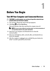
Before You Begin 11 Microsoft Windows shuts down instructions. 3 Disconnect your computer and all attached devices from the electrical outlets. 4 Disconnect all telephone cables, network cables, and attached devices from your computer. 1 Save and close all open files and exit all open programs. 2 Click Start and click Shut Down. Before You Begin Turn Off Your Computer and Connected Devices CAUTION: To avoid losing data, save and close all open files and exit all open programs before you are using a different operating system, see the documentation of your operating system for shut-...
Before You Begin 11 Microsoft Windows shuts down instructions. 3 Disconnect your computer and all attached devices from the electrical outlets. 4 Disconnect all telephone cables, network cables, and attached devices from your computer. 1 Save and close all open files and exit all open programs. 2 Click Start and click Shut Down. Before You Begin Turn Off Your Computer and Connected Devices CAUTION: To avoid losing data, save and close all open files and exit all open programs before you are using a different operating system, see the documentation of your operating system for shut-...
Owner's Manual (PDF)
Page 12
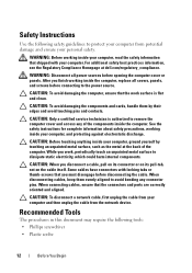
... computer, replace all power sources before disconnecting the cable. When disconnecting cables, keep them by touching an unpainted metal surface, such as the metal at dell.com/regulatory_compliance. CAUTION: To avoid damaging the components and cards, handle them evenly aligned to protect your computer from your computer, and protecting against electrostatic...
... computer, replace all power sources before disconnecting the cable. When disconnecting cables, keep them by touching an unpainted metal surface, such as the metal at dell.com/regulatory_compliance. CAUTION: To avoid damaging the components and cards, handle them evenly aligned to protect your computer from your computer, and protecting against electrostatic...
Owner's Manual (PDF)
Page 13
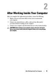
Failure to the electrical outlets CAUTION: Before turning on your computer, replace all screws and ensure that no stray screws remain inside your computer • Connect any external devices, cables, cards, and any other part(s) you complete the replacement procedures, ensure the following: • Replace all attached devices to do so may damage your computer and all screws and ensure that no stray screws remain inside the computer. After Working Inside Your Computer 13 After Working Inside Your Computer After you removed before working on your computer • Connect your ...
Failure to the electrical outlets CAUTION: Before turning on your computer, replace all screws and ensure that no stray screws remain inside your computer • Connect any external devices, cables, cards, and any other part(s) you complete the replacement procedures, ensure the following: • Replace all attached devices to do so may damage your computer and all screws and ensure that no stray screws remain inside the computer. After Working Inside Your Computer 13 After Working Inside Your Computer After you removed before working on your computer • Connect your ...

Owner's Manual (PDF)
Page 15
Technical Overview WARNING: Before working inside your computer, read the safety information that shipped with your computer and follow the steps in "Before You Begin" on page 11. For additional safety best practices information, see the Regulatory Compliance Homepage at dell.com/regulatory_compliance. Technical Overview 15
Technical Overview WARNING: Before working inside your computer, read the safety information that shipped with your computer and follow the steps in "Before You Begin" on page 11. For additional safety best practices information, see the Regulatory Compliance Homepage at dell.com/regulatory_compliance. Technical Overview 15
Owner's Manual (PDF)
Page 16
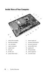
Inside View of Your Computer 4 3 2 1 5 6 7 8 16 15 1 optical-drive assembly 3 hard-drive assembly 5 coin-cell battery 7 memory module(s) 9 system board 11 I/O cover 13 B-CAS card 15 power-button board 11 12 13 14 9 10 2 power-supply unit 4 processor heat-sink fan 6 processor heat-sink 8 wireless Mini-Card 10 speakers (2) 12 I/O board shield 14 power-supply fan 16 converter board 16 Technical Overview
Inside View of Your Computer 4 3 2 1 5 6 7 8 16 15 1 optical-drive assembly 3 hard-drive assembly 5 coin-cell battery 7 memory module(s) 9 system board 11 I/O cover 13 B-CAS card 15 power-button board 11 12 13 14 9 10 2 power-supply unit 4 processor heat-sink fan 6 processor heat-sink 8 wireless Mini-Card 10 speakers (2) 12 I/O board shield 14 power-supply fan 16 converter board 16 Technical Overview
Owner's Manual (PDF)
Page 18
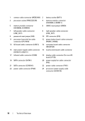
1 camera cable connector (WEBCAM) 2 battery socket (BAT1) 3 processor socket (PROCESSOR) 4 memory-module connector (CHANNEL A DIMM 1) 5 memory-module connector (CHANNEL A DIMM 0) 6 CMOS reset jumper (SW50) 7 left speaker cable connector (LINE_OUT) 8 right speaker cable connector (LINE_OUT) 9 password reset jumper (E49) 10 SPI connector (E16) 11 processor heat-sink fan cable connector (CPU FAN) 12 power-button board cable connector (FRONT_PANEL) 13 I/O board cable connector (LVDS1) 14 converter board cable connector (INVERTER) 15 main power-supply cable connector 16 touchscreen ...
1 camera cable connector (WEBCAM) 2 battery socket (BAT1) 3 processor socket (PROCESSOR) 4 memory-module connector (CHANNEL A DIMM 1) 5 memory-module connector (CHANNEL A DIMM 0) 6 CMOS reset jumper (SW50) 7 left speaker cable connector (LINE_OUT) 8 right speaker cable connector (LINE_OUT) 9 password reset jumper (E49) 10 SPI connector (E16) 11 processor heat-sink fan cable connector (CPU FAN) 12 power-button board cable connector (FRONT_PANEL) 13 I/O board cable connector (LVDS1) 14 converter board cable connector (INVERTER) 15 main power-supply cable connector 16 touchscreen ...
Owner's Manual (PDF)
Page 19
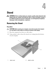
For additional safety best practices information, see the Regulatory Compliance Homepage at dell.com/regulatory_compliance. Removing the Stand Procedure CAUTION: Before opening your computer, ensure that shipped with your computer. 1 2 1 stand cover 2 plastic scribe Stand 19 Stand WARNING: ...
For additional safety best practices information, see the Regulatory Compliance Homepage at dell.com/regulatory_compliance. Removing the Stand Procedure CAUTION: Before opening your computer, ensure that shipped with your computer. 1 2 1 stand cover 2 plastic scribe Stand 19 Stand WARNING: ...
Owner's Manual (PDF)
Page 20
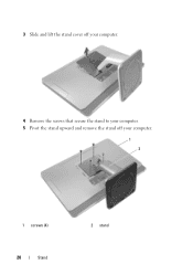
3 Slide and lift the stand cover off your computer. 4 Remove the screws that secure the stand to your computer. 5 Pivot the stand upward and remove the stand off your computer. 1 2 1 screws (4) 20 Stand 2 stand
3 Slide and lift the stand cover off your computer. 4 Remove the screws that secure the stand to your computer. 5 Pivot the stand upward and remove the stand off your computer. 1 2 1 screws (4) 20 Stand 2 stand
Owner's Manual (PDF)
Page 21
Replacing the Stand Procedure 1 Align the screw holes on the stand with the screw holes on your computer. 2 Replace the screws that secure the stand to your computer. 3 Slide the stand cover and snap it into place. 4 Follow the instructions in "After Working Inside Your Computer" on page 13. Stand 21
Replacing the Stand Procedure 1 Align the screw holes on the stand with the screw holes on your computer. 2 Replace the screws that secure the stand to your computer. 3 Slide the stand cover and snap it into place. 4 Follow the instructions in "After Working Inside Your Computer" on page 13. Stand 21

Owner's Manual (PDF)
Page 22
22 Stand
22 Stand
Owner's Manual (PDF)
Page 23
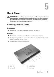
... shipped with your computer. 1 slots (2) 3 screws (4) 2 1 4 3 2 middle frame 4 back cover Back Cover 23 For additional safety best practices information, see the Regulatory Compliance Homepage at dell.com/regulatory_compliance. Back Cover WARNING: Before working inside your computer, read the safety information that secure the back cover to your computer. 2 Insert your finger...
... shipped with your computer. 1 slots (2) 3 screws (4) 2 1 4 3 2 middle frame 4 back cover Back Cover 23 For additional safety best practices information, see the Regulatory Compliance Homepage at dell.com/regulatory_compliance. Back Cover WARNING: Before working inside your computer, read the safety information that secure the back cover to your computer. 2 Insert your finger...
