Owner's Manual (PDF)
Page 9
31 Display Panel 123 Removing the Display Panel 123 Replacing the Display Panel 128 32 Infrared Sensor 131 Removing the Infrared Sensor 131 Replacing the Infrared Sensor 134 33 Camera Module 137 Removing the Camera Module 137 Replacing the Camera Module 140 34 System Setup 143 Overview 143 Entering System Setup 143 Clearing Forgotten Passwords 152 Clearing CMOS Settings 154 35 Flashing the BIOS 157 Contents 9
31 Display Panel 123 Removing the Display Panel 123 Replacing the Display Panel 128 32 Infrared Sensor 131 Removing the Infrared Sensor 131 Replacing the Infrared Sensor 134 33 Camera Module 137 Removing the Camera Module 137 Replacing the Camera Module 140 34 System Setup 143 Overview 143 Entering System Setup 143 Clearing Forgotten Passwords 152 Clearing CMOS Settings 154 35 Flashing the BIOS 157 Contents 9
Owner's Manual (PDF)
Page 18
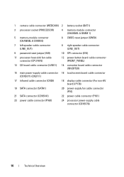
1 camera cable connector (WEBCAM) 2 battery socket (BAT1) 3 processor socket (PROCESSOR) 4 memory-module connector (CHANNEL A DIMM 1) 5 memory-module connector (CHANNEL A DIMM 0) 6 CMOS reset jumper (SW50) 7 left speaker ...
1 camera cable connector (WEBCAM) 2 battery socket (BAT1) 3 processor socket (PROCESSOR) 4 memory-module connector (CHANNEL A DIMM 1) 5 memory-module connector (CHANNEL A DIMM 0) 6 CMOS reset jumper (SW50) 7 left speaker ...
Owner's Manual (PDF)
Page 137
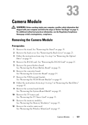
... 39. 4 Remove the B-CAS card. For additional safety best practices information, see the Regulatory Compliance Homepage at dell.com/regulatory_compliance. See "Removing the Converter Board" on page 53. 11 Remove the memory modules. Removing the Camera Module Prerequisites 1 Remove the stand. See "Removing the TV Tuner Card" on page 29. 7 Remove the...
... 39. 4 Remove the B-CAS card. For additional safety best practices information, see the Regulatory Compliance Homepage at dell.com/regulatory_compliance. See "Removing the Converter Board" on page 53. 11 Remove the memory modules. Removing the Camera Module Prerequisites 1 Remove the stand. See "Removing the TV Tuner Card" on page 29. 7 Remove the...
Owner's Manual (PDF)
Page 138
... Remove the I /O board shield. See "Removing the I /O cover. 13 Remove the power-supply fan bracket. See "Removing the Power-Supply Unit" on page 123. 138 Camera Module See "Removing the Display Panel" on page 89. 18 Remove the speakers. See "Removing the I/O Board Shield" on page 65. 21 Remove the processor...
... Remove the I /O board shield. See "Removing the I /O cover. 13 Remove the power-supply fan bracket. See "Removing the Power-Supply Unit" on page 123. 138 Camera Module See "Removing the Display Panel" on page 89. 18 Remove the speakers. See "Removing the I/O Board Shield" on page 65. 21 Remove the processor...
Owner's Manual (PDF)
Page 139
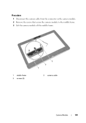
Procedure 1 Disconnect the camera cable from the connector on the camera module. 2 Remove the screws that secure the camera module to the middle frame. 3 Lift the camera module off the middle frame. 1 middle frame 3 screws (2) 3 2 1 2 camera cable Camera Module 139
Procedure 1 Disconnect the camera cable from the connector on the camera module. 2 Remove the screws that secure the camera module to the middle frame. 3 Lift the camera module off the middle frame. 1 middle frame 3 screws (2) 3 2 1 2 camera cable Camera Module 139
Owner's Manual (PDF)
Page 140
...the I /O Board Shield" on page 108. 6 Replace the speakers. See "Replacing the I /O cover. See "Replacing the B-CAS card" on page 56. 140 Camera Module See "Replacing the TV Tuner Card" on page 27. 11 Replace the power-supply fan bracket. See "Replacing the Memory Module(s)" on page 71... modules. See "Replacing the Display Panel" on page 128. 2 Follow the instructions from step 1 to the connector on the camera module. Replacing the Camera Module Procedure 1 Align the screw holes on the camera module with the screw holes on the middle frame. 2 Replace the screws that secure the...
...the I /O Board Shield" on page 108. 6 Replace the speakers. See "Replacing the I /O cover. See "Replacing the B-CAS card" on page 56. 140 Camera Module See "Replacing the TV Tuner Card" on page 27. 11 Replace the power-supply fan bracket. See "Replacing the Memory Module(s)" on page 71... modules. See "Replacing the Display Panel" on page 128. 2 Follow the instructions from step 1 to the connector on the camera module. Replacing the Camera Module Procedure 1 Align the screw holes on the camera module with the screw holes on the middle frame. 2 Replace the screws that secure the...
Owner's Manual (PDF)
Page 141
... 21. 24 Follow the instructions in "Replacing the Hard Drive" on page 13. See "Replacing the Converter Board" on page 34. 20 Replace B-CAS card. Camera Module 141 See "Replacing the Power-Button Board" on page 31. 19 Replace power-button board. See "Replacing the VESA-Mount Bracket" on page 24...
... 21. 24 Follow the instructions in "Replacing the Hard Drive" on page 13. See "Replacing the Converter Board" on page 34. 20 Replace B-CAS card. Camera Module 141 See "Replacing the Power-Button Board" on page 31. 19 Replace power-button board. See "Replacing the VESA-Mount Bracket" on page 24...


