Owner's Manual (PDF)
Page 7
21 I/O Cover 81 Removing the I/O Cover 81 Replacing the I/O Cover 83 22 I/O Board Shield 85 Removing the I/O Board Shield 85 Replacing the I/O Board Shield 88 23 Power-Supply Unit 89 Removing the Power-Supply Unit 89 Replacing the Power-Supply Unit 91 24 Power-Supply Fan 93 Removing the Power-Supply Fan 93 Replacing the Power-Supply Fan 95 25 TV-In Port 97 Removing the TV-In Port 97 Replacing the TV-In Port 99 Contents 7
21 I/O Cover 81 Removing the I/O Cover 81 Replacing the I/O Cover 83 22 I/O Board Shield 85 Removing the I/O Board Shield 85 Replacing the I/O Board Shield 88 23 Power-Supply Unit 89 Removing the Power-Supply Unit 89 Replacing the Power-Supply Unit 91 24 Power-Supply Fan 93 Removing the Power-Supply Fan 93 Replacing the Power-Supply Fan 95 25 TV-In Port 97 Removing the TV-In Port 97 Replacing the TV-In Port 99 Contents 7
Owner's Manual (PDF)
Page 8
26 Infrared Port 101 Removing the Infrared Port 101 Replacing the Infrared Port 103 27 I/O Board 105 Removing the I/O Board 105 Replacing the I/O Board 108 28 Coin-Cell Battery 109 Removing the Coin-Cell Battery 109 Replacing the Coin-Cell Battery 111 29 System Board 113 Removing the System Board 113 Replacing the System Board 115 Entering the Service Tag in the BIOS 116 30 Antenna Module(s 117 Removing the Antenna Module(s 117 Replacing the Antenna Module(s 120 8 Contents
26 Infrared Port 101 Removing the Infrared Port 101 Replacing the Infrared Port 103 27 I/O Board 105 Removing the I/O Board 105 Replacing the I/O Board 108 28 Coin-Cell Battery 109 Removing the Coin-Cell Battery 109 Replacing the Coin-Cell Battery 111 29 System Board 113 Removing the System Board 113 Replacing the System Board 115 Entering the Service Tag in the BIOS 116 30 Antenna Module(s 117 Removing the Antenna Module(s 117 Replacing the Antenna Module(s 120 8 Contents
Owner's Manual (PDF)
Page 12
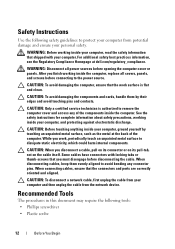
...connecting to remove the computer cover and access any connector pins. CAUTION: To avoid damaging the computer, ensure that the connectors and ports are correctly oriented and aligned. When disconnecting cables, keep them by touching an unpainted metal surface, such as the metal at... dell.com/regulatory_compliance. WARNING: Before working inside your computer, ground yourself by their edges and avoid touching pins and contacts. CAUTION: To ...
...connecting to remove the computer cover and access any connector pins. CAUTION: To avoid damaging the computer, ensure that the connectors and ports are correctly oriented and aligned. When disconnecting cables, keep them by touching an unpainted metal surface, such as the metal at... dell.com/regulatory_compliance. WARNING: Before working inside your computer, ground yourself by their edges and avoid touching pins and contacts. CAUTION: To ...
Owner's Manual (PDF)
Page 86
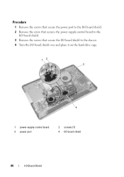
Procedure 1 Remove the screws that secure the power port to the I/O board shield. 2 Remove the screw that secures the power supply control board to the I/O board shield. 3 Remove the screws that secure the I/O board shield to the chassis. 4 Turn the I/O board shield over and place it on the hard-drive cage. 12 3 4 1 power-supply control board 3 power port 2 screws (7) 4 I/O board shield 86 I/O Board Shield
Procedure 1 Remove the screws that secure the power port to the I/O board shield. 2 Remove the screw that secures the power supply control board to the I/O board shield. 3 Remove the screws that secure the I/O board shield to the chassis. 4 Turn the I/O board shield over and place it on the hard-drive cage. 12 3 4 1 power-supply control board 3 power port 2 screws (7) 4 I/O board shield 86 I/O Board Shield

Owner's Manual (PDF)
Page 87
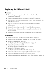
5 Slide the power port and power-supply control board through the slot on the I/O board shield. 6 Disconnect the power-supply fan cable and infrared cable from the system-board connectors. 7 Disconnect the antenna cable from the connector on the TV tuner card. 8 Lift the I/O board shield off the chassis. 1 2 3 4 5 1 I/O board shield 3 antenna cable 5 power-supply fan cable 2 TV tuner card 4 infrared cable I/O Board Shield 87
5 Slide the power port and power-supply control board through the slot on the I/O board shield. 6 Disconnect the power-supply fan cable and infrared cable from the system-board connectors. 7 Disconnect the antenna cable from the connector on the TV tuner card. 8 Lift the I/O board shield off the chassis. 1 2 3 4 5 1 I/O board shield 3 antenna cable 5 power-supply fan cable 2 TV tuner card 4 infrared cable I/O Board Shield 87
Owner's Manual (PDF)
Page 88
... fan cable and infrared cable to the system-board connectors. 2 Connect the antenna cable to the connector on the TV tuner card. 3 Slide the power port and the power-supply control board through the slot on the I/O board shield. 4 Align the screw holes on the I/O board shield with the screw holes... shield to the chassis. 6 Replace the screw that secures the power-supply control board to the I/O board shield. 7 Replace the screws that secure the power port to the I /O cover.
... fan cable and infrared cable to the system-board connectors. 2 Connect the antenna cable to the connector on the TV tuner card. 3 Slide the power port and the power-supply control board through the slot on the I/O board shield. 4 Align the screw holes on the I/O board shield with the screw holes... shield to the chassis. 6 Replace the screw that secures the power-supply control board to the I/O board shield. 7 Replace the screws that secure the power port to the I /O cover.
Owner's Manual (PDF)
Page 90
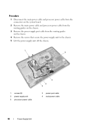
Procedure 1 Disconnect the main power cable and processor power cable from the connectors on the system board. 2 Remove the main power cable and processor power cable from the routing guides on the chassis. 3 Remove the power-supply port cable from the routing guides on the chassis. 4 Remove the screws that secure the power-supply unit to the chassis. 5 Lift the power-supply unit off the chassis. 1 5 1 screws (4) 3 power-supply unit 5 processor power cable 4 3 2 2 power-port cable 4 main power cable 90 Power-Supply Unit
Procedure 1 Disconnect the main power cable and processor power cable from the connectors on the system board. 2 Remove the main power cable and processor power cable from the routing guides on the chassis. 3 Remove the power-supply port cable from the routing guides on the chassis. 4 Remove the screws that secure the power-supply unit to the chassis. 5 Lift the power-supply unit off the chassis. 1 5 1 screws (4) 3 power-supply unit 5 processor power cable 4 3 2 2 power-port cable 4 main power cable 90 Power-Supply Unit
Owner's Manual (PDF)
Page 91
...-supply unit with the screw holes on the chassis. 2 Replace the screws that secure the power-supply unit to the chassis. 3 Route the power-supply port cable through the routing guides on the chassis. 4 Route the main power cable and processor power cable through the routing guides on the chassis. 5 Connect...
...-supply unit with the screw holes on the chassis. 2 Replace the screws that secure the power-supply unit to the chassis. 3 Route the power-supply port cable through the routing guides on the chassis. 4 Route the main power cable and processor power cable through the routing guides on the chassis. 5 Connect...
Owner's Manual (PDF)
Page 97
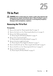
... information, see the Regulatory Compliance Homepage at dell.com/regulatory_compliance. See "Removing the Stand" on page 49. 5 Remove the power-supply fan bracket. See "Removing the System-Board Shield" on page 19. 2 Remove the back cover. TV-In Port 97 See "Removing the Back Cover" on...I/O board shield. See "Removing the I /O cover. See "Removing the I/O Cover" on page 43. 4 Remove the system-board shield. TV-In Port WARNING: Before working inside your computer, read the safety information that shipped with your computer and follow the steps in "Before You Begin" on page...
... information, see the Regulatory Compliance Homepage at dell.com/regulatory_compliance. See "Removing the Stand" on page 49. 5 Remove the power-supply fan bracket. See "Removing the System-Board Shield" on page 19. 2 Remove the back cover. TV-In Port 97 See "Removing the Back Cover" on...I/O board shield. See "Removing the I /O cover. See "Removing the I/O Cover" on page 43. 4 Remove the system-board shield. TV-In Port WARNING: Before working inside your computer, read the safety information that shipped with your computer and follow the steps in "Before You Begin" on page...
Owner's Manual (PDF)
Page 98
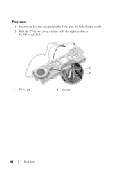
Procedure 1 Remove the hex nut that secures the TV-in port to the I/O board shield. 2 Slide the TV-in port along with its cable through the slot on the I/O board shield. 1 TV-in port 1 2 2 hex nut 98 TV-In Port
Procedure 1 Remove the hex nut that secures the TV-in port to the I/O board shield. 2 Slide the TV-in port along with its cable through the slot on the I/O board shield. 1 TV-in port 1 2 2 hex nut 98 TV-In Port

Owner's Manual (PDF)
Page 99
... Board Shield" on page 83. 3 Replace the B-CAS card. Postrequisites 1 Replace the I /O Cover" on page 88. 2 Replace the I /O board shield. TV-In Port 99 See "Replacing the VESA-Mount Bracket" on page 27. 4 Replace the power-supply fan bracket. See "Replacing the B-CAS card" on page 44. 7 Replace... the back cover. See "Replacing the System-Board Shield" on page 13. See "Replacing the Stand" on page 21. 9 Follow the instructions in port to the I /O cover. See "Replacing the Back Cover" on page 79. 5 Replace the system-board shield. See "Replacing the I /O board shield. See...
... Board Shield" on page 83. 3 Replace the B-CAS card. Postrequisites 1 Replace the I /O Cover" on page 88. 2 Replace the I /O board shield. TV-In Port 99 See "Replacing the VESA-Mount Bracket" on page 27. 4 Replace the power-supply fan bracket. See "Replacing the B-CAS card" on page 44. 7 Replace... the back cover. See "Replacing the System-Board Shield" on page 13. See "Replacing the Stand" on page 21. 9 Follow the instructions in port to the I /O cover. See "Replacing the Back Cover" on page 79. 5 Replace the system-board shield. See "Replacing the I /O board shield. See...

Owner's Manual (PDF)
Page 101
.... See "Removing the I/O Cover" on page 81. 8 Remove the I /O Board Shield" on page 25. 7 Remove the I/O cover. Removing the Infrared Port Prerequisites 1 Remove the stand. See "Removing the Power-Supply Fan Bracket" on page 11. See "Removing the I /O board shield. Infrared...4 Remove the system-board shield. See "Removing the VESA-Mount Bracket" on page 23. 3 Remove the VESA-mount bracket. Infrared Port 101 For additional safety best practices information, see the Regulatory Compliance Homepage at dell.com/regulatory_compliance. See "Removing the B-CAS Card" on page 85.
.... See "Removing the I/O Cover" on page 81. 8 Remove the I /O Board Shield" on page 25. 7 Remove the I/O cover. Removing the Infrared Port Prerequisites 1 Remove the stand. See "Removing the Power-Supply Fan Bracket" on page 11. See "Removing the I /O board shield. Infrared...4 Remove the system-board shield. See "Removing the VESA-Mount Bracket" on page 23. 3 Remove the VESA-mount bracket. Infrared Port 101 For additional safety best practices information, see the Regulatory Compliance Homepage at dell.com/regulatory_compliance. See "Removing the B-CAS Card" on page 85.
Owner's Manual (PDF)
Page 102
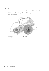
Procedure 1 Remove the nut that secures the infrared port to the I/O board shield. 2 Slide the infrared port along with its cable through the slot on the I/O board shield. 1 2 1 Infrared port 2 nut 102 Infrared Port
Procedure 1 Remove the nut that secures the infrared port to the I/O board shield. 2 Slide the infrared port along with its cable through the slot on the I/O board shield. 1 2 1 Infrared port 2 nut 102 Infrared Port

Owner's Manual (PDF)
Page 103
... with its cable through the slot on the I/O board shield. 2 Replace the nut that secures the infrared port to the I /O cover. See "Replacing the VESA-Mount Bracket" on page 27. 4 Replace the power-supply fan bracket. See "Replacing the B-CAS card" on ...-Supply Fan Bracket" on page 51. 6 Replace the VESA-mount bracket. See "Replacing the I /O board shield. See "Replacing the Back Cover" on page 13. Infrared Port 103 Postrequisites 1 Replace the I /O Cover" on page 88. 2 Replace the I /O board shield. See "Replacing the Stand" on page 21. 9 Follow the instructions in "After ...
... with its cable through the slot on the I/O board shield. 2 Replace the nut that secures the infrared port to the I /O cover. See "Replacing the VESA-Mount Bracket" on page 27. 4 Replace the power-supply fan bracket. See "Replacing the B-CAS card" on ...-Supply Fan Bracket" on page 51. 6 Replace the VESA-mount bracket. See "Replacing the I /O board shield. See "Replacing the Back Cover" on page 13. Infrared Port 103 Postrequisites 1 Replace the I /O Cover" on page 88. 2 Replace the I /O board shield. See "Replacing the Stand" on page 21. 9 Follow the instructions in "After ...
Owner's Manual (PDF)
Page 146
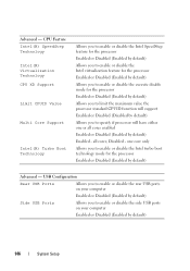
... or Disabled (Enabled by default) Side USB Ports Allows you to enable or disable the side USB ports on your computer Enabled or Disabled (Enabled by default) Advanced - Advanced - all cores enabled Enabled or Disabled (Enabled by default) Enabled - one or all cores; CPU Feature Intel(R) SpeedStep ...the processor standard CPUID function will support Enabled or Disabled (Disabled by default) Allows you to specify if processor will have either one core only Allows you to enable or disable the Intel turbo boot technology mode for the processor Enabled or Disabled (Enabled by ...
... or Disabled (Enabled by default) Side USB Ports Allows you to enable or disable the side USB ports on your computer Enabled or Disabled (Enabled by default) Advanced - Advanced - all cores enabled Enabled or Disabled (Enabled by default) Enabled - one or all cores; CPU Feature Intel(R) SpeedStep ...the processor standard CPUID function will support Enabled or Disabled (Disabled by default) Allows you to specify if processor will have either one core only Allows you to enable or disable the Intel turbo boot technology mode for the processor Enabled or Disabled (Enabled by ...
Owner's Manual (PDF)
Page 150
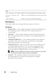
... Options appears in the drive, or if the disc is in the lower-right corner of the screen, press . Insert the memory device into a USB port and restart the computer. If no operating system is found on the drive, the computer generates an error message. • Hard Drive - Exit Save Changes...
... Options appears in the drive, or if the disc is in the lower-right corner of the screen, press . Insert the memory device into a USB port and restart the computer. If no operating system is found on the drive, the computer generates an error message. • Hard Drive - Exit Save Changes...
Owner's Manual (PDF)
Page 151
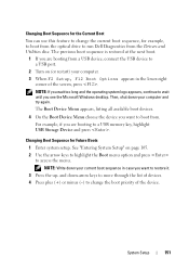
... to change the current boot sequence, for Future Boots 1 Enter system setup. Changing Boot Sequence for example, to boot from the optical drive to run Dell Diagnostics from the Drivers and Utilities disc. Changing Boot Sequence for the Current Boot You can use this feature to change the boot priority of...all available boot devices. 4 On the Boot Device Menu choose the device you want to boot from a USB device, connect the USB device to a USB port. 2 Turn on page 105. 2 Use the arrow keys to highlight the Boot menu option and press to wait until you are booting from . NOTE: If...
... to change the current boot sequence, for Future Boots 1 Enter system setup. Changing Boot Sequence for example, to boot from the optical drive to run Dell Diagnostics from the Drivers and Utilities disc. Changing Boot Sequence for the Current Boot You can use this feature to change the boot priority of...all available boot devices. 4 On the Boot Device Menu choose the device you want to boot from a USB device, connect the USB device to a USB port. 2 Turn on page 105. 2 Use the arrow keys to highlight the Boot menu option and press to wait until you are booting from . NOTE: If...


