Owners Manual
Page 1
P18F003 P18F002; Dell Inspiron M5040/15-N5040/ 15-N5050 Owner's Manual Regulatory model: P18F Regulatory type: P18F001;
P18F003 P18F002; Dell Inspiron M5040/15-N5040/ 15-N5050 Owner's Manual Regulatory model: P18F Regulatory type: P18F001;
Owners Manual
Page 2
... Dell™, the DELL logo, and Inspiron™ are not followed. P18F002; WARNING: A WARNING indicates a potential for property damage, personal injury, or death. is a registered trademark owned by Bluetooth SIG, Inc.; Notes, Cautions, and Warnings NOTE: A NOTE indicates important information that helps you make better use of Dell Inc... of data if instructions are trademarks of Microsoft Corporation in any manner whatsoever without notice. © 2011 Dell Inc. A00 Microsoft®, Windows®, and the Windows start button logo are either trademarks or registered trademarks of...
... Dell™, the DELL logo, and Inspiron™ are not followed. P18F002; WARNING: A WARNING indicates a potential for property damage, personal injury, or death. is a registered trademark owned by Bluetooth SIG, Inc.; Notes, Cautions, and Warnings NOTE: A NOTE indicates important information that helps you make better use of Dell Inc... of data if instructions are trademarks of Microsoft Corporation in any manner whatsoever without notice. © 2011 Dell Inc. A00 Microsoft®, Windows®, and the Windows start button logo are either trademarks or registered trademarks of...
Owners Manual
Page 3
Contents 1 Before You Begin 9 Recommended Tools 9 Turning Off Your Computer 9 Before Working Inside Your Computer 10 2 Battery 13 Removing the Battery 13 Replacing the Battery 14 3 Keyboard 15 Removing the Keyboard 15 Replacing the Keyboard 17 4 Memory Module(s 19 Removing the Memory Module(s 19 Replacing the Memory Module(s 20 5 Optical Drive 23 Removing the Optical Drive 23 Contents 3
Contents 1 Before You Begin 9 Recommended Tools 9 Turning Off Your Computer 9 Before Working Inside Your Computer 10 2 Battery 13 Removing the Battery 13 Replacing the Battery 14 3 Keyboard 15 Removing the Keyboard 15 Replacing the Keyboard 17 4 Memory Module(s 19 Removing the Memory Module(s 19 Replacing the Memory Module(s 20 5 Optical Drive 23 Removing the Optical Drive 23 Contents 3
Owners Manual
Page 4
Replacing the Optical Drive 24 6 Wireless Mini-Card 25 Removing the Mini-Card 25 Replacing the Mini-Card 27 7 Palm-Rest Assembly 29 Removing the Palm-Rest Assembly 29 Replacing the Palm-Rest Assembly 32 8 Power Button Board 35 Removing the Power Button Board 35 Replacing the Power Button Board 36 9 Hard Drive 37 Removing the Hard Drive 37 Replacing the Hard Drive 39 10 Coin-Cell Battery 41 Removing the Coin-Cell Battery 41 Replacing the Coin-Cell Battery 42 4 Contents
Replacing the Optical Drive 24 6 Wireless Mini-Card 25 Removing the Mini-Card 25 Replacing the Mini-Card 27 7 Palm-Rest Assembly 29 Removing the Palm-Rest Assembly 29 Replacing the Palm-Rest Assembly 32 8 Power Button Board 35 Removing the Power Button Board 35 Replacing the Power Button Board 36 9 Hard Drive 37 Removing the Hard Drive 37 Replacing the Hard Drive 39 10 Coin-Cell Battery 41 Removing the Coin-Cell Battery 41 Replacing the Coin-Cell Battery 42 4 Contents
Owners Manual
Page 5
11 USB Board 43 Removing the USB Board 43 Replacing the USB Board 44 12 Thermal Cooling Assembly 45 Removing the Thermal Cooling Assembly 45 Replacing the Thermal Cooling Assembly 46 13 Processor Module (For Inspiron 15-N5050/15-N5040 Only 47 Removing the Processor Module 47 Replacing the Processor Module 48 14 Hinge Cover 51 Removing the Hinge Cover 51 Replacing the Hinge Cover 53 15 Display 55 Display Assembly 55 Removing the Display Assembly 55 Replacing the Display Assembly 58 Display Bezel 59 Removing the Display Bezel 59 Replacing the Display Bezel 60 Contents 5
11 USB Board 43 Removing the USB Board 43 Replacing the USB Board 44 12 Thermal Cooling Assembly 45 Removing the Thermal Cooling Assembly 45 Replacing the Thermal Cooling Assembly 46 13 Processor Module (For Inspiron 15-N5050/15-N5040 Only 47 Removing the Processor Module 47 Replacing the Processor Module 48 14 Hinge Cover 51 Removing the Hinge Cover 51 Replacing the Hinge Cover 53 15 Display 55 Display Assembly 55 Removing the Display Assembly 55 Replacing the Display Assembly 58 Display Bezel 59 Removing the Display Bezel 59 Replacing the Display Bezel 60 Contents 5
Owners Manual
Page 6
Removing the Display Panel 60 Replacing the Display Panel 63 16 Camera Module 65 Removing the Camera Module 65 Replacing the Camera Module 66 17 System Board 67 Removing the System Board 67 Replacing the System Board 69 Entering the Service Tag in the BIOS 70 18 Flashing the BIOS 71 6 Contents
Removing the Display Panel 60 Replacing the Display Panel 63 16 Camera Module 65 Removing the Camera Module 65 Replacing the Camera Module 66 17 System Board 67 Removing the System Board 67 Replacing the System Board 69 Entering the Service Tag in the BIOS 70 18 Flashing the BIOS 71 6 Contents
Owners Manual
Page 9
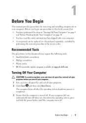
... document may require the following tools: • Small flat-blade screwdriver • Phillips screwdriver • Plastic scribe • BIOS executable update program available at support.dell.com Turning Off Your Computer CAUTION: To avoid losing data, save and close all open files and exit all open programs. 2 Click Start and then...
... document may require the following tools: • Small flat-blade screwdriver • Phillips screwdriver • Plastic scribe • BIOS executable update program available at support.dell.com Turning Off Your Computer CAUTION: To avoid losing data, save and close all open files and exit all open programs. 2 Click Start and then...
Owners Manual
Page 10
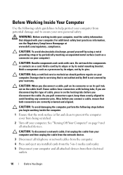
...safety guidelines to servicing that shipped with your computer. For additional safety best practices information, see the Regulatory Compliance Homepage at www.dell.com/regulatory_compliance. Before Working Inside Your Computer Use the following steps before you disconnect the cable. CAUTION: Only a certified service ... to avoid bending any installed cards from the 3-in on your computer, read the safety information that is not authorized by Dell is flat and clean to prevent the computer cover from being scratched. 2 Turn off your computer. if you pull connectors apart...
...safety guidelines to servicing that shipped with your computer. For additional safety best practices information, see the Regulatory Compliance Homepage at www.dell.com/regulatory_compliance. Before Working Inside Your Computer Use the following steps before you disconnect the cable. CAUTION: Only a certified service ... to avoid bending any installed cards from the 3-in on your computer, read the safety information that is not authorized by Dell is flat and clean to prevent the computer cover from being scratched. 2 Turn off your computer. if you pull connectors apart...
Owners Manual
Page 11
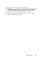
CAUTION: To help prevent damage to the system board, remove the main battery, see "Removing the Battery" on page 13. 8 Turn the computer top-side up, open the display, and press the power button to ground the system board. See "Removing the Battery" on page 13, before working inside the computer. 7 Remove the battery. 6 Disconnect all attached devices from your computer. Before You Begin 11
CAUTION: To help prevent damage to the system board, remove the main battery, see "Removing the Battery" on page 13. 8 Turn the computer top-side up, open the display, and press the power button to ground the system board. See "Removing the Battery" on page 13, before working inside the computer. 7 Remove the battery. 6 Disconnect all attached devices from your computer. Before You Begin 11

Owners Manual
Page 12
12 Before You Begin
12 Before You Begin
Owners Manual
Page 13
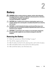
..., ground yourself by using a wrist grounding strap or by your computer). CAUTION: To avoid damage to the computer, use batteries designed for this particular Dell computer. Removing the Battery 1 Follow the instructions in "Before You Begin" on page 9. 2 Turn off the computer and turn it over. 3...battery out of the battery bay. 2 Battery WARNING: Before working inside your computer, read the safety information that is not authorized by Dell is not covered by periodically touching an unpainted metal surface (such as a connector on your computer. Do not use only the battery designed...
..., ground yourself by using a wrist grounding strap or by your computer). CAUTION: To avoid damage to the computer, use batteries designed for this particular Dell computer. Removing the Battery 1 Follow the instructions in "Before You Begin" on page 9. 2 Turn off the computer and turn it over. 3...battery out of the battery bay. 2 Battery WARNING: Before working inside your computer, read the safety information that is not authorized by Dell is not covered by periodically touching an unpainted metal surface (such as a connector on your computer. Do not use only the battery designed...
Owners Manual
Page 14
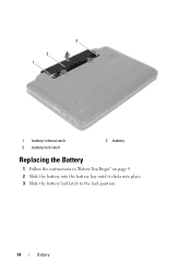
3 2 1 1 battery release latch 3 battery lock latch 2 battery Replacing the Battery 1 Follow the instructions in "Before You Begin" on page 9. 2 Slide the battery into the battery bay until it clicks into place. 3 Slide the battery lock latch to the lock position. 14 Battery
3 2 1 1 battery release latch 3 battery lock latch 2 battery Replacing the Battery 1 Follow the instructions in "Before You Begin" on page 9. 2 Slide the battery into the battery bay until it clicks into place. 3 Slide the battery lock latch to the lock position. 14 Battery
Owners Manual
Page 15
... touching an unpainted metal surface (such as possible. 4 Using a plastic scribe, release the four tabs that is not authorized by Dell is not covered by your warranty. CAUTION: The keycaps on your computer). CAUTION: Only a certified service technician should perform repairs on... are fragile, easily dislodged, and time-consuming to the system board, remove the main battery, see the Regulatory Compliance Homepage at www.dell.com/regulatory_compliance. For additional safety best practices information, see "Removing the Battery" on page 9. 2 Remove the battery. CAUTION: To ...
... touching an unpainted metal surface (such as possible. 4 Using a plastic scribe, release the four tabs that is not authorized by Dell is not covered by your warranty. CAUTION: The keycaps on your computer). CAUTION: Only a certified service technician should perform repairs on... are fragile, easily dislodged, and time-consuming to the system board, remove the main battery, see the Regulatory Compliance Homepage at www.dell.com/regulatory_compliance. For additional safety best practices information, see "Removing the Battery" on page 9. 2 Remove the battery. CAUTION: To ...
Owners Manual
Page 16
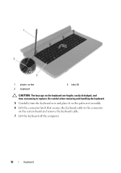
1 2 3 1 plastic scribe 3 keyboard 2 tabs (4) CAUTION: The keycaps on the system board and remove the keyboard cable. 7 Lift the keyboard off the computer. 16 Keyboard Be careful when removing and handling the keyboard. 5 Carefully turn the keyboard over and place it on the palm rest assembly. 6 Lift the connector latch that secures the keyboard cable to the connector on the keyboard are fragile, easily dislodged, and time-consuming to replace.
1 2 3 1 plastic scribe 3 keyboard 2 tabs (4) CAUTION: The keycaps on the system board and remove the keyboard cable. 7 Lift the keyboard off the computer. 16 Keyboard Be careful when removing and handling the keyboard. 5 Carefully turn the keyboard over and place it on the palm rest assembly. 6 Lift the connector latch that secures the keyboard cable to the connector on the keyboard are fragile, easily dislodged, and time-consuming to replace.
Owners Manual
Page 17
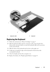
Press down on the connector latch to secure the keyboard cable to lock the four tabs securing the keyboard. 5 Close the display and turn the computer over. 6 Replace the battery. Keyboard 17 See "Replacing the Battery" on page 14. 1 2 1 keyboard cable 2 keyboard Replacing the Keyboard 1 Follow the instructions in "Before You Begin" on page 9. 2 Slide the keyboard cable into the slots on the palm rest. 4 Gently press around the edges of the keyboard to the connector on the system board. 3 Slide the tabs on the keyboard into the connector on the system board.
Press down on the connector latch to secure the keyboard cable to lock the four tabs securing the keyboard. 5 Close the display and turn the computer over. 6 Replace the battery. Keyboard 17 See "Replacing the Battery" on page 14. 1 2 1 keyboard cable 2 keyboard Replacing the Keyboard 1 Follow the instructions in "Before You Begin" on page 9. 2 Slide the keyboard cable into the slots on the palm rest. 4 Gently press around the edges of the keyboard to the connector on the system board. 3 Slide the tabs on the keyboard into the connector on the system board.
Owners Manual
Page 19
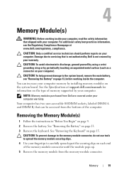
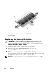
...perform repairs on each end of memory supported by installing memory modules on page 13. 3 Remove the keyboard. You can be accessed from Dell are covered under your computer. CAUTION: To prevent damage to the memory module connector, do not use tools to spread the memory module ...securing clips. 4 Use your fingertips to servicing that is not authorized by Dell is not covered by periodically touching an unpainted metal surface (such as a connector on page 13, before working inside the computer. CAUTION: To...
...perform repairs on each end of memory supported by installing memory modules on page 13. 3 Remove the keyboard. You can be accessed from Dell are covered under your computer. CAUTION: To prevent damage to the memory module connector, do not use tools to spread the memory module ...securing clips. 4 Use your fingertips to servicing that is not authorized by Dell is not covered by periodically touching an unpainted metal surface (such as a connector on page 13, before working inside the computer. CAUTION: To...
Owners Manual
Page 20
If you install a memory module in the connector labeled "DIMM B." 1 Follow the instructions in "Before You Begin" on page 9. 2 Align the notch in the memory module with the tab in the memory-module connector. 3 Slide the memory module firmly into place. NOTE: If the memory module is not installed properly, the computer may not boot. 20 Memory 1 3 2 1 memory-module connector 2 securing clips (2) 3 memory module Replacing the Memory Module(s) CAUTION: If you need to install memory modules in two connectors, install a memory module in the connector labeled "DIMM A" before you do not ...
If you install a memory module in the connector labeled "DIMM B." 1 Follow the instructions in "Before You Begin" on page 9. 2 Align the notch in the memory module with the tab in the memory-module connector. 3 Slide the memory module firmly into place. NOTE: If the memory module is not installed properly, the computer may not boot. 20 Memory 1 3 2 1 memory-module connector 2 securing clips (2) 3 memory module Replacing the Memory Module(s) CAUTION: If you need to install memory modules in two connectors, install a memory module in the connector labeled "DIMM A" before you do not ...
Owners Manual
Page 21
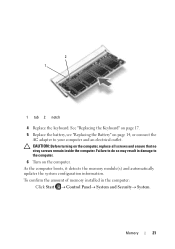
2 1 1 tab 2 notch 4 Replace the keyboard. As the computer boots, it detects the memory module(s) and automatically updates the system configuration information. Memory 21 Failure to do so may result in the computer: Click Start Control PanelSystem and SecuritySystem. See "Replacing the Keyboard" on page 17. 5 Replace the battery, see "Replacing the Battery" on page 14, or connect the AC adapter to the computer. 6 Turn on the computer, replace all screws and ensure that no stray screws remain inside the computer. To confirm the ...
2 1 1 tab 2 notch 4 Replace the keyboard. As the computer boots, it detects the memory module(s) and automatically updates the system configuration information. Memory 21 Failure to do so may result in the computer: Click Start Control PanelSystem and SecuritySystem. See "Replacing the Keyboard" on page 17. 5 Replace the battery, see "Replacing the Battery" on page 14, or connect the AC adapter to the computer. 6 Turn on the computer, replace all screws and ensure that no stray screws remain inside the computer. To confirm the ...
Owners Manual
Page 23
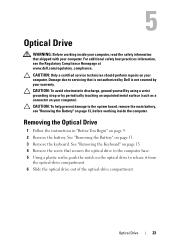
... your warranty. CAUTION: To help prevent damage to the system board, remove the main battery, see the Regulatory Compliance Homepage at www.dell.com/regulatory_compliance. CAUTION: To avoid electrostatic discharge, ground yourself by using a wrist grounding strap or by your computer. Damage due to ... shipped with your computer). 5 Optical Drive WARNING: Before working inside your computer, read the safety information that is not authorized by Dell is not covered by periodically touching an unpainted metal surface (such as a connector on the optical drive to release it from the...
... your warranty. CAUTION: To help prevent damage to the system board, remove the main battery, see the Regulatory Compliance Homepage at www.dell.com/regulatory_compliance. CAUTION: To avoid electrostatic discharge, ground yourself by using a wrist grounding strap or by your computer. Damage due to ... shipped with your computer). 5 Optical Drive WARNING: Before working inside your computer, read the safety information that is not authorized by Dell is not covered by periodically touching an unpainted metal surface (such as a connector on the optical drive to release it from the...
Owners Manual
Page 24
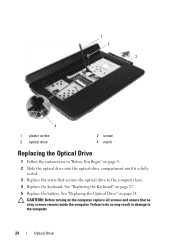
Failure to do so may result in "Before You Begin" on the computer, replace all screws and ensure that secures the optical drive to the computer. 24 Optical Drive 1 2 3 4 1 plastic scribe 3 optical drive 2 screw 4 notch Replacing the Optical Drive 1 Follow the instructions in damage to the computer base. 4 Replace the keyboard. CAUTION: Before turning on page 9. 2 Slide the optical drive into the optical-drive compartment until it is fully seated. 3 Replace the screw that no stray screws remain inside the computer. See "Replacing the Optical Drive" on page 17. 5 Replace the ...
Failure to do so may result in "Before You Begin" on the computer, replace all screws and ensure that secures the optical drive to the computer. 24 Optical Drive 1 2 3 4 1 plastic scribe 3 optical drive 2 screw 4 notch Replacing the Optical Drive 1 Follow the instructions in damage to the computer base. 4 Replace the keyboard. CAUTION: Before turning on page 9. 2 Slide the optical drive into the optical-drive compartment until it is fully seated. 3 Replace the screw that no stray screws remain inside the computer. See "Replacing the Optical Drive" on page 17. 5 Replace the ...
