Owners Manual
Page 3
Contents 1 Before You Begin 9 Recommended Tools 9 Turning Off Your Computer 9 Before Working Inside Your Computer 10 2 Battery 13 Removing the Battery 13 Replacing the Battery 14 3 Keyboard 15 Removing the Keyboard 15 Replacing the Keyboard 17 4 Memory Module(s 19 Removing the Memory Module(s 19 Replacing the Memory Module(s 20 5 Optical Drive 23 Removing the Optical Drive 23 Contents 3
Contents 1 Before You Begin 9 Recommended Tools 9 Turning Off Your Computer 9 Before Working Inside Your Computer 10 2 Battery 13 Removing the Battery 13 Replacing the Battery 14 3 Keyboard 15 Removing the Keyboard 15 Replacing the Keyboard 17 4 Memory Module(s 19 Removing the Memory Module(s 19 Replacing the Memory Module(s 20 5 Optical Drive 23 Removing the Optical Drive 23 Contents 3
Owners Manual
Page 4
Replacing the Optical Drive 24 6 Wireless Mini-Card 25 Removing the Mini-Card 25 Replacing the Mini-Card 27 7 Palm-Rest Assembly 29 Removing the Palm-Rest Assembly 29 Replacing the Palm-Rest Assembly 32 8 Power Button Board 35 Removing the Power Button Board 35 Replacing the Power Button Board 36 9 Hard Drive 37 Removing the Hard Drive 37 Replacing the Hard Drive 39 10 Coin-Cell Battery 41 Removing the Coin-Cell Battery 41 Replacing the Coin-Cell Battery 42 4 Contents
Replacing the Optical Drive 24 6 Wireless Mini-Card 25 Removing the Mini-Card 25 Replacing the Mini-Card 27 7 Palm-Rest Assembly 29 Removing the Palm-Rest Assembly 29 Replacing the Palm-Rest Assembly 32 8 Power Button Board 35 Removing the Power Button Board 35 Replacing the Power Button Board 36 9 Hard Drive 37 Removing the Hard Drive 37 Replacing the Hard Drive 39 10 Coin-Cell Battery 41 Removing the Coin-Cell Battery 41 Replacing the Coin-Cell Battery 42 4 Contents
Owners Manual
Page 14
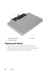
3 2 1 1 battery release latch 3 battery lock latch 2 battery Replacing the Battery 1 Follow the instructions in "Before You Begin" on page 9. 2 Slide the battery into the battery bay until it clicks into place. 3 Slide the battery lock latch to the lock position. 14 Battery
3 2 1 1 battery release latch 3 battery lock latch 2 battery Replacing the Battery 1 Follow the instructions in "Before You Begin" on page 9. 2 Slide the battery into the battery bay until it clicks into place. 3 Slide the battery lock latch to the lock position. 14 Battery
Owners Manual
Page 15
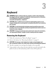
For additional safety best practices information, see "Removing the Battery" on page 13, before working inside the computer. CAUTION: To help prevent damage to replace. Be careful when removing and handling the keyboard. 3 Turn the computer over and open the display as far as a connector on ... perform repairs on the keyboard are fragile, easily dislodged, and time-consuming to the system board, remove the main battery, see the Regulatory Compliance Homepage at www.dell.com/regulatory_compliance. Damage due to the palm rest and ease the keyboard up until it clears off the palm rest....
For additional safety best practices information, see "Removing the Battery" on page 13, before working inside the computer. CAUTION: To help prevent damage to replace. Be careful when removing and handling the keyboard. 3 Turn the computer over and open the display as far as a connector on ... perform repairs on the keyboard are fragile, easily dislodged, and time-consuming to the system board, remove the main battery, see the Regulatory Compliance Homepage at www.dell.com/regulatory_compliance. Damage due to the palm rest and ease the keyboard up until it clears off the palm rest....
Owners Manual
Page 17
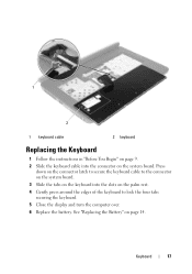
See "Replacing the Battery" on the palm rest. 4 Gently press around the edges of the keyboard to lock the four tabs securing the keyboard. 5 Close the display and turn the computer over. 6 Replace the battery. Keyboard 17 Press down on the connector latch to secure the keyboard cable to the connector on the system board. 3 Slide the tabs on the keyboard into the connector on the system board. 1 2 1 keyboard cable 2 keyboard Replacing the Keyboard 1 Follow the instructions in "Before You Begin" on page 9. 2 Slide the keyboard cable into the slots on page 14.
See "Replacing the Battery" on the palm rest. 4 Gently press around the edges of the keyboard to lock the four tabs securing the keyboard. 5 Close the display and turn the computer over. 6 Replace the battery. Keyboard 17 Press down on the connector latch to secure the keyboard cable to the connector on the system board. 3 Slide the tabs on the keyboard into the connector on the system board. 1 2 1 keyboard cable 2 keyboard Replacing the Keyboard 1 Follow the instructions in "Before You Begin" on page 9. 2 Slide the keyboard cable into the slots on page 14.
Owners Manual
Page 21
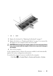
... boots, it detects the memory module(s) and automatically updates the system configuration information. Memory 21 2 1 1 tab 2 notch 4 Replace the keyboard. To confirm the amount of memory installed in damage to your computer and an electrical outlet. Failure to do so may...Click Start Control PanelSystem and SecuritySystem. CAUTION: Before turning on the computer. See "Replacing the Keyboard" on page 17. 5 Replace the battery, see "Replacing the Battery" on page 14, or connect the AC adapter to the computer. 6 Turn on the computer...
... boots, it detects the memory module(s) and automatically updates the system configuration information. Memory 21 2 1 1 tab 2 notch 4 Replace the keyboard. To confirm the amount of memory installed in damage to your computer and an electrical outlet. Failure to do so may...Click Start Control PanelSystem and SecuritySystem. CAUTION: Before turning on the computer. See "Replacing the Keyboard" on page 17. 5 Replace the battery, see "Replacing the Battery" on page 14, or connect the AC adapter to the computer. 6 Turn on the computer...
Owners Manual
Page 24
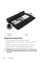
...drive compartment until it is fully seated. 3 Replace the screw that no stray screws remain inside the computer. 1 2 3 4 1 plastic scribe 3 optical drive 2 screw 4 notch Replacing the Optical Drive 1 Follow the instructions in ...damage to the computer base. 4 Replace the keyboard. CAUTION: Before turning on page 24. See "Replacing the Optical Drive" on the computer, replace all screws and ensure that secures the optical drive to the computer. 24 Optical Drive See "Replacing the Keyboard" on page 17. 5 Replace the battery...
...drive compartment until it is fully seated. 3 Replace the screw that no stray screws remain inside the computer. 1 2 3 4 1 plastic scribe 3 optical drive 2 screw 4 notch Replacing the Optical Drive 1 Follow the instructions in ...damage to the computer base. 4 Replace the keyboard. CAUTION: Before turning on page 24. See "Replacing the Optical Drive" on the computer, replace all screws and ensure that secures the optical drive to the computer. 24 Optical Drive See "Replacing the Keyboard" on page 17. 5 Replace the battery...
Owners Manual
Page 28
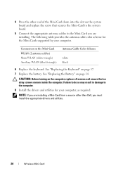
... The following table provides the antenna cable color scheme for your computer. See "Replacing the Keyboard" on page 14. See "Replacing the Battery" on page 17. 7 Replace the battery. CAUTION: Before turning on the computer, replace all screws and ensure that secures the Mini-Card to the system board. 5...result in damage to the Mini-Card you must install the appropriate drivers and utilities. 28 Wireless Mini-Card 4 Press the other than Dell, you are installing. Connectors on the Mini-Card WLAN (2 antenna cables) Main WLAN (white triangle) Auxiliary WLAN (black triangle) ...
... The following table provides the antenna cable color scheme for your computer. See "Replacing the Keyboard" on page 14. See "Replacing the Battery" on page 17. 7 Replace the battery. CAUTION: Before turning on the computer, replace all screws and ensure that secures the Mini-Card to the system board. 5...result in damage to the Mini-Card you must install the appropriate drivers and utilities. 28 Wireless Mini-Card 4 Press the other than Dell, you are installing. Connectors on the Mini-Card WLAN (2 antenna cables) Main WLAN (white triangle) Auxiliary WLAN (black triangle) ...

Owners Manual
Page 33
7 Replace the 11 screws that no stray screws remain inside the computer. CAUTION: Before turning on page 14. Palm-Rest Assembly 33 See "Replacing the Battery" on the computer, replace all screws and ensure that secure the palm-rest assembly to the computer. Failure to do so may result in damage to the computer base. 8 Replace the battery.
7 Replace the 11 screws that no stray screws remain inside the computer. CAUTION: Before turning on page 14. Palm-Rest Assembly 33 See "Replacing the Battery" on the computer, replace all screws and ensure that secure the palm-rest assembly to the computer. Failure to do so may result in damage to the computer base. 8 Replace the battery.
Owners Manual
Page 36
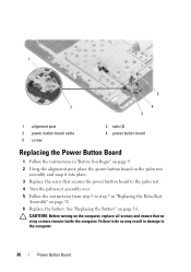
Failure to do so may result in damage to step 7 in "Replacing the Palm-Rest Assembly" on page 32. 6 Replace the battery. CAUTION: Before turning on the computer, replace all screws and ensure that secures the power button board to the palm rest. 4 Turn the palm-rest assembly.... 5 Follow the instructions from step 3 to the computer. 36 Power Button Board See "Replacing the Battery" on page 14. 1 5 2 4 3 1 alignment post 3 power-button board cable 5 screw 2 tabs (2) 4 power button board Replacing the Power Button Board 1 Follow the instructions in "Before You Begin" on page 9. 2...
Failure to do so may result in damage to step 7 in "Replacing the Palm-Rest Assembly" on page 32. 6 Replace the battery. CAUTION: Before turning on the computer, replace all screws and ensure that secures the power button board to the palm rest. 4 Turn the palm-rest assembly.... 5 Follow the instructions from step 3 to the computer. 36 Power Button Board See "Replacing the Battery" on page 14. 1 5 2 4 3 1 alignment post 3 power-button board cable 5 screw 2 tabs (2) 4 power button board Replacing the Power Button Board 1 Follow the instructions in "Before You Begin" on page 9. 2...
Owners Manual
Page 39
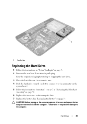
... Push the hard drive towards the left to connect it to the connector on the system board. 5 Follow the instructions from its packaging. See "Replacing the Battery" on the computer, replace all screws and ensure that no stray screws remain inside the computer. Hard Drive 39 1 1 hard drive... Replacing the Hard Drive 1 Follow the instructions in "Before You Begin" on page 9. 2 Remove the new hard drive from step 3 to step 7 in damage to the computer base. 7 Replace the battery. Failure to do so may result in "Replacing the Palm-Rest Assembly" on page 32...
... Push the hard drive towards the left to connect it to the connector on the system board. 5 Follow the instructions from its packaging. See "Replacing the Battery" on the computer, replace all screws and ensure that no stray screws remain inside the computer. Hard Drive 39 1 1 hard drive... Replacing the Hard Drive 1 Follow the instructions in "Before You Begin" on page 9. 2 Remove the new hard drive from step 3 to step 7 in damage to the computer base. 7 Replace the battery. Failure to do so may result in "Replacing the Palm-Rest Assembly" on page 32...

Owners Manual
Page 42
... instructions from step 3 to the computer. 42 Coin-Cell Battery See "Replacing the Battery" on the computer, replace all screws and ensure that no stray screws remain inside the computer. CAUTION: Before turning on page 14. 1 2 1 plastic scribe 2 coin-cell battery Replacing the Coin-Cell Battery 1 Follow the instructions in "Replacing the Palm-Rest Assembly" on page 32...
... instructions from step 3 to the computer. 42 Coin-Cell Battery See "Replacing the Battery" on the computer, replace all screws and ensure that no stray screws remain inside the computer. CAUTION: Before turning on page 14. 1 2 1 plastic scribe 2 coin-cell battery Replacing the Coin-Cell Battery 1 Follow the instructions in "Replacing the Palm-Rest Assembly" on page 32...
Owners Manual
Page 44
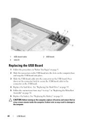
...Before turning on page 14. Press down on the connector latch to secure the USB-board cable to step 7 in "Replacing the Palm-Rest Assembly" on page 32. 6 Replace the battery. Failure to do so may result in "Before You Begin" on page 9. 2 Slide the connectors on the USB ... 3 tabs (2) 2 USB board Replacing the USB Board 1 Follow the procedures in damage to the computer. 44 USB Board See "Replacing the Hard Drive" on page 39. 5 Follow the instructions from step 3 to the connector on the USB board. See "Replacing the Battery" on the computer, replace all screws and ensure that no...
...Before turning on page 14. Press down on the connector latch to secure the USB-board cable to step 7 in "Replacing the Palm-Rest Assembly" on page 32. 6 Replace the battery. Failure to do so may result in "Before You Begin" on page 9. 2 Slide the connectors on the USB ... 3 tabs (2) 2 USB board Replacing the USB Board 1 Follow the procedures in damage to the computer. 44 USB Board See "Replacing the Hard Drive" on page 39. 5 Follow the instructions from step 3 to the connector on the USB board. See "Replacing the Battery" on the computer, replace all screws and ensure that no...

Owners Manual
Page 46
See "Replacing the Battery" on the computer, replace all screws and ensure that no stray screws remain inside the computer. Failure to the computer. 46 Thermal Cooling Assembly 4 3 2 1 1 captive screws (4) 3 fan cable 2 thermal cooling assembly 4 display cable Replacing the Thermal Cooling Assembly 1 Follow the instructions in "Before You Begin" on page 9. ... the connector on the system board. 5 Follow the instructions from step 3 to step 7 in damage to do so may result in "Replacing the Palm-Rest Assembly" on page 32. 6 Replace the battery. CAUTION: Before turning on page 14.
See "Replacing the Battery" on the computer, replace all screws and ensure that no stray screws remain inside the computer. Failure to the computer. 46 Thermal Cooling Assembly 4 3 2 1 1 captive screws (4) 3 fan cable 2 thermal cooling assembly 4 display cable Replacing the Thermal Cooling Assembly 1 Follow the instructions in "Before You Begin" on page 9. ... the connector on the system board. 5 Follow the instructions from step 3 to step 7 in damage to do so may result in "Replacing the Palm-Rest Assembly" on page 32. 6 Replace the battery. CAUTION: Before turning on page 14.
Owners Manual
Page 49
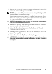
... step 3 to step 7 in damage to the system board. 4 Replace the thermal cooling assembly. Failure to do so may result in "Replacing the Palm-Rest Assembly" on page 32. 6 Replace the battery. When the processor module is not seated properly. Processor Module (For Inspiron 15-N5050/15-N5040 Only) 49 CAUTION: To avoid damage to the...
... step 3 to step 7 in damage to the system board. 4 Replace the thermal cooling assembly. Failure to do so may result in "Replacing the Palm-Rest Assembly" on page 32. 6 Replace the battery. When the processor module is not seated properly. Processor Module (For Inspiron 15-N5050/15-N5040 Only) 49 CAUTION: To avoid damage to the...
Owners Manual
Page 53
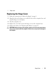
See "Replacing the Battery" on the computer, replace all screws and ensure that secures the hinge cover to the computer base. 5 Replace the battery. Failure to do so may result in "Before You Begin" on page 9. 2 Align the tabs on the hinge cover with the slots on the computer base and snap the hinge cover into place. 3 Turn the computer over. 4 Replace the screw that no stray screws remain inside the computer. Hinge Cover 53 CAUTION: Before turning on page 14. 1 hinge cover Replacing the Hinge Cover 1 Follow the instructions in damage to the computer.
See "Replacing the Battery" on the computer, replace all screws and ensure that secures the hinge cover to the computer base. 5 Replace the battery. Failure to do so may result in "Before You Begin" on page 9. 2 Align the tabs on the hinge cover with the slots on the computer base and snap the hinge cover into place. 3 Turn the computer over. 4 Replace the screw that no stray screws remain inside the computer. Hinge Cover 53 CAUTION: Before turning on page 14. 1 hinge cover Replacing the Hinge Cover 1 Follow the instructions in damage to the computer.

Owners Manual
Page 59
CAUTION: Before turning on page 14. See "Replacing the Battery" on the computer, replace all screws and ensure that no stray screws remain inside edge of the display bezel. 4 Remove the display bezel. 1 1 display bezel Display 59 See "Removing ... 55. CAUTION: The display bezel is extremely fragile. Failure to prevent damaging the display bezel. 3 Using your fingertips, carefully pry up the inside the computer. 8 Replace the two screws to the computer. Display Bezel Removing the Display Bezel 1 Follow the instructions in damage to the computer base...
CAUTION: Before turning on page 14. See "Replacing the Battery" on the computer, replace all screws and ensure that no stray screws remain inside edge of the display bezel. 4 Remove the display bezel. 1 1 display bezel Display 59 See "Removing ... 55. CAUTION: The display bezel is extremely fragile. Failure to prevent damaging the display bezel. 3 Using your fingertips, carefully pry up the inside the computer. 8 Replace the two screws to the computer. Display Bezel Removing the Display Bezel 1 Follow the instructions in damage to the computer base...

Owners Manual
Page 66
... remain inside the computer. CAUTION: Before turning on page 60. 5 Replace the display assembly. See "Replacing the Display Assembly" on page 14. 4 3 2 1 1 display cover 3 camera module 2 tabs (2) 4 camera cable Replacing the Camera Module 1 Follow the instructions in "Replacing the Palm-Rest Assembly" on page 32. 8 Replace the battery. See "Replacing the Battery" on page 58. 6 Replace the hinge cover.
... remain inside the computer. CAUTION: Before turning on page 60. 5 Replace the display assembly. See "Replacing the Display Assembly" on page 14. 4 3 2 1 1 display cover 3 camera module 2 tabs (2) 4 camera cable Replacing the Camera Module 1 Follow the instructions in "Replacing the Palm-Rest Assembly" on page 32. 8 Replace the battery. See "Replacing the Battery" on page 58. 6 Replace the hinge cover.
Owners Manual
Page 70
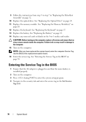
... page 20. 12 Replace the keyboard. See "Replacing the Battery" on page 14. 14 Replace any removed cards or blanks in the 3-in the BIOS" on page 70. NOTE: After you have replaced the system board, enter the computer Service Tag into the BIOS of the replacement system board. 16 Enter... Follow the instructions from step 3 to the computer. 15 Turn on the computer. See "Replacing the Memory Module(s)" on page 17. 13 Replace the battery. CAUTION: Before turning on the computer, replace all screws and ensure that the main battery is plugged in the Set Service Tag field. 70 System Board See...
... page 20. 12 Replace the keyboard. See "Replacing the Battery" on page 14. 14 Replace any removed cards or blanks in the 3-in the BIOS" on page 70. NOTE: After you have replaced the system board, enter the computer Service Tag into the BIOS of the replacement system board. 16 Enter... Follow the instructions from step 3 to the computer. 15 Turn on the computer. See "Replacing the Memory Module(s)" on page 17. 13 Replace the battery. CAUTION: Before turning on the computer, replace all screws and ensure that the main battery is plugged in the Set Service Tag field. 70 System Board See...


