Product Manual
Page 3
... Password Settings...20 SNMP Settings ...21 i Table of Contents D-Link Web Smart Switch User Manual Table of Contents Table of Contents ...i About This Guide...1 Terms/Usage...1 Copyright and Trademarks ...1 Product Introduction ...2 DES-1210-08P ...3 Front Panel ...3 Rear Panel...3 DES-1210-28 ...3 Front Panel ...3 Rear Panel...4 DES-1210-28P ...4 Front Panel ...4 Rear Panel...5 DES-1210-52 ...5 Front Panel ...5 Rear Panel...6 Hardware Installation ...7 Step 1: Unpacking...
... Password Settings...20 SNMP Settings ...21 i Table of Contents D-Link Web Smart Switch User Manual Table of Contents Table of Contents ...i About This Guide...1 Terms/Usage...1 Copyright and Trademarks ...1 Product Introduction ...2 DES-1210-08P ...3 Front Panel ...3 Rear Panel...3 DES-1210-28 ...3 Front Panel ...3 Rear Panel...4 DES-1210-28P ...4 Front Panel ...4 Rear Panel...5 DES-1210-52 ...5 Front Panel ...5 Rear Panel...6 Hardware Installation ...7 Step 1: Unpacking...
Product Manual
Page 4
...Link Web Smart Switch User Manual System Settings...22 Web-based Management...23 Tool Bar > Save Menu ...24 Save Configuration ...24 Save Log ...24 Tool Bar > Tool Menu ...24 Reset ...24 Reset System ...24 Reboot Device ...25 Configuration Backup & Restore ...25 Firmware Backup and Upload ...25 Tool Bar > Smart...Configuration > Link Aggregation > Port Trunking 41 Configuration > Link Aggregation > LACP Port Settings 42 Configuration > IGMP Snooping ...43 Configuration > Multicast Filtering Mode (For DES-1210-08P only 44 Configuration > Multicast Filtering Mode (For DES-1210-28/28P/52 45 ...
...Link Web Smart Switch User Manual System Settings...22 Web-based Management...23 Tool Bar > Save Menu ...24 Save Configuration ...24 Save Log ...24 Tool Bar > Tool Menu ...24 Reset ...24 Reset System ...24 Reboot Device ...25 Configuration Backup & Restore ...25 Firmware Backup and Upload ...25 Tool Bar > Smart...Configuration > Link Aggregation > Port Trunking 41 Configuration > Link Aggregation > LACP Port Settings 42 Configuration > IGMP Snooping ...43 Configuration > Multicast Filtering Mode (For DES-1210-08P only 44 Configuration > Multicast Filtering Mode (For DES-1210-28/28P/52 45 ...
Product Manual
Page 5
... ...75 Port Functions ...75 Physical & Environment ...75 Emission (EMI) Certifications ...75 Safety Certifications...75 Features ...75 iii Table of Contents D-Link Web Smart Switch User Manual Security > Trusted Host...53 Security > Safeguard Engine...53 Security > ARP Spoofing Prevention ...53 Security > Port Security...54 Security >...> PoE Port Settings (Only for DES-1210-08P/28P 64 PoE > PoE System Settings (Only for DES-1210-08P/28P 65 Time-Based PoE > Time Range Settings (Only for DES-1210-08P/28P 66 LLDP > LLDP Global Settings (Only for DES-1210-08P/28P 66 LLDP > LLDP Remote...
... ...75 Port Functions ...75 Physical & Environment ...75 Emission (EMI) Certifications ...75 Safety Certifications...75 Features ...75 iii Table of Contents D-Link Web Smart Switch User Manual Security > Trusted Host...53 Security > Safeguard Engine...53 Security > ARP Spoofing Prevention ...53 Security > Port Security...54 Security >...> PoE Port Settings (Only for DES-1210-08P/28P 64 PoE > PoE System Settings (Only for DES-1210-08P/28P 65 Time-Based PoE > Time Range Settings (Only for DES-1210-08P/28P 66 LLDP > LLDP Global Settings (Only for DES-1210-08P/28P 66 LLDP > LLDP Remote...
Product Manual
Page 6
Rack mount Instructions ...77 iv Table of Contents D-Link Web Smart Switch User Manual L2 Features ...75 VLAN ...75 QoS (Quality of Service)...76 Security...76 Green...76 Management...76 Appendix C -
Rack mount Instructions ...77 iv Table of Contents D-Link Web Smart Switch User Manual L2 Features ...75 VLAN ...75 QoS (Quality of Service)...76 Security...76 Green...76 Management...76 Appendix C -
Product Manual
Page 7
... Manual About This Guide This guide provides instructions to install the D-Link Fast Ethernet Web Smart Switch DES-121008P/28/28P/52, how to use of D-Link Corporation is strictly forbidden. This guide is subjected to the Product Instruction and Technical Specification sections for detailed information about the function descriptions and configuration ...
... Manual About This Guide This guide provides instructions to install the D-Link Fast Ethernet Web Smart Switch DES-121008P/28/28P/52, how to use of D-Link Corporation is strictly forbidden. This guide is subjected to the Product Instruction and Technical Specification sections for detailed information about the function descriptions and configuration ...
Product Manual
Page 8
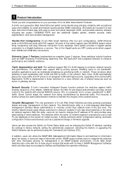
...devices. The new generation of D-Link Web Smart Switches provides growing businesses simple and easy management of abnormal events. It allows extensive switch configuration setting, and basic configuration of D-Link Web Smart Switch Products. D-Link Web Smart Switches offer four port configurations, 24/48...Ethernet connection to change or firmware upgrade. These functions allow switches to discover multiple D-Link web smart switches in the network. 1 Product Introduction D-Link Web Smart Switch User Manual 1 Product Introduction Thank you and congratulations on the screen for...
...devices. The new generation of D-Link Web Smart Switches provides growing businesses simple and easy management of abnormal events. It allows extensive switch configuration setting, and basic configuration of D-Link Web Smart Switch Products. D-Link Web Smart Switches offer four port configurations, 24/48...Ethernet connection to change or firmware upgrade. These functions allow switches to discover multiple D-Link web smart switches in the network. 1 Product Introduction D-Link Web Smart Switch User Manual 1 Product Introduction Thank you and congratulations on the screen for...
Product Manual
Page 9
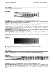
... (1-8): The PoE LED lights up with solid green indicates power device is connected to the port. Rear Panel Figure 2 - 1 Product Introduction DES-1210-08P 8-Port 10/100Mpbs PoE Web Smart Switch Front Panel D-Link Web Smart Switch User Manual Figure 1 - Port Speed LED (1-8): The Port Speed LED lights up with solid green indicate the corresponding port is connected to...
... (1-8): The PoE LED lights up with solid green indicates power device is connected to the port. Rear Panel Figure 2 - 1 Product Introduction DES-1210-08P 8-Port 10/100Mpbs PoE Web Smart Switch Front Panel D-Link Web Smart Switch User Manual Figure 1 - Port Speed LED (1-8): The Port Speed LED lights up with solid green indicate the corresponding port is connected to...
Product Manual
Page 10
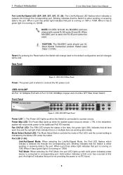
...100/1000Mbps Copper and 2 Combo SFP Web Smart Switch Front Panel Figure 5 - When it has a green light it is running on or multiple fans are shared with normal RJ-45 ports 25 and 26. 1 Product Introduction D-Link Web Smart Switch User Manual Port Link/Act/Speed LED (25F, 26F, 25T..., 26T, 27, 28): The Link/Act/Speed LED flashes which indicate a network link through the corresponding port. Blinking indicates that the Switch is where to the port. Blinking indicates that on 10M or 100M. DES-1210-28...
...100/1000Mbps Copper and 2 Combo SFP Web Smart Switch Front Panel Figure 5 - When it has a green light it is running on or multiple fans are shared with normal RJ-45 ports 25 and 26. 1 Product Introduction D-Link Web Smart Switch User Manual Port Link/Act/Speed LED (25F, 26F, 25T..., 26T, 27, 28): The Link/Act/Speed LED flashes which indicate a network link through the corresponding port. Blinking indicates that the Switch is where to the port. Blinking indicates that on 10M or 100M. DES-1210-28...
Product Manual
Page 11
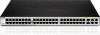
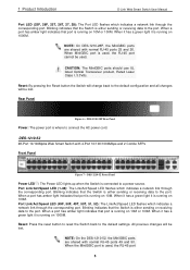
...the default settings. When a port has amber light indicates that the Switch is running on 10M or 100M. DES-1210-52 48-Port 10/100Mpbs Web Smart Switch with normal RJ-45 ports 25 and 26. 1 Product Introduction D-Link Web Smart Switch User Manual Port LED (25F, 26F, 25T, 26T, 27, ...28): The Port LED flashes which indicates a network link through the corresponding port. ...
...the default settings. When a port has amber light indicates that the Switch is running on 10M or 100M. DES-1210-52 48-Port 10/100Mpbs Web Smart Switch with normal RJ-45 ports 25 and 26. 1 Product Introduction D-Link Web Smart Switch User Manual Port LED (25F, 26F, 25T, 26T, 27, ...28): The Port LED flashes which indicates a network link through the corresponding port. ...
Product Manual
Page 12
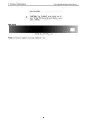
DES-1210-52 Rear Panel Power: Connect the supplied AC power cable to this port. 6 Figure 8 - 1 Product Introduction D-Link Web Smart Switch User Manual Rear Panel cannot be used. CAUTION: The MiniGBIC ports should use UL listed Optical Transceiver product, Rated Laser Class I. 3.3Vdc.
DES-1210-52 Rear Panel Power: Connect the supplied AC power cable to this port. 6 Figure 8 - 1 Product Introduction D-Link Web Smart Switch User Manual Rear Panel cannot be used. CAUTION: The MiniGBIC ports should use UL listed Optical Transceiver product, Rated Laser Class I. 3.3Vdc.
Product Manual
Page 13
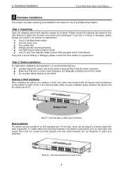
... D-View Module If any item is found missing or damaged, please contact the local reseller for the D-Link Web-Smart Switch. 2 Hardware Installation D-Link Web Smart Switch User Manual 2 Hardware Installation This chapter provides unpacking and installation information for replacement. One D-Link Web-Smart Switch One AC power cord Four rubber feet Screws and two mounting brackets One Multi-lingual Getting Started...
... D-View Module If any item is found missing or damaged, please contact the local reseller for the D-Link Web-Smart Switch. 2 Hardware Installation D-Link Web Smart Switch User Manual 2 Hardware Installation This chapter provides unpacking and installation information for replacement. One D-Link Web-Smart Switch One AC power cord Four rubber feet Screws and two mounting brackets One Multi-lingual Getting Started...
Product Manual
Page 14
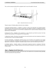
...unit rack assembly, the operating ambient temperature of the rack environment may now connect the AC power cord into the rear of the switch and to the branch circuit (e.g. C) Mechanical Loading - Consideration should be aware of following safety Instructions when installing: A) Elevated Operating... of the equipment in the rack. Particular attention should be given to mount the switch in a rack should be such that a hazardous condition is grounded and surge protected). 8 2 Hardware Installation D-Link Web Smart Switch User Manual Then, use of power strips)."
...unit rack assembly, the operating ambient temperature of the rack environment may now connect the AC power cord into the rear of the switch and to the branch circuit (e.g. C) Mechanical Loading - Consideration should be aware of following safety Instructions when installing: A) Elevated Operating... of the equipment in the rack. Particular attention should be given to mount the switch in a rack should be such that a hazardous condition is grounded and surge protected). 8 2 Hardware Installation D-Link Web Smart Switch User Manual Then, use of power strips)."
Product Manual
Page 15
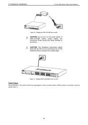
...Hardware Installation D-Link Web Smart Switch User Manual Figure 12 - When power is to be unplugged in . 9 CAUTION: The installation instructions clearly state that the ITE is resumed, plug the switch back in case of DES-1210-08P before power cables are connected. Plugging DES-1210-28/28P/52 into an outlet... CAUTION: Do not turn on the power switch of power failure. Plugging the DES-1210-08P into an outlet Power Failure As ...
...Hardware Installation D-Link Web Smart Switch User Manual Figure 12 - When power is to be unplugged in . 9 CAUTION: The installation instructions clearly state that the ITE is resumed, plug the switch back in case of DES-1210-08P before power cables are connected. Plugging DES-1210-28/28P/52 into an outlet... CAUTION: Do not turn on the power switch of power failure. Plugging the DES-1210-08P into an outlet Power Failure As ...
Product Manual
Page 16
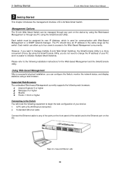
...Link Web Smart Switches, the SmartConsole Utility is used for the Web-based Management and the SmartConsole Utility. A PC with Web-Based Management or a SNMP network manager. 3 Getting Started D-Link Web Smart Switch User Manual 3 Getting Started This chapter introduces the management interface of the switch and to the Ethernet port on the front panel of D-Link Web-Smart Switch. Each switch... RJ-45 Ethernet connection 2. Figure 14 -Connected Ethernet cable 10 Management Options The D-Link Web Smart Switch can be assigned its own IP Address, which is a more convenient choice. However...
...Link Web Smart Switches, the SmartConsole Utility is used for the Web-based Management and the SmartConsole Utility. A PC with Web-Based Management or a SNMP network manager. 3 Getting Started D-Link Web Smart Switch User Manual 3 Getting Started This chapter introduces the management interface of the switch and to the Ethernet port on the front panel of D-Link Web-Smart Switch. Each switch... RJ-45 Ethernet connection 2. Figure 14 -Connected Ethernet cable 10 Management Options The D-Link Web Smart Switch can be assigned its own IP Address, which is a more convenient choice. However...

Product Manual
Page 17
..., the PC should have an IP address in the address bar. For example, if the switch has an IP address of the D-Link Web Smart Switch. The switch supports 9 languages including English, Traditional Chinese, Simplified Chinese, German, Spanish, French, Italian, Japanese...mask of the Webbased Management interface then click OK. The web configuration can also be sure to launch the Web-based Management, you through the SmartConsole Utility. 3 Getting Started D-Link Web Smart Switch User Manual Login Web-based Management In order to Chapter 5 Configuration for detailed instructions...
..., the PC should have an IP address in the address bar. For example, if the switch has an IP address of the D-Link Web Smart Switch. The switch supports 9 languages including English, Traditional Chinese, Simplified Chinese, German, Spanish, French, Italian, Japanese...mask of the Webbased Management interface then click OK. The web configuration can also be sure to launch the Web-based Management, you through the SmartConsole Utility. 3 Getting Started D-Link Web Smart Switch User Manual Login Web-based Management In order to Chapter 5 Configuration for detailed instructions...
Product Manual
Page 18
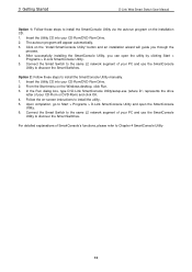
...on the installation CD. 1. For detailed explanations of your CD-Rom or DVD-Rom) and click OK. 4. 3 Getting Started D-Link Web Smart Switch User Manual Option 1: Follow these steps to install the SmartConsole Utility manually. 1. From the Start menu on the "Install SmartConsole ...Utility, you through the process. 4. In the Run dialog box, type D:\D-Link SmartConsole Utility\setup.exe (where D:\ represents the drive letter of SmartConsole's functions, please refer to discover the Smart Switches. Connect the Smart Switch to the same L2 network segment of your CD-Rom/DVD-Rom Drive. ...
...on the installation CD. 1. For detailed explanations of your CD-Rom or DVD-Rom) and click OK. 4. 3 Getting Started D-Link Web Smart Switch User Manual Option 1: Follow these steps to install the SmartConsole Utility manually. 1. From the Start menu on the "Install SmartConsole ...Utility, you through the process. 4. In the Run dialog box, type D:\D-Link SmartConsole Utility\setup.exe (where D:\ represents the drive letter of SmartConsole's functions, please refer to discover the Smart Switches. Connect the Smart Switch to the same L2 network segment of your CD-Rom/DVD-Rom Drive. ...
Product Manual
Page 19
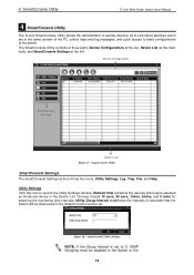
...secs, 30 secs, 1mins, 2mins, and 5 mins for selecting the monitoring time intervals. The SmartConsole Utility consists of the switch. Refresh time refreshes the devices which are in the same domain of the PC, collect traps and log messages, and quick... must be discovered in the Switch or the 13 Figure 18 - Device Configuration SmartConsole Settings Device List Figure 17 - 4 SmartConsole Utility D-Link Web Smart Switch User Manual 4 SmartConsole Utility The D-Link SmartConsole Utility allows the administrator to quickly discover all D-Link smart switches which were selected as the ...
...secs, 30 secs, 1mins, 2mins, and 5 mins for selecting the monitoring time intervals. The SmartConsole Utility consists of the switch. Refresh time refreshes the devices which are in the same domain of the PC, collect traps and log messages, and quick... must be discovered in the Switch or the 13 Figure 18 - Device Configuration SmartConsole Settings Device List Figure 17 - 4 SmartConsole Utility D-Link Web Smart Switch User Manual 4 SmartConsole Utility The D-Link SmartConsole Utility allows the administrator to quickly discover all D-Link smart switches which were selected as the ...
Product Manual
Page 20
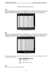
... it comes from and Status shows the content of the SmartConsole Utility and the device. Click View Log to exit. Figure 19 - 4 SmartConsole Utility D-Link Web Smart Switch User Manual Web-Smart Switch will change while receiving new trap messages. Please see below for detailed description. Click OK to show the events of this icon to exit...
... it comes from and Status shows the content of the SmartConsole Utility and the device. Click View Log to exit. Figure 19 - 4 SmartConsole Utility D-Link Web Smart Switch User Manual Web-Smart Switch will change while receiving new trap messages. Please see below for detailed description. Click OK to show the events of this icon to exit...
Product Manual
Page 21
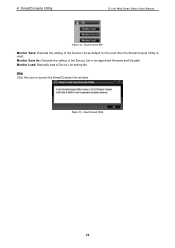
Monitor Save As: Records the setting of the Device List as default for the next time the SmartConsole Utility is used. Figure 22 - 4 SmartConsole Utility D-Link Web Smart Switch User Manual Figure 21 - Help Click this icon to launch the SmartConsole Info window. SmartConsole Help 15 Monitor Load: Manually load a Device List setting file. SmartConsole File Monitor Save: Records the setting of the Device List in an appointed filename and file path.
Monitor Save As: Records the setting of the Device List as default for the next time the SmartConsole Utility is used. Figure 22 - 4 SmartConsole Utility D-Link Web Smart Switch User Manual Figure 21 - Help Click this icon to launch the SmartConsole Info window. SmartConsole Help 15 Monitor Load: Manually load a Device List setting file. SmartConsole File Monitor Save: Records the setting of the Device List in an appointed filename and file path.
Product Manual
Page 22
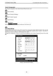
... the Product Name, IP Address, Gateway, Subnet Mask, System Name, Location, Trap Host IP, Switch Group Interval, and DHCP Client Setting of the Switch. To apply the configuration, insert the correct device password in the SmartConsole Utility has five icons: ...Device Settings Device Password Manager Multi Firmware Upgrade DHCP Refresh Web Access and the , , device buttons for the Device List. Device Settings Select a switch from the Device List. 4 SmartConsole Utility D-Link Web Smart Switch User Manual Device Configuration The Device Configuration in the Confirm Password...
... the Product Name, IP Address, Gateway, Subnet Mask, System Name, Location, Trap Host IP, Switch Group Interval, and DHCP Client Setting of the Switch. To apply the configuration, insert the correct device password in the SmartConsole Utility has five icons: ...Device Settings Device Password Manager Multi Firmware Upgrade DHCP Refresh Web Access and the , , device buttons for the Device List. Device Settings Select a switch from the Device List. 4 SmartConsole Utility D-Link Web Smart Switch User Manual Device Configuration The Device Configuration in the Confirm Password...


