Product Manual
Page 3
......20 SNMP Settings ...21 i Table of Contents D-Link Web Smart Switch User Manual Table of Contents Table of Contents ...i About This Guide...1 Terms/Usage...1 Copyright and Trademarks ...1 Product Introduction ...2 DES-1210-08P ...3 Front Panel ...3 Rear Panel...3 DES-1210-28 ...3 Front Panel ...3 Rear Panel...4 DES-1210-28P ...4 Front Panel ...4 Rear Panel...5 DES-1210-52 ...5 Front Panel ...5 Rear Panel...6 Hardware Installation ...7 Step...
......20 SNMP Settings ...21 i Table of Contents D-Link Web Smart Switch User Manual Table of Contents Table of Contents ...i About This Guide...1 Terms/Usage...1 Copyright and Trademarks ...1 Product Introduction ...2 DES-1210-08P ...3 Front Panel ...3 Rear Panel...3 DES-1210-28 ...3 Front Panel ...3 Rear Panel...4 DES-1210-28P ...4 Front Panel ...4 Rear Panel...5 DES-1210-52 ...5 Front Panel ...5 Rear Panel...6 Hardware Installation ...7 Step...
Product Manual
Page 4
Table of Contents D-Link Web Smart Switch User Manual System Settings...22 Web-based Management...23 Tool Bar > Save Menu ...24 Save Configuration ...24 Save Log ...24 Tool... > Auto Surveillance VLAN > Auto Surveillance VLAN Settings 40 Configuration > Link Aggregation > Port Trunking 41 Configuration > Link Aggregation > LACP Port Settings 42 Configuration > IGMP Snooping ...43 Configuration > Multicast Filtering Mode (For DES-1210-08P only 44 Configuration > Multicast Filtering Mode (For DES-1210-28/28P/52 45 Configuration > Port Mirroring ...45 Configuration > Loopback Detection ...45 ...
Table of Contents D-Link Web Smart Switch User Manual System Settings...22 Web-based Management...23 Tool Bar > Save Menu ...24 Save Configuration ...24 Save Log ...24 Tool... > Auto Surveillance VLAN > Auto Surveillance VLAN Settings 40 Configuration > Link Aggregation > Port Trunking 41 Configuration > Link Aggregation > LACP Port Settings 42 Configuration > IGMP Snooping ...43 Configuration > Multicast Filtering Mode (For DES-1210-08P only 44 Configuration > Multicast Filtering Mode (For DES-1210-28/28P/52 45 Configuration > Port Mirroring ...45 Configuration > Loopback Detection ...45 ...
Product Manual
Page 5
Table of Contents D-Link Web Smart Switch User Manual Security > Trusted Host...53 Security > Safeguard Engine...53 Security > ARP Spoofing Prevention ...53 Security > Port Security...54 Security > SSL Settings....../28P 65 Time-Based PoE > Time Range Settings (Only for DES-1210-08P/28P 66 LLDP > LLDP Global Settings (Only for DES-1210-08P/28P 66 LLDP > LLDP Remote Port Information (Only for DES-1210-08P/28P 67 LLDP > LLDP-MED Settings (Only for DES-1210-28P 68 Command Line Interface...69 To connect a switch via TELNET:...69...
Table of Contents D-Link Web Smart Switch User Manual Security > Trusted Host...53 Security > Safeguard Engine...53 Security > ARP Spoofing Prevention ...53 Security > Port Security...54 Security > SSL Settings....../28P 65 Time-Based PoE > Time Range Settings (Only for DES-1210-08P/28P 66 LLDP > LLDP Global Settings (Only for DES-1210-08P/28P 66 LLDP > LLDP Remote Port Information (Only for DES-1210-08P/28P 67 LLDP > LLDP-MED Settings (Only for DES-1210-28P 68 Command Line Interface...69 To connect a switch via TELNET:...69...
Product Manual
Page 6
Rack mount Instructions ...77 iv Table of Contents D-Link Web Smart Switch User Manual L2 Features ...75 VLAN ...75 QoS (Quality of Service)...76 Security...76 Green...76 Management...76 Appendix C -
Rack mount Instructions ...77 iv Table of Contents D-Link Web Smart Switch User Manual L2 Features ...75 VLAN ...75 QoS (Quality of Service)...76 Security...76 Green...76 Management...76 Appendix C -
Product Manual
Page 7
... Smart Switch User Manual About This Guide This guide provides instructions to install the D-Link Fast Ethernet Web Smart Switch DES-121008P/28/28P/52, how to use of D-Link Corporation; Microsoft and Windows are commonly accepted for basic switch installation and settings. 3. This guide is subjected to terms "switch", "bridge" and "switching hubs...
... Smart Switch User Manual About This Guide This guide provides instructions to install the D-Link Fast Ethernet Web Smart Switch DES-121008P/28/28P/52, how to use of D-Link Corporation; Microsoft and Windows are commonly accepted for basic switch installation and settings. 3. This guide is subjected to terms "switch", "bridge" and "switching hubs...
Product Manual
Page 8
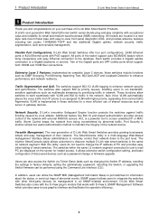
... access control of the network device. ACL is another simple but useful authentication method to screen unwanted IP or MAC traffic. D-Link's innovative Safeguard Engine function protects the switches against traffic flooding caused by abnormal traffic. Port Security is a powerful tool to maintain... server or gateway devices. SNMP support allows users to the port level. Storm Control keeps the network from normal traffic. D-Link's next generation Web Smart Ethernet switch series blends plug-and-play simplicity with other third-party devices for management in module that...
... access control of the network device. ACL is another simple but useful authentication method to screen unwanted IP or MAC traffic. D-Link's innovative Safeguard Engine function protects the switches against traffic flooding caused by abnormal traffic. Port Security is a powerful tool to maintain... server or gateway devices. SNMP support allows users to the port level. Storm Control keeps the network from normal traffic. D-Link's next generation Web Smart Ethernet switch series blends plug-and-play simplicity with other third-party devices for management in module that...
Product Manual
Page 9
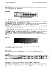
1 Product Introduction DES-1210-08P 8-Port 10/100Mpbs PoE Web Smart Switch Front Panel D-Link Web Smart Switch User Manual Figure 1 - PoE LED (1-8): The PoE LED lights up with solid green indicates power device is connected to a power source....the Switch is connected to the port. Rear Panel Figure 2 - Port Link/Act/Speed LED (1-24): The Link/Act/Speed LED flashes which indicates a network link through the corresponding port. DES-1210-28 24-Port 10/100Mpbs with solid green indicate a network link through the corresponding port. When a port has amber light indicates that the...
1 Product Introduction DES-1210-08P 8-Port 10/100Mpbs PoE Web Smart Switch Front Panel D-Link Web Smart Switch User Manual Figure 1 - PoE LED (1-8): The PoE LED lights up with solid green indicates power device is connected to a power source....the Switch is connected to the port. Rear Panel Figure 2 - Port Link/Act/Speed LED (1-24): The Link/Act/Speed LED flashes which indicates a network link through the corresponding port. DES-1210-28 24-Port 10/100Mpbs with solid green indicate a network link through the corresponding port. When a port has amber light indicates that the...
Product Manual
Page 10
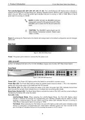
..., 26F, 25T, 26T, 27, 28): The Link/Act/Speed LED flashes which indicate a network link through the corresponding port. CAUTION: The MiniGBIC ports should use UL listed Optical Transceiver product, Rated Laser Class I. 3.3Vdc. When it has a green light it is running on 10M or 100M. DES-1210-28P 24-Port 10/100Mpbs PoE... with normal RJ-45 ports 25 and 26. When it has a green light it is not providing the power or no PD found. 4 Port LED (1-24): Link/Act/Speed Mode: When selecting the Link/Act/Speed Mode, the Port LED...
..., 26F, 25T, 26T, 27, 28): The Link/Act/Speed LED flashes which indicate a network link through the corresponding port. CAUTION: The MiniGBIC ports should use UL listed Optical Transceiver product, Rated Laser Class I. 3.3Vdc. When it has a green light it is running on 10M or 100M. DES-1210-28P 24-Port 10/100Mpbs PoE... with normal RJ-45 ports 25 and 26. When it has a green light it is not providing the power or no PD found. 4 Port LED (1-24): Link/Act/Speed Mode: When selecting the Link/Act/Speed Mode, the Port LED...
Product Manual
Page 11
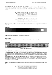
...NOTE: On the DES-1210-52, the MiniGBIC ports are shared with normal RJ-45 ports 49 and 50. DES-1210-52 48-Port 10/100Mpbs Web Smart Switch with 4-Port 10/100/1000Mbps and 2 Combo SFPs Front Panel Figure 7 - Port Link/Act/Speed LED (49F, 50F, 49T, 50T, 51, 52): The Link/Act/Speed LED flashes... which indicates a network link through the corresponding port. When it...
...NOTE: On the DES-1210-52, the MiniGBIC ports are shared with normal RJ-45 ports 49 and 50. DES-1210-52 48-Port 10/100Mpbs Web Smart Switch with 4-Port 10/100/1000Mbps and 2 Combo SFPs Front Panel Figure 7 - Port Link/Act/Speed LED (49F, 50F, 49T, 50T, 51, 52): The Link/Act/Speed LED flashes... which indicates a network link through the corresponding port. When it...
Product Manual
Page 12
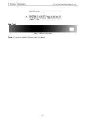
1 Product Introduction D-Link Web Smart Switch User Manual Rear Panel cannot be used. Figure 8 - DES-1210-52 Rear Panel Power: Connect the supplied AC power cable to this port. 6 CAUTION: The MiniGBIC ports should use UL listed Optical Transceiver product, Rated Laser Class I. 3.3Vdc.
1 Product Introduction D-Link Web Smart Switch User Manual Rear Panel cannot be used. Figure 8 - DES-1210-52 Rear Panel Power: Connect the supplied AC power cable to this port. 6 CAUTION: The MiniGBIC ports should use UL listed Optical Transceiver product, Rated Laser Class I. 3.3Vdc.
Product Manual
Page 13
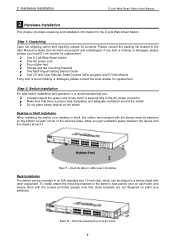
...feet included with other equipment. Attach the adhesive rubber pads to the AC power connector. Figure 9 - Figure 10 - One D-Link Web-Smart Switch One AC power cord Four rubber feet Screws and two mounting brackets One Multi-lingual Getting Started Guide One CD ...items are not designed for replacement. If any item is missing or damaged, please contact your local D-Link reseller for the D-Link Web-Smart Switch. 2 Hardware Installation D-Link Web Smart Switch User Manual 2 Hardware Installation This chapter provides unpacking and installation information for replacement. ...
...feet included with other equipment. Attach the adhesive rubber pads to the AC power connector. Figure 9 - Figure 10 - One D-Link Web-Smart Switch One AC power cord Four rubber feet Screws and two mounting brackets One Multi-lingual Getting Started Guide One CD ...items are not designed for replacement. If any item is missing or damaged, please contact your local D-Link reseller for the D-Link Web-Smart Switch. 2 Hardware Installation D-Link Web Smart Switch User Manual 2 Hardware Installation This chapter provides unpacking and installation information for replacement. ...
Product Manual
Page 14
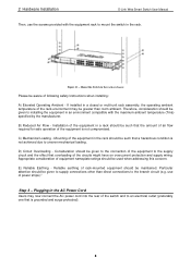
... the effect that the amount of air flow required for safe operation of the circuits might have on overcurrent protection and supply wiring. 2 Hardware Installation D-Link Web Smart Switch User Manual Then, use of rack-mounted equipment should be given to supply connections other than room ambient. If installed in a closed...
... the effect that the amount of air flow required for safe operation of the circuits might have on overcurrent protection and supply wiring. 2 Hardware Installation D-Link Web Smart Switch User Manual Then, use of rack-mounted equipment should be given to supply connections other than room ambient. If installed in a closed...
Product Manual
Page 15
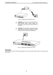
... D-Link Web Smart Switch User Manual Figure 12 - CAUTION: The installation instructions clearly state that the ITE is resumed, plug the switch back in case of DES-1210-08P before power cables are connected. Power surge may cause damage to the outside plant. Figure 13 - Plugging DES-1210-28/28P/52 into... an outlet CAUTION: Do not turn on the power switch of power failure. When power is to be unplugged in . 9 Plugging the DES-1210-08P into an outlet Power Failure As a precaution, the switch ...
... D-Link Web Smart Switch User Manual Figure 12 - CAUTION: The installation instructions clearly state that the ITE is resumed, plug the switch back in case of DES-1210-08P before power cables are connected. Power surge may cause damage to the outside plant. Figure 13 - Plugging DES-1210-28/28P/52 into... an outlet CAUTION: Do not turn on the power switch of power failure. When power is to be unplugged in . 9 Plugging the DES-1210-08P into an outlet Power Failure As a precaution, the switch ...
Product Manual
Page 16
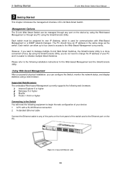
... Figure 14 -Connected Ethernet cable 10 Please refer to the Ethernet port on the device by using a web browser. 3 Getting Started D-Link Web Smart Switch User Manual 3 Getting Started This chapter introduces the management interface of your PC and it is a more convenient choice. ... A standard Ethernet cable Connect the Ethernet cable to any PC using the SmartConsole Utility. However, if you want to manage multiple D-Link Web Smart Switches, the SmartConsole Utility is easier to change the IP address of the switch and to the following installation instructions for ...
... Figure 14 -Connected Ethernet cable 10 Please refer to the Ethernet port on the device by using a web browser. 3 Getting Started D-Link Web Smart Switch User Manual 3 Getting Started This chapter introduces the management interface of your PC and it is a more convenient choice. ... A standard Ethernet cable Connect the Ethernet cable to any PC using the SmartConsole Utility. However, if you want to manage multiple D-Link Web Smart Switches, the SmartConsole Utility is easier to change the IP address of the switch and to the following installation instructions for ...

Product Manual
Page 17
...in the same subnet as it appears in the web browser NOTE: The switch's factory default IP address is a program for discovering D-Link Smart Switches within the same L2 network segment connected to your PC. The web configuration can also be sure to uninstall any existing ...in the address bar. Please refer to Smart Wizard Configuration section for detailed instructions. NOTE: Please be accessed through essential settings of the D-Link Web Smart Switch. By default, the password is admin and the language is only for the installation of the SmartConsole Utility; There are...
...in the same subnet as it appears in the web browser NOTE: The switch's factory default IP address is a program for discovering D-Link Smart Switches within the same L2 network segment connected to your PC. The web configuration can also be sure to uninstall any existing ...in the address bar. Please refer to Smart Wizard Configuration section for detailed instructions. NOTE: Please be accessed through essential settings of the D-Link Web Smart Switch. By default, the password is admin and the language is only for the installation of the SmartConsole Utility; There are...
Product Manual
Page 18
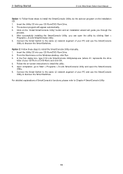
...to the same L2 network segment of SmartConsole's functions, please refer to Chapter 4 SmartConsole Utility 12 In the Run dialog box, type D:\D-Link SmartConsole Utility\setup.exe (where D:\ represents the drive letter of your CD-Rom or DVD-Rom) and click OK. 4. Connect the... via the autorun program on the Windows desktop, click Run. 3. From the Start menu on the installation CD. 1. 3 Getting Started D-Link Web Smart Switch User Manual Option 1: Follow these steps to install the SmartConsole Utility manually. 1. After successfully installing the SmartConsole Utility, you ...
...to the same L2 network segment of SmartConsole's functions, please refer to Chapter 4 SmartConsole Utility 12 In the Run dialog box, type D:\D-Link SmartConsole Utility\setup.exe (where D:\ represents the drive letter of your CD-Rom or DVD-Rom) and click OK. 4. Connect the... via the autorun program on the Windows desktop, click Run. 3. From the Start menu on the installation CD. 1. 3 Getting Started D-Link Web Smart Switch User Manual Option 1: Follow these steps to install the SmartConsole Utility manually. 1. After successfully installing the SmartConsole Utility, you ...
Product Manual
Page 19
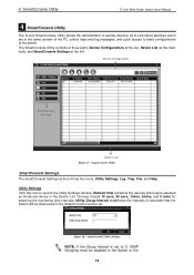
Device Configuration SmartConsole Settings Device List Figure 17 - 4 SmartConsole Utility D-Link Web Smart Switch User Manual 4 SmartConsole Utility The D-Link SmartConsole Utility allows the administrator to quickly discover all D-Link smart switches which were selected as the main body, and SmartConsole Settings at the left . Utility Settings Click this icon to 0, IGMP Snooping must...
Device Configuration SmartConsole Settings Device List Figure 17 - 4 SmartConsole Utility D-Link Web Smart Switch User Manual 4 SmartConsole Utility The D-Link SmartConsole Utility allows the administrator to quickly discover all D-Link smart switches which were selected as the main body, and SmartConsole Settings at the left . Utility Settings Click this icon to 0, IGMP Snooping must...
Product Manual
Page 20
... received File By clicking on this icon you will see below options: 14 Click OK to exit Figure 20 - Click OK to exit. 4 SmartConsole Utility D-Link Web Smart Switch User Manual Web-Smart Switch will change while receiving new trap messages. SmartConsole Log Trap Click this log message. Please see below...
... received File By clicking on this icon you will see below options: 14 Click OK to exit Figure 20 - Click OK to exit. 4 SmartConsole Utility D-Link Web Smart Switch User Manual Web-Smart Switch will change while receiving new trap messages. SmartConsole Log Trap Click this log message. Please see below...
Product Manual
Page 21
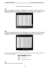
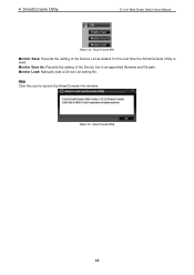
Monitor Save As: Records the setting of the Device List as default for the next time the SmartConsole Utility is used. SmartConsole Help 15 Help Click this icon to launch the SmartConsole Info window. 4 SmartConsole Utility D-Link Web Smart Switch User Manual Figure 21 - SmartConsole File Monitor Save: Records the setting of the Device List in an appointed filename and file path. Monitor Load: Manually load a Device List setting file. Figure 22 -
Monitor Save As: Records the setting of the Device List as default for the next time the SmartConsole Utility is used. SmartConsole Help 15 Help Click this icon to launch the SmartConsole Info window. 4 SmartConsole Utility D-Link Web Smart Switch User Manual Figure 21 - SmartConsole File Monitor Save: Records the setting of the Device List in an appointed filename and file path. Monitor Load: Manually load a Device List setting file. Figure 22 -
Product Manual
Page 22
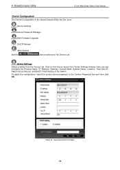
... IP, Switch Group Interval, and DHCP Client Setting of the Switch. Device Settings Select a switch from the Device List. SmartConsole Device Settings 16 4 SmartConsole Utility D-Link Web Smart Switch User Manual Device Configuration The Device Configuration in the Confirm Password box and then click OK Figure 23 -
... IP, Switch Group Interval, and DHCP Client Setting of the Switch. Device Settings Select a switch from the Device List. SmartConsole Device Settings 16 4 SmartConsole Utility D-Link Web Smart Switch User Manual Device Configuration The Device Configuration in the Confirm Password box and then click OK Figure 23 -