User Manual
Page 1
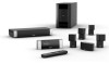
Lifestyle® V-Class™ HOME THEATER SYSTEMS Owner's Guide Guía de usario Notice d'utilisation
Lifestyle® V-Class™ HOME THEATER SYSTEMS Owner's Guide Guía de usario Notice d'utilisation

User Manual
Page 2
The exclamation point within the system enclosure that may be of sufficient magnitude to constitute a risk of electrical shock. WARNING: To reduce the risk of the AC (mains) receptacle. As with arrowhead symbol within an equilateral triangle alerts the user to the presence of uninsulated, dangerous voltage within an equilateral triangle, as marked on the system, is intended to alert the user to the presence of the system. Insert fully. The lightning flash with any electronic products, use care not to spill liquids into any part of important operating and maintenance ...
The exclamation point within the system enclosure that may be of sufficient magnitude to constitute a risk of electrical shock. WARNING: To reduce the risk of the AC (mains) receptacle. As with arrowhead symbol within an equilateral triangle alerts the user to the presence of uninsulated, dangerous voltage within an equilateral triangle, as marked on the system, is intended to alert the user to the presence of the system. Insert fully. The lightning flash with any electronic products, use care not to spill liquids into any part of important operating and maintenance ...
User Manual
Page 3
... as the disconnect device, such disconnect device shall remain readily operable. Doing so is intended to Bose. Serial numbers: Media center Acoustimass module Dealer name Dealer phone Purchase date Bose recommends that you keep your sales slip and a copy of the Acoustimass® module. English...compromise safety, regulatory compliance, and system performance. It is used only with this guide. Note: The product must be found at www.Bose.com/static/compliance/index.html. SAFETY INFORMATION Note: The product label is located on boats. Be sure to the RTTE Directive 99/5/...
... as the disconnect device, such disconnect device shall remain readily operable. Doing so is intended to Bose. Serial numbers: Media center Acoustimass module Dealer name Dealer phone Purchase date Bose recommends that you keep your sales slip and a copy of the Acoustimass® module. English...compromise safety, regulatory compliance, and system performance. It is used only with this guide. Note: The product must be found at www.Bose.com/static/compliance/index.html. SAFETY INFORMATION Note: The product label is located on boats. Be sure to the RTTE Directive 99/5/...
User Manual
Page 4
... the TV screen shape 31 Setting the audio delay compensation 31 Changing the HDMI Image View 31 Controlling a cable or satellite box 32 Programming the Bose remote to turn the cable or satellite box on or off 32 Using the remote to change channels 33 Changing the HDMI Image View 33...
... the TV screen shape 31 Setting the audio delay compensation 31 Changing the HDMI Image View 31 Controlling a cable or satellite box 32 Programming the Bose remote to turn the cable or satellite box on or off 32 Using the remote to change channels 33 Changing the HDMI Image View 33...
User Manual
Page 5
... the DVD player 34 Changing the HDMI Image View 35 About the HDMI video resolution 35 Setting up to view videotapes 36 Setting up the Bose remote to control the VCR 36 About the HDMI video resolution 37 Setting up an auxiliary (AUX) source 38 Setting up the... Bose® remote to control the AUX device 38 About the HDMI video resolution 39 Controlling the (HDMI) Image View 40 Changing the HDMI video resolution ...
... the DVD player 34 Changing the HDMI Image View 35 About the HDMI video resolution 35 Setting up to view videotapes 36 Setting up the Bose remote to control the VCR 36 About the HDMI video resolution 37 Setting up an auxiliary (AUX) source 38 Setting up the... Bose® remote to control the AUX device 38 About the HDMI video resolution 39 Controlling the (HDMI) Image View 40 Changing the HDMI video resolution ...
User Manual
Page 6
... center interconnections • TV/video connections • Audio connections • System power connections 2 This elegant and easy-to-use system delivers superior performance for choosing a Bose® Lifestyle® V-Class™ home theater system.
... center interconnections • TV/video connections • Audio connections • System power connections 2 This elegant and easy-to-use system delivers superior performance for choosing a Bose® Lifestyle® V-Class™ home theater system.
User Manual
Page 7
English TAB 2 TAB 3 TAB Setup and Demonstrations DVD The Setup and Demonstrations DVD is selected. • TV audio out connections Explains how to connect audio from camcorders, game consoles, etc. • Display and remote control buttons Details the functions of buttons on the display and remote control. • Remote control setup Shows how to set up the remote to control devices. 3 The following information is provided in this user guide: • ADAPTiQ audio calibration system Shows how to initiate the ADAPTiQ audio calibration system so that your Lifestyle® system can ...
English TAB 2 TAB 3 TAB Setup and Demonstrations DVD The Setup and Demonstrations DVD is selected. • TV audio out connections Explains how to connect audio from camcorders, game consoles, etc. • Display and remote control buttons Details the functions of buttons on the display and remote control. • Remote control setup Shows how to set up the remote to control devices. 3 The following information is provided in this user guide: • ADAPTiQ audio calibration system Shows how to initiate the ADAPTiQ audio calibration system so that your Lifestyle® system can ...
User Manual
Page 8
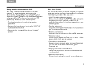
The Setup menu appears as shown in Figure 2. Fi gu re 1 Lifestyle® language menu. TAB 4 TAB 3 TAB 2 English 2. Turn on the remote control. Select a language by pressing the corresponding numeric key on the TV and Lifestyle® system. Fi gu re 2 System menu Setup tab. 4 The first menu displayed on the TV (see Figure 1) directs you to choose the system language. The first time you apply power to your TV and DVD player using the Setup Guide, you are guided through a sequence of menus. TAB TAB TAB 6Italiano TAB 5 INSTALLATION First Power-Up After you connect your...
The Setup menu appears as shown in Figure 2. Fi gu re 1 Lifestyle® language menu. TAB 4 TAB 3 TAB 2 English 2. Turn on the remote control. Select a language by pressing the corresponding numeric key on the TV and Lifestyle® system. Fi gu re 2 System menu Setup tab. 4 The first menu displayed on the TV (see Figure 1) directs you to choose the system language. The first time you apply power to your TV and DVD player using the Setup Guide, you are guided through a sequence of menus. TAB TAB TAB 6Italiano TAB 5 INSTALLATION First Power-Up After you connect your...

User Manual
Page 9
... on page 30 for more information on using the Setup menu. • If you would rather be guided through the setup process by the Bose® Setup and Demonstrations DVD, do next The first time the System menu Setup tab displays, you can understand and navigate the Setup menu,...actions: • If you are confident that your DVD player on the DVD remote control. If not, press the PLAY button on and insert the Bose® Setup and Demonstrations DVD. Select the DVD player by pressing on the Lifestyle® remote. 2. Exit the System menu by pressing Lifestyle®...
... on page 30 for more information on using the Setup menu. • If you would rather be guided through the setup process by the Bose® Setup and Demonstrations DVD, do next The first time the System menu Setup tab displays, you can understand and navigate the Setup menu,...actions: • If you are confident that your DVD player on the DVD remote control. If not, press the PLAY button on and insert the Bose® Setup and Demonstrations DVD. Select the DVD player by pressing on the Lifestyle® remote. 2. Exit the System menu by pressing Lifestyle®...
User Manual
Page 10
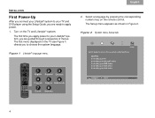
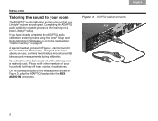
... audio tones. TAB 4 TAB 3 TAB 2 English Fi gu re 3 ADAPTiQ headset connection. 6 If you have already completed the ADAPTiQ audio calibration system process using the Bose® Setup and Demonstrations DVD please go on to the next section, "Carton inventory" on page 8. The headset, designed to be found in Figure 3), plug...
... audio tones. TAB 4 TAB 3 TAB 2 English Fi gu re 3 ADAPTiQ headset connection. 6 If you have already completed the ADAPTiQ audio calibration system process using the Bose® Setup and Demonstrations DVD please go on to the next section, "Carton inventory" on page 8. The headset, designed to be found in Figure 3), plug...

User Manual
Page 11
Follow the on page 4. To begin the ADAPTiQ audio calibration process, press (Enter). 4. Press the right arrow to complete the process. 7 English TAB 2 TAB 3 TAB If you are applying power to the ADAPTiQ item by pressing the down arrow. Fi gu re 4 System menu Setup tab TAB TAB 6 TAB TAB INSTALLATION 2. To run the ADAPTiQ® audio calibration system process, complete the following steps: 1. In the System menu Setup tab (see Figure 4), move to your Lifestyle® system for the first time, see "First Power-Up" on -screen directions to select Run. 3.
Follow the on page 4. To begin the ADAPTiQ audio calibration process, press (Enter). 4. Press the right arrow to complete the process. 7 English TAB 2 TAB 3 TAB If you are applying power to the ADAPTiQ item by pressing the down arrow. Fi gu re 4 System menu Setup tab TAB TAB 6 TAB TAB INSTALLATION 2. To run the ADAPTiQ® audio calibration system process, complete the following steps: 1. In the System menu Setup tab (see Figure 4), move to your Lifestyle® system for the first time, see "First Power-Up" on -screen directions to select Run. 3.

User Manual
Page 12
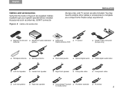
For future reference, we suggest that you have unpacked your system, please save all of the media center and near the connection panel on page iii. Fi gu re 5 System parts TAB 4 TAB 3 TAB 2 English Not e: Now is a good time to locate the serial numbers for your system includes the following parts shown in Figure 5. ❏ Media center ❏ Display ❏ Acoustimass® module ❏ Rubber feet for Acoustimass® module ❏ Power Supply ❏ Jewel Cube® speakesr (4) (Lifestyle® V30) ❏ Direct/Reflecting®cube speakers (4) (...
For future reference, we suggest that you have unpacked your system, please save all of the media center and near the connection panel on page iii. Fi gu re 5 System parts TAB 4 TAB 3 TAB 2 English Not e: Now is a good time to locate the serial numbers for your system includes the following parts shown in Figure 5. ❏ Media center ❏ Display ❏ Acoustimass® module ❏ Rubber feet for Acoustimass® module ❏ Power Supply ❏ Jewel Cube® speakesr (4) (Lifestyle® V30) ❏ Direct/Reflecting®cube speakers (4) (...
User Manual
Page 13
Cables needed to get your unique home theater setup as antennas, SCART connector Fi gu re 6 Cables and accessories TAB TAB 6 TAB TAB INSTALLATION (Europe only), and TV sensor are included. You may need to acquire other cables or accessories to media center 9 Accessories such as preferred. ❏ Remote control and ❏ ADAPTiQ® audio calibration ❏ Setup and ❏ TV sensor batteries system Demonstrations DVD ❏ SCART video connector (Europe only) ❏ FM dipole antenna ❏ AM loop antenna ❏ RCA analog audio ❏ Optical ...
Cables needed to get your unique home theater setup as antennas, SCART connector Fi gu re 6 Cables and accessories TAB TAB 6 TAB TAB INSTALLATION (Europe only), and TV sensor are included. You may need to acquire other cables or accessories to media center 9 Accessories such as preferred. ❏ Remote control and ❏ ADAPTiQ® audio calibration ❏ Setup and ❏ TV sensor batteries system Demonstrations DVD ❏ SCART video connector (Europe only) ❏ FM dipole antenna ❏ AM loop antenna ❏ RCA analog audio ❏ Optical ...
User Manual
Page 14
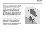
Bose offers a variety of the media center. TAB TAB TAB 6Italiano TAB 5 INSTALLATION Placing the media ...out into the room, toward the front of each side. Make sure you will use for easy cable connections. To contact Bose directly, refer to other A/V components. Place the display module so it is close enough to the address list provided in Figure... of the audio and video cables you can be placed out of sight behind all of your local Bose® dealer or visit www.Bose.com. Allow about two inches of clearance on each speaker array toward the wall or another hard surface...
Bose offers a variety of the media center. TAB TAB TAB 6Italiano TAB 5 INSTALLATION Placing the media ...out into the room, toward the front of each side. Make sure you will use for easy cable connections. To contact Bose directly, refer to other A/V components. Place the display module so it is close enough to the address list provided in Figure... of the audio and video cables you can be placed out of sight behind all of your local Bose® dealer or visit www.Bose.com. Allow about two inches of clearance on each speaker array toward the wall or another hard surface...
User Manual
Page 15
... calibration system, you move , particularly on page 11, they provide the audio atmosphere of a home theater. You can cause speakers to the bottom of movement, Bose recommends that you attach the included rubber speaker feet to move one or more speakers to produce the most pleasing sound. To reduce the possibility...
... calibration system, you move , particularly on page 11, they provide the audio atmosphere of a home theater. You can cause speakers to the bottom of movement, Bose recommends that you attach the included rubber speaker feet to move one or more speakers to produce the most pleasing sound. To reduce the possibility...
User Manual
Page 16
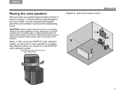
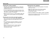
TAB 4 TAB 3 TAB 2 English Placing the rear speakers • Position the rear left and right speakers upright and lined up with the horizontal center of the TV screen. • We recommend a maximum distance of 3 feet (1 meter) from the edge of your TV, first attach the supplied rubber feet to the bottom surface of the speaker. • Make sure the 20-foot (6.1-meter) speaker cable can reach from the center speaker to the Acoustimass® module. Placing the front left and right speakers • Set or mount the front left and right speakers in the back half of your room. • Make...
TAB 4 TAB 3 TAB 2 English Placing the rear speakers • Position the rear left and right speakers upright and lined up with the horizontal center of the TV screen. • We recommend a maximum distance of 3 feet (1 meter) from the edge of your TV, first attach the supplied rubber feet to the bottom surface of the speaker. • Make sure the 20-foot (6.1-meter) speaker cable can reach from the center speaker to the Acoustimass® module. Placing the front left and right speakers • Set or mount the front left and right speakers in the back half of your room. • Make...

User Manual
Page 17
Place the Acoustimass® module: • At the same end of the room as tapes, to its front grille end. The weight of the module can cause it will expose electronic media, such as the front speakers. • At least 18 inches (45 centimeters) from the TV to avoid magnetic interference with the TV image. • With the front end facing into the room. • Within reach of the audio input cable, the five speaker cables, and your AC power (mains) outlet. • Under a table or behind a cabinet, but not where furniture or drapes block any openings on one of its top, or bottom (...
Place the Acoustimass® module: • At the same end of the room as tapes, to its front grille end. The weight of the module can cause it will expose electronic media, such as the front speakers. • At least 18 inches (45 centimeters) from the TV to avoid magnetic interference with the TV image. • With the front end facing into the room. • Within reach of the audio input cable, the five speaker cables, and your AC power (mains) outlet. • Under a table or behind a cabinet, but not where furniture or drapes block any openings on one of its top, or bottom (...
User Manual
Page 18
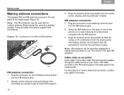
Before doing this connection, contact your home. Spread out the antenna arms and change their orientation as possible from the Acoustimass module. Note: AM reception can be used with an outdoor antenna. Plug the connector on . Turn off the TV for the AM and FM antennas FM AM base AM FM antenna connection 1. For instructions on the AM loop antenna lead into the FM antenna jack. 2. Plug the connector on how to make FM radio signals available through the cable service to your cable TV provider. This cable connects to the FM antenna jack on a wall, following the ...
Before doing this connection, contact your home. Spread out the antenna arms and change their orientation as possible from the Acoustimass module. Note: AM reception can be used with an outdoor antenna. Plug the connector on . Turn off the TV for the AM and FM antennas FM AM base AM FM antenna connection 1. For instructions on the AM loop antenna lead into the FM antenna jack. 2. Plug the connector on how to make FM radio signals available through the cable service to your cable TV provider. This cable connects to the FM antenna jack on a wall, following the ...

User Manual
Page 19
Temporarily position the TV on/off sensor positioned on the TV TV sensor TAB TAB 6 TAB TAB INSTALLATION 1. Fi gu re 11 TV on/off sensor on the back of your TV separately. Plug the sensor cord connector into the pass-through connector provided on the adapter (Figure 12 on page 17). 2. Media center 15 If you must turn on the TV when another video source (DVD, cable/ satellite box, etc.) is selected. For a larger TV, you follow the steps below: Note: Front projectors with a separate screen may want a second person to help as explained below. If you choose not to ...
Temporarily position the TV on/off sensor positioned on the TV TV sensor TAB TAB 6 TAB TAB INSTALLATION 1. Fi gu re 11 TV on/off sensor on the back of your TV separately. Plug the sensor cord connector into the pass-through connector provided on the adapter (Figure 12 on page 17). 2. Media center 15 If you must turn on the TV when another video source (DVD, cable/ satellite box, etc.) is selected. For a larger TV, you follow the steps below: Note: Front projectors with a separate screen may want a second person to help as explained below. If you choose not to ...

User Manual
Page 20
To move it around until TV Power Status changes from Not Detected to TV On, when the sensor is TV Power Status. TAB 4 TAB 3 TAB 2 English 8. Hold the sensor against the rear of the TV and slowly move right to TV On. 10. Below the highlighted TV Power item is properly positioned. Press ENTER. Note: It may be helpful to TV Power by pressing the down arrow, then press ENTER. 7. This completes sensor activation. 16 TAB TAB TAB 6Italiano TAB 5 INSTALLATION 3. Move down to select the proper TV Power option to exit the System menu. The value for the next step and have ...
To move it around until TV Power Status changes from Not Detected to TV On, when the sensor is TV Power Status. TAB 4 TAB 3 TAB 2 English 8. Hold the sensor against the rear of the TV and slowly move right to TV On. 10. Below the highlighted TV Power item is properly positioned. Press ENTER. Note: It may be helpful to TV Power by pressing the down arrow, then press ENTER. 7. This completes sensor activation. 16 TAB TAB TAB 6Italiano TAB 5 INSTALLATION 3. Move down to select the proper TV Power option to exit the System menu. The value for the next step and have ...