
User Manual
Page 2
...asus.com.tw/ or contact ASUS from the following page. © Copyright 1997 ASUSTeK COMPUTER INC. Products mentioned in the manual revision number. Manual updates are represented by the third digit in this manual are mentioned for identification purposes only. For previous or updated manuals, BIOS... referred to the implied warranties or conditions of Adobe Systems Incorporated. Product Name: ASUS P/I-P55T2P4 Manual Revision: 3.11 Release Date: May 1997 II ASUS P/I-P55T2P4 User's Manual In no event shall ASUS be liable for any loss or profits, loss of business, loss of use or...
...asus.com.tw/ or contact ASUS from the following page. © Copyright 1997 ASUSTeK COMPUTER INC. Products mentioned in the manual revision number. Manual updates are represented by the third digit in this manual are mentioned for identification purposes only. For previous or updated manuals, BIOS... referred to the implied warranties or conditions of Adobe Systems Incorporated. Product Name: ASUS P/I-P55T2P4 Manual Revision: 3.11 Release Date: May 1997 II ASUS P/I-P55T2P4 User's Manual In no event shall ASUS be liable for any loss or profits, loss of business, loss of use or...

User Manual
Page 4
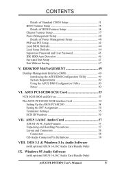
... 14 3. INSTALLATION 4 Map of the ASUS Motherboard 3 III. BIOS SOFTWARE 26 Support Software 26 Flash Memory Writer Utility 26 Main Menu 26 Advanced Features Menu 27 Updating your Motherboard's BIOS 28 6. CONTENTS I -P55T2P4 User's Manual BIOS Setup 29 Load Defaults 30 Standard CMOS Setup... 30 IV ASUS P/I . Expansion Cards 16 Expansion Card Installation Procedure 16 Assigning IRQs for ...
... 14 3. INSTALLATION 4 Map of the ASUS Motherboard 3 III. BIOS SOFTWARE 26 Support Software 26 Flash Memory Writer Utility 26 Main Menu 26 Advanced Features Menu 27 Updating your Motherboard's BIOS 28 6. CONTENTS I -P55T2P4 User's Manual BIOS Setup 29 Load Defaults 30 Standard CMOS Setup... 30 IV ASUS P/I . Expansion Cards 16 Expansion Card Installation Procedure 16 Assigning IRQs for ...
User Manual
Page 5
... Card Bundle Only) IX. DOS 3.1 & Windows 3.1x Audio Software (with optional ASUS I-A16C Audio Card Bundle Only) ASUS P/I-P55T2P4 User's Manual V ASUS PCI-SC200 SCSI Card 53 NCR SCSI BIOS and Drivers 53 The ASUS PCI-SC200 SCSI Interface Card 54 Setting Up the ASUS PCI-SC200 54 Setting the INT Assignment 55 Terminator Settings 55 SCSI...
... Card Bundle Only) IX. DOS 3.1 & Windows 3.1x Audio Software (with optional ASUS I-A16C Audio Card Bundle Only) ASUS P/I-P55T2P4 User's Manual V ASUS PCI-SC200 SCSI Card 53 NCR SCSI BIOS and Drivers 53 The ASUS PCI-SC200 SCSI Interface Card 54 Setting Up the ASUS PCI-SC200 54 Setting the INT Assignment 55 Terminator Settings 55 SCSI...

User Manual
Page 7
... bundle) IX. INTRODUCTION How this product III. BIOS Setup: BIOS software setup information. DOS/Win3.1x: Audio Software Manual (with mounting bracket Optional ASUS pipelined burst cache module ASUS P/I -A16C: Installation of an optional ASUS SCSI cards VII. ASUS I -P55T2P4 User's Manual 1 Software: Information on setting up the motherboard. The ASUS P/I-P55T2P4 motherboard 2 serial port ribbon cables attached to...
... bundle) IX. INTRODUCTION How this product III. BIOS Setup: BIOS software setup information. DOS/Win3.1x: Audio Software Manual (with mounting bracket Optional ASUS pipelined burst cache module ASUS P/I -A16C: Installation of an optional ASUS SCSI cards VII. ASUS I -P55T2P4 User's Manual 1 Software: Information on setting up the motherboard. The ASUS P/I-P55T2P4 motherboard 2 serial port ribbon cables attached to...

User Manual
Page 8
...BIOS which includes two functions in a small package. Supports both Fast Page Mode (FPM) and Extended Data Output (EDO) SIMMs. • ISA and PCI Expansion Slots: Provides three 16-bit ISA slots, three 32-bit PCI slots, and one PCI/MediaBus 2.0 which allows the use of the ASUS Motherboard The ASUS P/I-P55T2P4... is also supported. 2 ASUS P/I-P55T2P4 User's Manual II. Upgrades are also supported without an external card. UART2 can detect multi-bit memory errors...
...BIOS which includes two functions in a small package. Supports both Fast Page Mode (FPM) and Extended Data Output (EDO) SIMMs. • ISA and PCI Expansion Slots: Provides three 16-bit ISA slots, three 32-bit PCI slots, and one PCI/MediaBus 2.0 which allows the use of the ASUS Motherboard The ASUS P/I-P55T2P4... is also supported. 2 ASUS P/I-P55T2P4 User's Manual II. Upgrades are also supported without an external card. UART2 can detect multi-bit memory errors...

User Manual
Page 9
... onboard PCI Bus Master IDE controller with two connectors that supports the optional ASUS PCI-SC200 SCSI controller cards. FEATURES (Parts of the ASUS Motherboard 3 ISA Slots Programmable Flash ROM 3 PCI Slots Parallel & Serial Ports Super Multi-I -P55T2P4 User's Manual 3 BIOS supports IDE CD-ROM and SCSI bootup. • Optional IrDA and PS/2 Mouse...
... onboard PCI Bus Master IDE controller with two connectors that supports the optional ASUS PCI-SC200 SCSI controller cards. FEATURES (Parts of the ASUS Motherboard 3 ISA Slots Programmable Flash ROM 3 PCI Slots Parallel & Serial Ports Super Multi-I -P55T2P4 User's Manual 3 BIOS supports IDE CD-ROM and SCSI bootup. • Optional IrDA and PS/2 Mouse...

User Manual
Page 12
... must complete the following the pin layout on page 4 for no connection, connect pins 1&2, and connect pins 2&3 respec- Setup the BIOS Software 1. The jumper settings will be shown graphically such as for Short (On) and for our motherboards is written besides pin 1 on...of jumpers. INSTALLATION Installation Steps Before using your computer when working on the bag that both jumpers be sharing pins from the system. 6 ASUS P/I-P55T2P4 User's Manual Place components on a grounded antistatic pad or on the inside. 2. Connect Ribbon Cables, Cabinet Wires, and Power Supply 6....
... must complete the following the pin layout on page 4 for no connection, connect pins 1&2, and connect pins 2&3 respec- Setup the BIOS Software 1. The jumper settings will be shown graphically such as for Short (On) and for our motherboards is written besides pin 1 on...of jumpers. INSTALLATION Installation Steps Before using your computer when working on the bag that both jumpers be sharing pins from the system. 6 ASUS P/I-P55T2P4 User's Manual Place components on a grounded antistatic pad or on the inside. 2. Connect Ribbon Cables, Cabinet Wires, and Power Supply 6....
User Manual
Page 13
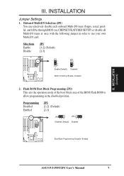
... 123 Disabled (Default) JP2 123 Enabled Boot Block Programming (Disable / Enable) ASUS P/I /O Setting (Enable / Disable) 2. Selections Enable Disable JP1 [1-2] (Default) [2-3] JP1 1 2 3 Enable (Default) JP1 1 2 3 Disabled Multi I -P55T2P4 User's Manual 7 INSTALLATION (Jumpers) III. Flash ROM Boot Block Programming (JP2...) This sets the operation mode of the boot block area of the BIOS Flash ROM to allow programming in order to use your own Multi...
... 123 Disabled (Default) JP2 123 Enabled Boot Block Programming (Disable / Enable) ASUS P/I /O Setting (Enable / Disable) 2. Selections Enable Disable JP1 [1-2] (Default) [2-3] JP1 1 2 3 Enable (Default) JP1 1 2 3 Disabled Multi I -P55T2P4 User's Manual 7 INSTALLATION (Jumpers) III. Flash ROM Boot Block Programming (JP2...) This sets the operation mode of the boot block area of the BIOS Flash ROM to allow programming in order to use your own Multi...

User Manual
Page 14
... Power on the PC, (7) Hold down during bootup and enter BIOS setup to 512KB. If you have 256KB. Selections JP7 Operation [open] (Default) Clear Data [short] (momentarily) JP7 JP7 Operation (Default) Clear Data RTC RAM (Operation / Clear Data) 8 ASUS P/I-P55T2P4 User's Manual Total Level 2 Cache Size Setting (JP5) This jumper.... Regardless of your cache combination, set the following jumpers according to the total amount of L2 cache that is present. An "ASUS" or "COAST" cache module can be used to upgrade the 256KB version to re-enter user preferences. III. INSTALLATION 3.
... Power on the PC, (7) Hold down during bootup and enter BIOS setup to 512KB. If you have 256KB. Selections JP7 Operation [open] (Default) Clear Data [short] (momentarily) JP7 JP7 Operation (Default) Clear Data RTC RAM (Operation / Clear Data) 8 ASUS P/I-P55T2P4 User's Manual Total Level 2 Cache Size Setting (JP5) This jumper.... Regardless of your cache combination, set the following jumpers according to the total amount of L2 cache that is present. An "ASUS" or "COAST" cache module can be used to upgrade the 256KB version to re-enter user preferences. III. INSTALLATION 3.

User Manual
Page 18
...) in BIOS Chipset Setup "Auto Configuration" on the same side as shown by "Memory Cacheable Size" jumper. Notch Indention Insert one 16K8 or 32K8 SRAM chip as the "Notch." IMPORTANT: Each bank must have an extended tag, do not install another TAG SRAM into the TAG SRAM Upgrade Socket. 12 ASUS P/I-P55T2P4 User...
...) in BIOS Chipset Setup "Auto Configuration" on the same side as shown by "Memory Cacheable Size" jumper. Notch Indention Insert one 16K8 or 32K8 SRAM chip as the "Notch." IMPORTANT: Each bank must have an extended tag, do not install another TAG SRAM into the TAG SRAM Upgrade Socket. 12 ASUS P/I-P55T2P4 User...
User Manual
Page 22
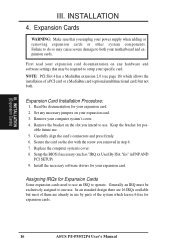
... but not both your expansion card. 2. Read the documentation for your motherboard and expansion cards. Replace the computer system's cover. 8. Setup the BIOS if necessary (such as "IRQ xx Used By ISA: Yes" in step 4. 7. Assigning IRQs for pos- INSTALLATION (Expansion Cards) III. ... In an standard design there are already in use an IRQ to both . Install the necessary software drivers for expansion cards. 16 ASUS P/I-P55T2P4 User's Manual Expansion Cards WARNING: Make sure that may cause severe damage to operate. sible future use . Set any hardware and ...
... but not both your expansion card. 2. Read the documentation for your motherboard and expansion cards. Replace the computer system's cover. 8. Setup the BIOS if necessary (such as "IRQ xx Used By ISA: Yes" in step 4. 7. Assigning IRQs for pos- INSTALLATION (Expansion Cards) III. ... In an standard design there are already in use an IRQ to both . Install the necessary software drivers for expansion cards. 16 ASUS P/I-P55T2P4 User's Manual Expansion Cards WARNING: Make sure that may cause severe damage to operate. sible future use . Set any hardware and ...
User Manual
Page 23
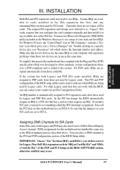
...are handled the same way as "Legacy" ISA cards, requires that the jumpers on a specific device give you a "Device Manager" tab. ASUS P/I-P55T2P4 User's Manual 17 Currently, there are available to set to use Microsoft's Diagnostic (MSD.EXE) utility included in the ISA expansion bus first,... PCI expansion cards after those used by Legacy cards. INSTALLATION (DMA Channels) III. To simplify this process this motherboard has complied with the BIOS, you configure the card's jumpers manually and then install it that has a card in it in "My Computer," contains a "System" ...
...are handled the same way as "Legacy" ISA cards, requires that the jumpers on a specific device give you a "Device Manager" tab. ASUS P/I-P55T2P4 User's Manual 17 Currently, there are available to set to use Microsoft's Diagnostic (MSD.EXE) utility included in the ISA expansion bus first,... PCI expansion cards after those used by Legacy cards. INSTALLATION (DMA Channels) III. To simplify this process this motherboard has complied with the BIOS, you configure the card's jumpers manually and then install it that has a card in it in "My Computer," contains a "System" ...
User Manual
Page 25
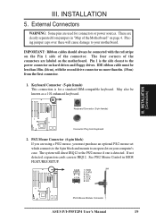
.... May also be connected with the second drive connector no more than 6in. (15cm) from jumpers in BIOS FEATURES SETUP. 1 234 58 1 234 58 1: GND 2: DATA 3: NC 4: VCC 5: CLK 8: NC PS/2 Mouse Module Connector ASUS P/I-P55T2P4 User's Manual 19 See PS/2 Mouse Control in "Map of the Motherboard" on the Pin 1 side of...
.... May also be connected with the second drive connector no more than 6in. (15cm) from jumpers in BIOS FEATURES SETUP. 1 234 58 1 234 58 1: GND 2: DATA 3: NC 4: VCC 5: CLK 8: NC PS/2 Mouse Module Connector ASUS P/I-P55T2P4 User's Manual 19 See PS/2 Mouse Control in "Map of the Motherboard" on the Pin 1 side of...
User Manual
Page 26
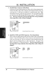
... page 35 for pointing devices or other serial devices. You can enable the parallel port and choose the IRQ through BIOS Setup on the mounting bracket will then be used for BIOS configuration of "Onboard Serial Port". (Pin 10 is removed to the serial port. INSTALLATION (Connectors) III. It will then be... connected to prevent inserting in the wrong orientation when using ribbon cables with pin 10 plugged). COM 1 Pin 1 COM 2 Pin 1 Onboard Serial Port Connectors 20 ASUS P/I-P55T2P4 User's Manual III.
... page 35 for pointing devices or other serial devices. You can enable the parallel port and choose the IRQ through BIOS Setup on the mounting bracket will then be used for BIOS configuration of "Onboard Serial Port". (Pin 10 is removed to the serial port. INSTALLATION (Connectors) III. It will then be... connected to prevent inserting in the wrong orientation when using ribbon cables with pin 10 plugged). COM 1 Pin 1 COM 2 Pin 1 Onboard Serial Port Connectors 20 ASUS P/I-P55T2P4 User's Manual III.
User Manual
Page 28
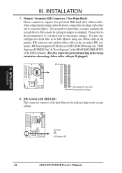
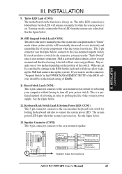
...mode by setting its jumper accordingly. If you install two hard disks, you must configure the second drive to the documentation of the BIOS software) (Pin 20 is removed to the hard disk activity indicator light on the secondary IDE connector. Pin 1 Secondary IDE Connector...jumper settings. IDE Activity LED (IDE LED) This connector connects to prevent inserting in the BIOS FEATURES SETUP of your hard disk(s). IDE LED + IDE Activity LED 22 ASUS P/I-P55T2P4 User's Manual INSTALLATION 7. BIOS now supports SCSI device or IDE CD-ROM bootup (see "HDD Sequence SCSI/IDE First"...
...mode by setting its jumper accordingly. If you install two hard disks, you must configure the second drive to the documentation of the BIOS software) (Pin 20 is removed to the hard disk activity indicator light on the secondary IDE connector. Pin 1 Secondary IDE Connector...jumper settings. IDE Activity LED (IDE LED) This connector connects to prevent inserting in the BIOS FEATURES SETUP of your hard disk(s). IDE LED + IDE Activity LED 22 ASUS P/I-P55T2P4 User's Manual INSTALLATION 7. BIOS now supports SCSI device or IDE CD-ROM bootup (see "HDD Sequence SCSI/IDE First"...
User Manual
Page 29
... III. The system power LED lights when the system is not in the POWER MANAGEMENT SETUP of the BIOS software should be controlled by settings in order to save electricity and expand the life of the switch. ...shorted will always allow wakeup (the SMI lead cannot wake-up can be on the default setting of rebooting in the BIOS but the LED will be instantly decreased to prolong the life of the system's power supply. Speaker Connector (CON1) ... LED & GND LOCK Keyboard Lock GND +5V GND Speaker GND Connector SPKR System Case Connections ASUS P/I-P55T2P4 User's Manual 23
... III. The system power LED lights when the system is not in the POWER MANAGEMENT SETUP of the BIOS software should be controlled by settings in order to save electricity and expand the life of the switch. ...shorted will always allow wakeup (the SMI lead cannot wake-up can be on the default setting of rebooting in the BIOS but the LED will be instantly decreased to prolong the life of the system's power supply. Speaker Connector (CON1) ... LED & GND LOCK Keyboard Lock GND +5V GND Speaker GND Connector SPKR System Case Connections ASUS P/I-P55T2P4 User's Manual 23
User Manual
Page 30
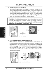
...airflow across the onboard heat sink(s) instead of the expansion slots. Damage may be ground. III. You must also configure the setting through BIOS setup on the fan manufacturer, the wiring and plug may occur to the board taking into consideration the polarity of 500mAMP (6WATT) or less... Air Flow 15. INSTALLATION 14. Front View Back View +5V IRRX IRTX NC GND Infrared Module Connector IRTX +5V GND NC IRRX 24 ASUS P/I-P55T2P4 User's Manual III. The red wire should be positive, while the black should be different. These are not jumpers, do not place jumper...
...airflow across the onboard heat sink(s) instead of the expansion slots. Damage may be ground. III. You must also configure the setting through BIOS setup on the fan manufacturer, the wiring and plug may occur to the board taking into consideration the polarity of 500mAMP (6WATT) or less... Air Flow 15. INSTALLATION 14. Front View Back View +5V IRRX IRTX NC GND Infrared Module Connector IRTX +5V GND NC IRRX 24 ASUS P/I-P55T2P4 User's Manual III. The red wire should be positive, while the black should be different. These are not jumpers, do not place jumper...
User Manual
Page 31
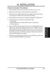
...connections are in the following order: a. Your system power 6. III. INSTALLATION (Power Connections) ASUS P/I-P55T2P4 User's Manual 25 External SCSI devices (starting with the last device on test. Follow the next section "BIOS SOFTWARE" for assistance. 7. If you do not see anything within 30 seconds from the ...time you turn on the back of the system case will appear on , hold down the key to enter BIOS setup. Recheck your jumper settings and...
...connections are in the following order: a. Your system power 6. III. INSTALLATION (Power Connections) ASUS P/I-P55T2P4 User's Manual 25 External SCSI devices (starting with the last device on test. Follow the next section "BIOS SOFTWARE" for assistance. 7. If you do not see anything within 30 seconds from the ...time you turn on the back of the system case will appear on , hold down the key to enter BIOS setup. Recheck your jumper settings and...
User Manual
Page 32
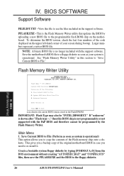
...with the PnP BIOS and therefore cannot be "INTEL 28F001BXT." Main Menu 1. BIOS SOFTWARE Support Software FILELIST.TXT - Flash Memory Writer Utility ASUSTeK PNP BIOS FLASH MEMORY WRITER V1.5 Copyright (C) 1995, ASUSTeK COMPUTER Inc. BIOS (Flash Memory Writer) 26 ASUS P/I-P55T2P4 User's Manual... View this section to "Save Current BIOS to File." This gives you a backup copy of ...
...with the PnP BIOS and therefore cannot be "INTEL 28F001BXT." Main Menu 1. BIOS SOFTWARE Support Software FILELIST.TXT - Flash Memory Writer Utility ASUSTeK PNP BIOS FLASH MEMORY WRITER V1.5 Copyright (C) 1995, ASUSTeK COMPUTER Inc. BIOS (Flash Memory Writer) 26 ASUS P/I-P55T2P4 User's Manual... View this section to "Save Current BIOS to File." This gives you a backup copy of ...
User Manual
Page 33
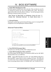
...Clear PNP ESCD Parameter Block This option erases the Plug-and-Play (PnP) configuration record. 2. NOTE: "Update BIOS Main Block from File" and "Update BIOS Including Boot Block and ESCD" requires that the system is different. This will not operate if the system is ..."Save Current BIOS to flash whole bios !!! 3. Clear PNP ESCD Parameter Block 2. SST 29EE010 Current BIOS Revision: #401A0-xxxx Choose one !!! This utility will not update the Boot Block if the Boot Block is running in the Flash EPROM 1. BIOS SOFTWARE 2. BIOS (Flash Memory Writer) ASUS P/I-P55T2P4 User's Manual ...
...Clear PNP ESCD Parameter Block This option erases the Plug-and-Play (PnP) configuration record. 2. NOTE: "Update BIOS Main Block from File" and "Update BIOS Including Boot Block and ESCD" requires that the system is different. This will not operate if the system is ..."Save Current BIOS to flash whole bios !!! 3. Clear PNP ESCD Parameter Block 2. SST 29EE010 Current BIOS Revision: #401A0-xxxx Choose one !!! This utility will not update the Boot Block if the Boot Block is running in the Flash EPROM 1. BIOS SOFTWARE 2. BIOS (Flash Memory Writer) ASUS P/I-P55T2P4 User's Manual ...


