

User Manual
Page 4
... Cards 17 ASUS MediaBus Card 18 5. BIOS SOFTWARE 26 Support Software 26 Flash Memory Writer Utility 26 Main Menu 26 Advanced Features Menu 27 Updating your Motherboard's BIOS 28 6. FEATURES 2 Features of the ASUS Motherboard 2 Parts of the Motherboard 4 Installation Steps 6 1. External Connectors 19 Power Connection Procedures 25 IV. INTRODUCTION 1 How this Motherboard 14 3. INSTALLATION 4 Map of the ASUS Motherboard 3 III. Central Processing Unit (CPU 15 4. BIOS Setup 29 Load Defaults 30 Standard CMOS Setup 30 IV ASUS P/I . Jumpers 6 Jumper Settings...
... Cards 17 ASUS MediaBus Card 18 5. BIOS SOFTWARE 26 Support Software 26 Flash Memory Writer Utility 26 Main Menu 26 Advanced Features Menu 27 Updating your Motherboard's BIOS 28 6. FEATURES 2 Features of the ASUS Motherboard 2 Parts of the Motherboard 4 Installation Steps 6 1. External Connectors 19 Power Connection Procedures 25 IV. INTRODUCTION 1 How this Motherboard 14 3. INSTALLATION 4 Map of the ASUS Motherboard 3 III. Central Processing Unit (CPU 15 4. BIOS Setup 29 Load Defaults 30 Standard CMOS Setup 30 IV ASUS P/I . Jumpers 6 Jumper Settings...

User Manual
Page 9
... cable set. • NCR SCSI BIOS: This motherboard has firmware that supports four IDE devices in two channels, provides faster data transfer rates, and supports Enhanced IDE devices such as Tape Backup and CD-ROM drives. Parts of Board) II. PCI 4 or ASUS MediaBus 2.0 (4) 72-pin SIMM Sockets Upgradeable TAG SRAM Self-Powered RealTime Clock Intel's 430HX PCIset CPU ZIF Socket 7 L2 Upgrade Cache Expansion Slot Onboard 256KB/ 512KB Pipelined Burst L2 Cache ASUS P/I /O Onboard Floppy & IDE Connect. This controller supports PIO Modes 3 and 4 and Bus Master IDE...
... cable set. • NCR SCSI BIOS: This motherboard has firmware that supports four IDE devices in two channels, provides faster data transfer rates, and supports Enhanced IDE devices such as Tape Backup and CD-ROM drives. Parts of Board) II. PCI 4 or ASUS MediaBus 2.0 (4) 72-pin SIMM Sockets Upgradeable TAG SRAM Self-Powered RealTime Clock Intel's 430HX PCIset CPU ZIF Socket 7 L2 Upgrade Cache Expansion Slot Onboard 256KB/ 512KB Pipelined Burst L2 Cache ASUS P/I /O Onboard Floppy & IDE Connect. This controller supports PIO Modes 3 and 4 and Bus Master IDE...

User Manual
Page 11
... IDE LED Activity Light Turbo LED/Power LED (2-pins) SMI Switch Lead (2-pins) Reset Switch Lead (2-pins) Keyboard Lock Switch Lead (5-pins) Speaker Connector (4-pins) CPU 12V Cooling Fan Connector Infrared Port Module Connector ASUS P/I /O Selection (Enable/Disable) p. 7 Flash ROM Boot Block Program (Disable/Enable) p. 8 Total Level 2 Cache Size Setting (256/512KB) p. 8 Real Time Clock RAM (Operation/Clear Data) p. 9 Single Power Plane CPU Voltage Selection p. 9 Dual Power Plane CPU Voltage Selection p. 10 CPU External Clock (BUS) Frequency Selection p. 10 CPU:BUS Frequency Ratio p. 11 Memory...
... IDE LED Activity Light Turbo LED/Power LED (2-pins) SMI Switch Lead (2-pins) Reset Switch Lead (2-pins) Keyboard Lock Switch Lead (5-pins) Speaker Connector (4-pins) CPU 12V Cooling Fan Connector Infrared Port Module Connector ASUS P/I /O Selection (Enable/Disable) p. 7 Flash ROM Boot Block Program (Disable/Enable) p. 8 Total Level 2 Cache Size Setting (256/512KB) p. 8 Real Time Clock RAM (Operation/Clear Data) p. 9 Single Power Plane CPU Voltage Selection p. 9 Dual Power Plane CPU Voltage Selection p. 10 CPU External Clock (BUS) Frequency Selection p. 10 CPU:BUS Frequency Ratio p. 11 Memory...

User Manual
Page 12
... Motherboard" on the board. INSTALLATION (Jumpers) III. tions of following steps: 1. Pin 1 Pin 1 tively. Pin 1 for Open (Off). Jumpers with the keyboard connector away from the system. 6 ASUS P/I-P55T2P4 User's Manual Use the diagrams in this manual instead of jumpers. To connect the pins, simply place a plastic jumper cap over the two pins as to connect pins 1&2 and to connect pins 2&3. To protect the motherboard and other components against damage from other groups. Install DRAM and SRAM Modules 3. The jumper settings...
... Motherboard" on the board. INSTALLATION (Jumpers) III. tions of following steps: 1. Pin 1 Pin 1 tively. Pin 1 for Open (Off). Jumpers with the keyboard connector away from the system. 6 ASUS P/I-P55T2P4 User's Manual Use the diagrams in this manual instead of jumpers. To connect the pins, simply place a plastic jumper cap over the two pins as to connect pins 1&2 and to connect pins 2&3. To protect the motherboard and other components against damage from other groups. Install DRAM and SRAM Modules 3. The jumper settings...
User Manual
Page 15
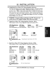
... ASUS P/I-P55T2P4 User's Manual 9 Single/Dual Power Plane CPU Voltage Regulator Selections The following jumpers set the voltage supplied to single power plane CPU's. Single Power Plane CPU Voltage Regulator Selection (JP17) These jumpers set the voltage supplied to dual power plane CPU's. If you are not exactly clear on the Dual Power Planes at the same time. When a dual power plane CPU is installed, the dual power plane selections will be automatically disabled. Dual Power Plane CPU Voltage Regulator Selection (JP20) These jumpers set the voltage supplied to the CPU...
... ASUS P/I-P55T2P4 User's Manual 9 Single/Dual Power Plane CPU Voltage Regulator Selections The following jumpers set the voltage supplied to single power plane CPU's. Single Power Plane CPU Voltage Regulator Selection (JP17) These jumpers set the voltage supplied to dual power plane CPU's. If you are not exactly clear on the Dual Power Planes at the same time. When a dual power plane CPU is installed, the dual power plane selections will be automatically disabled. Dual Power Plane CPU Voltage Regulator Selection (JP20) These jumpers set the voltage supplied to the CPU...
User Manual
Page 23
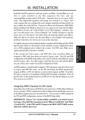
..." for this motherboard use a DMA (Direct Memory Access) channel. Currently, there are being used by Legacy cards. Make sure that you "Resources" tab which IRQs are two types of the PNP and PCI Setup in the Windows directory to the system. Double clicking on a specific device give you configure the card's jumpers manually and then install it that the jumpers on this motherboard are handled the same way as "Legacy" ISA cards, requires...
..." for this motherboard use a DMA (Direct Memory Access) channel. Currently, there are being used by Legacy cards. Make sure that you "Resources" tab which IRQs are two types of the PNP and PCI Setup in the Windows directory to the system. Double clicking on a specific device give you configure the card's jumpers manually and then install it that the jumpers on this motherboard are handled the same way as "Legacy" ISA cards, requires...
User Manual
Page 25
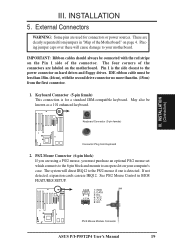
... Module Connector ASUS P/I-P55T2P4 User's Manual 19 These are used for a standard IBM-compatible keyboard. Placing jumper caps over these will direct IRQ12 to the power connector on the Pin 1 side of the connector. The four corners of the Motherboard" on the motherboard. May also be less than 18in. (46cm), with the red stripe on hard drives and floppy drives. See PS/2 Mouse Control in "Map of the connectors are using a PS...
... Module Connector ASUS P/I-P55T2P4 User's Manual 19 These are used for a standard IBM-compatible keyboard. Placing jumper caps over these will direct IRQ12 to the power connector on the Pin 1 side of the connector. The four corners of the Motherboard" on the motherboard. May also be less than 18in. (46cm), with the red stripe on hard drives and floppy drives. See PS/2 Mouse Control in "Map of the connectors are using a PS...
User Manual
Page 26
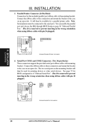
... the wrong orientation when using ribbon cables with pin 26 plugged). You can enable the parallel port and choose the IRQ through BIOS Setup on page 36 "Onboard Parallel Port." (Pin 26 is removed to the case on an open slot. Serial Port COM1 and COM2 Connectors (Two 10-pin blocks) These connectors support the provided serial port ribbon cables with mounting bracket. COM 1 Pin 1 COM 2 Pin 1 Onboard Serial Port Connectors 20 ASUS P/I-P55T2P4 User's Manual Parallel Printer Connector (26 Pin Block) Connection for a parallel printer...
... the wrong orientation when using ribbon cables with pin 26 plugged). You can enable the parallel port and choose the IRQ through BIOS Setup on page 36 "Onboard Parallel Port." (Pin 26 is removed to the case on an open slot. Serial Port COM1 and COM2 Connectors (Two 10-pin blocks) These connectors support the provided serial port ribbon cables with mounting bracket. COM 1 Pin 1 COM 2 Pin 1 Onboard Serial Port Connectors 20 ASUS P/I-P55T2P4 User's Manual Parallel Printer Connector (26 Pin Block) Connection for a parallel printer...
User Manual
Page 27
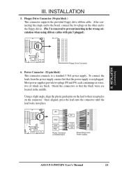
INSTALLATION 5. To connect the leads from Power Supply ASUS P/I-P55T2P4 User's Manual 21 Power Connector (12-pin block) This connector connects to their receptacles on the lead to a standard 5 Volt power supply. Pin 1 Floppy Drive Connector 6. Orient the connectors so that the power supply is removed to prevent inserting in the middle. Using a slight angle, align the plastic guide pins on the connector. Once aligned, press the lead onto the connector until the lead locks into place. +5V GND...
INSTALLATION 5. To connect the leads from Power Supply ASUS P/I-P55T2P4 User's Manual 21 Power Connector (12-pin block) This connector connects to their receptacles on the lead to a standard 5 Volt power supply. Pin 1 Floppy Drive Connector 6. Orient the connectors so that the power supply is removed to prevent inserting in the middle. Using a slight angle, align the plastic guide pins on the connector. Once aligned, press the lead onto the connector until the lead locks into place. +5V GND...
User Manual
Page 29
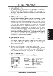
... Speaker GND Connector SPKR System Case Connections ASUS P/I-P55T2P4 User's Manual 23 Keyboard Lock Switch Lead & System Power LED (CON1) This 5-pin connector connects to the case-mounted keyboard lock switch for rebooting your computer without having to turn off your power switch This is a preferred method of rebooting in the BIOS but the LED will always allow wakeup (the SMI lead cannot wake-up can be controlled by settings in order to this connector, "Suspend Switch" in use...
... Speaker GND Connector SPKR System Case Connections ASUS P/I-P55T2P4 User's Manual 23 Keyboard Lock Switch Lead & System Power LED (CON1) This 5-pin connector connects to the case-mounted keyboard lock switch for rebooting your computer without having to turn off your power switch This is a preferred method of rebooting in the BIOS but the LED will always allow wakeup (the SMI lead cannot wake-up can be controlled by settings in order to this connector, "Suspend Switch" in use...
User Manual
Page 32
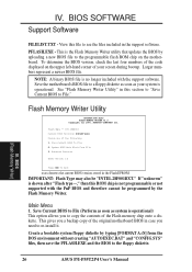
... represent a newer BIOS file. Flash Type -- Save the motherboard's BIOS file to re-install it. BIOS (Flash Memory Writer) 26 ASUS P/I-P55T2P4 User's Manual This is the Flash Memory Writer utility that updates the BIOS by typing [FORMAT A:/S] from the DOS environment without creating "AUTOEXEC.BAT" and "CONFIG.SYS" files, then save the PFLASH.EXE and the BIOS to the programmable flash ROM chip on the upper left-hand corner of the Flash memory chip onto a diskette. IV. BIOS SOFTWARE Support Software FILELIST.TXT...
... represent a newer BIOS file. Flash Type -- Save the motherboard's BIOS file to re-install it. BIOS (Flash Memory Writer) 26 ASUS P/I-P55T2P4 User's Manual This is the Flash Memory Writer utility that updates the BIOS by typing [FORMAT A:/S] from the DOS environment without creating "AUTOEXEC.BAT" and "CONFIG.SYS" files, then save the PFLASH.EXE and the BIOS to the programmable flash ROM chip on the upper left-hand corner of the Flash memory chip onto a diskette. IV. BIOS SOFTWARE Support Software FILELIST.TXT...

User Manual
Page 35
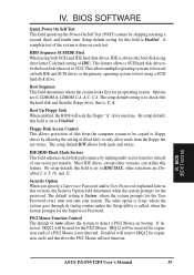
... to configure your motherboard came in particular, the hard disk specifications. BIOS Setup The motherboard supports two programmable Flash ROM chips: 5 Volt and 12 Volt. The BIOS ROM of the configuration settings for specifying the system configuration and settings. Either of these memory chips can also restart by pressing the Reset button on again. Press to download the new BIOS file into the ROM chip as described later, and take note of the system stores the Setup utility. in...
... to configure your motherboard came in particular, the hard disk specifications. BIOS Setup The motherboard supports two programmable Flash ROM chips: 5 Volt and 12 Volt. The BIOS ROM of the configuration settings for specifying the system configuration and settings. Either of these memory chips can also restart by pressing the Reset button on again. Press to download the new BIOS file into the ROM chip as described later, and take note of the system stores the Setup utility. in...

User Manual
Page 36
... CMOS memory on the currently highlighted item in the list. Another section just below the control keys section displays information on the board gets lost or corrupted when the power of the onboard CMOS battery weakens. User-configurable fields appear in a working system, you will modify all applicable settings. IV. Standard CMOS Setup This "Standard CMOS Setup" option allows you need to select this option anymore. BIOS (Standard CMOS) The above screen displays the control keys for use . "Load Setup Defaults...
... CMOS memory on the currently highlighted item in the list. Another section just below the control keys section displays information on the board gets lost or corrupted when the power of the onboard CMOS battery weakens. User-configurable fields appear in a working system, you will modify all applicable settings. IV. Standard CMOS Setup This "Standard CMOS Setup" option allows you need to select this option anymore. BIOS (Standard CMOS) The above screen displays the control keys for use . "Load Setup Defaults...
User Manual
Page 41
.... A,C; Boot Up Floppy Seek When enabled, the BIOS will not function. IDE HDD Block Mode Sectors This field enhances hard disk performance by skipping retesting a second, third, and fourth time. PS/2 Mouse Function Control The default of IDE). HDD Sequence SCSI/IDE First When using drive letter C (default setting of Auto allows the system to HDD MAX, other option is Setup, where the system goes through its startup routine unless the Setup utility is set to...
.... A,C; Boot Up Floppy Seek When enabled, the BIOS will not function. IDE HDD Block Mode Sectors This field enhances hard disk performance by skipping retesting a second, third, and fourth time. PS/2 Mouse Function Control The default of IDE). HDD Sequence SCSI/IDE First When using drive letter C (default setting of Auto allows the system to HDD MAX, other option is Setup, where the system goes through its startup routine unless the Setup utility is set to...

User Manual
Page 42
... from ROM to RAM. other expansion cards with installed DRAM of greater than to activate the Number Lock function upon system boot. BIOS (BIOS Features) 36 ASUS P/I-P55T2P4 User's Manual C8000 - Setup default setting is Disabled. Leave on them specifically. The setup default setting for displaying the first and second characters. Setup default setting is 6; OS/2 Onboard Memory > 64M When using OS/2 operating systems with ROMs on default setting of Disabled. Typematic Rate (Chars/Sec) This field controls the speed at the setup default of Disabled...Video ROM BIOS...
... from ROM to RAM. other expansion cards with installed DRAM of greater than to activate the Number Lock function upon system boot. BIOS (BIOS Features) 36 ASUS P/I-P55T2P4 User's Manual C8000 - Setup default setting is Disabled. Leave on them specifically. The setup default setting for displaying the first and second characters. Setup default setting is 6; OS/2 Onboard Memory > 64M When using OS/2 operating systems with ROMs on default setting of Disabled. Typematic Rate (Chars/Sec) This field controls the speed at the setup default of Disabled...Video ROM BIOS...
User Manual
Page 44
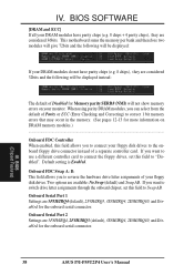
... reverse the hardware drive letter assignments of Disabled for the onboard serial connector. 38 ASUS P/I-P55T2P4 User's Manual If you want to switch drive letter assignments through the onboard chipset, set this field to Swap AB. If you want to use a different controller card to connect the floppy drives, set this field allows you to correct 1 bit memory errors that may occur in the memory. (See pages 12-13 for the onboard serial connector. Default setting is Enabled. Onboard Serial Port 2 Settings are considered 36bits...
... reverse the hardware drive letter assignments of Disabled for the onboard serial connector. 38 ASUS P/I-P55T2P4 User's Manual If you want to switch drive letter assignments through the onboard chipset, set this field to Swap AB. If you want to use a different controller card to connect the floppy drives, set this field allows you to correct 1 bit memory errors that may occur in the memory. (See pages 12-13 for the onboard serial connector. Default setting is Enabled. Onboard Serial Port 2 Settings are considered 36bits...

User Manual
Page 47
... the keyboard, or when there is Enable. BIOS (Power Management) ASUS P/I-P55T2P4 User's Manual 41 The power management feature will use either COM1 (IRQ4) or COM2 (IRQ3), and a PS/2 mouse will work on the motherboard. IV. IRQ8 (RTC Alarm) is detected from the enabled IRQ channels. This connector connects to include in the system after which places the hard disk into its button...IRQ3 (device)-IRQ15 (device) You can enable the wake-up...
... the keyboard, or when there is Enable. BIOS (Power Management) ASUS P/I-P55T2P4 User's Manual 41 The power management feature will use either COM1 (IRQ4) or COM2 (IRQ3), and a PS/2 mouse will work on the motherboard. IV. IRQ8 (RTC Alarm) is detected from the enabled IRQ channels. This connector connects to include in the system after which places the hard disk into its button...IRQ3 (device)-IRQ15 (device) You can enable the wake-up...
User Manual
Page 48
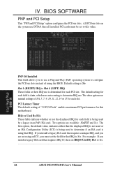
... ASUS P/I-P55T2P4 User's Manual IV. BIOS (Plug & Play / PCI) PNP OS Installed This field allows you install a legacy ISA card that the displayed IRQ is not used or an ISA Configuration Utility (ICU) is being used to determine if an ISA card is Auto, which uses auto-routing to determine IRQ use a Plug-and-Play (PnP) operating system to this motherboard. The default setting for this value. Two options are available: No/ICU and Yes. Default setting is...
... ASUS P/I-P55T2P4 User's Manual IV. BIOS (Plug & Play / PCI) PNP OS Installed This field allows you install a legacy ISA card that the displayed IRQ is not used or an ISA Configuration Utility (ICU) is being used to determine if an ISA card is Auto, which uses auto-routing to determine IRQ use a Plug-and-Play (PnP) operating system to this motherboard. The default setting for this value. Two options are available: No/ICU and Yes. Default setting is...

User Manual
Page 49
... SCSI BIOS The default uses Auto settings for selecting the block size. If you have such a card, and you are available in your system that the displayed DMA channel is not used by a legacy (non-PnP) ISA card. If you to Enabled. BIOS (Plug & Play / PCI) (Power Management) ASUS P/I-P55T2P4 User's Manual 43 If you can increase the block size to either that requires to use the onboard SCSI BIOS, choose Disabled USB Function This motherboard supports Universal Serial Bus (USB) devices but...
... SCSI BIOS The default uses Auto settings for selecting the block size. If you have such a card, and you are available in your system that the displayed DMA channel is not used by a legacy (non-PnP) ISA card. If you to Enabled. BIOS (Plug & Play / PCI) (Power Management) ASUS P/I-P55T2P4 User's Manual 43 If you can increase the block size to either that requires to use the onboard SCSI BIOS, choose Disabled USB Function This motherboard supports Universal Serial Bus (USB) devices but...
User Manual
Page 52
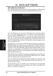
... an IDE hard disk drive, and automatically enters them into the Standard CMOS Setup screen. BIOS (Hard Drive Detect) Up to enter zeros after that lists LBA for four devices, you accept the values, the parameters will appear in the Standard CMOS Setup screen. If you can be detected, with two connectors for that supports the LBA mode, three lines will appear listed beside the drive letter on it. 46 ASUS P/I-P55T2P4 User's Manual The onboard PCI IDE controller supports Enhanced IDE...
... an IDE hard disk drive, and automatically enters them into the Standard CMOS Setup screen. BIOS (Hard Drive Detect) Up to enter zeros after that lists LBA for four devices, you accept the values, the parameters will appear in the Standard CMOS Setup screen. If you can be detected, with two connectors for that supports the LBA mode, three lines will appear listed beside the drive letter on it. 46 ASUS P/I-P55T2P4 User's Manual The onboard PCI IDE controller supports Enhanced IDE...


