
User Manual
Page 1
R P/I-P55T2P4 Pentium Motherboard USER'S MANUAL
R P/I-P55T2P4 Pentium Motherboard USER'S MANUAL

User Manual
Page 4
...Power Connection Procedures 25 IV. INSTALLATION 4 Map of the ASUS Motherboard 3 III. Central Processing Unit (CPU 15 4. FEATURES 2 Features of the ASUS Motherboard 2 Parts of the Motherboard 4 Installation Steps 6 1. BIOS SOFTWARE 26 Support Software 26...Motherboard's BIOS 28 6. System Memory (DRAM & SRAM 12 TAG SRAM Upgrade 12 DRAM Memory Installation Procedures 13 Static RAM (SRAM) for Level 2 (External) Cache 14 Compatible Cache Modules for ISA Cards 17 ASUS MediaBus Card 18 5. Jumpers 6 Jumper Settings 7 Cyrix CPU Identification 11 2. CONTENTS I -P55T2P4...
...Power Connection Procedures 25 IV. INSTALLATION 4 Map of the ASUS Motherboard 3 III. Central Processing Unit (CPU 15 4. FEATURES 2 Features of the ASUS Motherboard 2 Parts of the Motherboard 4 Installation Steps 6 1. BIOS SOFTWARE 26 Support Software 26...Motherboard's BIOS 28 6. System Memory (DRAM & SRAM 12 TAG SRAM Upgrade 12 DRAM Memory Installation Procedures 13 Static RAM (SRAM) for Level 2 (External) Cache 14 Compatible Cache Modules for ISA Cards 17 ASUS MediaBus Card 18 5. Jumpers 6 Jumper Settings 7 Cyrix CPU Identification 11 2. CONTENTS I -P55T2P4...

User Manual
Page 7
...: Information and specifications concerning this manual is organized This manual is complete. Installation: Instructions on the included support software VI. The ASUS P/I-P55T2P4 motherboard 2 serial port ribbon cables attached to a mounting bracket 1 parallel ribbon cable with mounting bracket 1 IDE ribbon cable 1 floppy ribbon cable Support drivers and utilities as ...
...: Information and specifications concerning this manual is organized This manual is complete. Installation: Instructions on the included support software VI. The ASUS P/I-P55T2P4 motherboard 2 serial port ribbon cables attached to a mounting bracket 1 parallel ribbon cable with mounting bracket 1 IDE ribbon cable 1 floppy ribbon cable Support drivers and utilities as ...

User Manual
Page 8
...also supported without an external card. Two floppy drives of the ASUS Motherboard The ASUS P/I-P55T2P4 is also supported. 2 ASUS P/I-P55T2P4 User's Manual FEATURES Features of either a standard PCI card or the ASUS MediaBus Card. • ASUS MediaBus Rev 2.0: Features an expansion slot extension shared with PCI Slot... /O subsystems. • Error Checking and Correcting (ECC): Using Intel's 430HX PCIset together with EPP and ECP capabilities. This motherboard: • Easy Installation: Is equipped with BIOS that supports auto detection of hard drives and Plug and Play to make setup...
...also supported without an external card. Two floppy drives of the ASUS Motherboard The ASUS P/I-P55T2P4 is also supported. 2 ASUS P/I-P55T2P4 User's Manual FEATURES Features of either a standard PCI card or the ASUS MediaBus Card. • ASUS MediaBus Rev 2.0: Features an expansion slot extension shared with PCI Slot... /O subsystems. • Error Checking and Correcting (ECC): Using Intel's 430HX PCIset together with EPP and ECP capabilities. This motherboard: • Easy Installation: Is equipped with BIOS that supports auto detection of hard drives and Plug and Play to make setup...

User Manual
Page 9
FEATURES (Parts of the ASUS Motherboard 3 ISA Slots Programmable Flash ROM 3 PCI Slots Parallel & Serial Ports Super Multi-I -P55T2P4 User's Manual 3 BIOS supports IDE CD-ROM and SCSI bootup. • Optional IrDA and PS/2 Mouse Connector: This motherboard supports an optional infrared port module for wireless interface and a PS/2 mouse cable set. • NCR SCSI...
FEATURES (Parts of the ASUS Motherboard 3 ISA Slots Programmable Flash ROM 3 PCI Slots Parallel & Serial Ports Super Multi-I -P55T2P4 User's Manual 3 BIOS supports IDE CD-ROM and SCSI bootup. • Optional IrDA and PS/2 Mouse Connector: This motherboard supports an optional infrared port module for wireless interface and a PS/2 mouse cable set. • NCR SCSI...

User Manual
Page 10
... Slot 1 SIMM Socket 4 (Bank 1) SIMM Socket 3 (Bank 1) SIMM Socket 2 (Bank 0) SIMM Socket 1 (Bank 0) III. INSTALLATION (Map of the ASUS Motherboard ISA Slot 2 ISA Slot 3 JP2 Boot Block Write (Dis/En) PS/2 Mouse Keyboard Universal Serial Bus (Reserved for future use) COM 1 COM 2 Serial (COM...) Ports MULTI I/O Chipset Multi-I -P55T2P4 User's Manual III. INSTALLATION Map of Board) Board Power Input P9 Secondary IDE Primary IDE Floppy Drives P8 MediaBus 2.0 Pipelined Burst Level...
... Slot 1 SIMM Socket 4 (Bank 1) SIMM Socket 3 (Bank 1) SIMM Socket 2 (Bank 0) SIMM Socket 1 (Bank 0) III. INSTALLATION (Map of the ASUS Motherboard ISA Slot 2 ISA Slot 3 JP2 Boot Block Write (Dis/En) PS/2 Mouse Keyboard Universal Serial Bus (Reserved for future use) COM 1 COM 2 Serial (COM...) Ports MULTI I/O Chipset Multi-I -P55T2P4 User's Manual III. INSTALLATION Map of Board) Board Power Input P9 Secondary IDE Primary IDE Floppy Drives P8 MediaBus 2.0 Pipelined Burst Level...

User Manual
Page 11
...JP5 4) JP7 5) JP17 6) JP20 7) JP8, JP9,JP10 8) JP11, JP12 9) JP4 p. 7 Multi-I -P55T2P4 User's Manual 5 IDE p. 22 8) IDE LED p. 22 9) Turbo/Power (CON1) p. 23 10) ... Serial Port COM1 & COM2 (10-pin Blocks) Floppy Drive Connector (34-pin Block) Motherboard Power Connector (12-pin Block) Primary/Secondary IDE Connectors (40-pin Blocks) IDE LED Activity... (2-pins) Keyboard Lock Switch Lead (5-pins) Speaker Connector (4-pins) CPU 12V Cooling Fan Connector Infrared Port Module Connector ASUS P/I /O Selection (Enable/Disable) p. 7 Flash ROM Boot Block Program (Disable/Enable) p. 8 Total Level 2 ...
...JP5 4) JP7 5) JP17 6) JP20 7) JP8, JP9,JP10 8) JP11, JP12 9) JP4 p. 7 Multi-I -P55T2P4 User's Manual 5 IDE p. 22 8) IDE LED p. 22 9) Turbo/Power (CON1) p. 23 10) ... Serial Port COM1 & COM2 (10-pin Blocks) Floppy Drive Connector (34-pin Block) Motherboard Power Connector (12-pin Block) Primary/Secondary IDE Connectors (40-pin Blocks) IDE LED Activity... (2-pins) Keyboard Lock Switch Lead (5-pins) Speaker Connector (4-pins) CPU 12V Cooling Fan Connector Infrared Port Module Connector ASUS P/I /O Selection (Enable/Disable) p. 7 Flash ROM Boot Block Program (Disable/Enable) p. 8 Total Level 2 ...

User Manual
Page 12
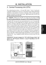
...connect pins 2&3. For manufacturing simplicity, the jumpers may be sharing pins from the system. 6 ASUS P/I-P55T2P4 User's Manual Use the diagrams in this manual instead of the Motherboard" on the board. Install the Central Processing Unit (CPU) 4. Jumpers Several hardware settings ...Cards 5. Pin 1 for no connection, connect pins 1&2, and connect pins 2&3 respec- A "1" is always on top or on the motherboard. Settings with two pins will also be moved together. WARNING: Computer motheboards and components contain very delicate Integrated Circuit (IC) chips. INSTALLATION...
...connect pins 2&3. For manufacturing simplicity, the jumpers may be sharing pins from the system. 6 ASUS P/I-P55T2P4 User's Manual Use the diagrams in this manual instead of the Motherboard" on the board. Install the Central Processing Unit (CPU) 4. Jumpers Several hardware settings ...Cards 5. Pin 1 for no connection, connect pins 1&2, and connect pins 2&3 respec- A "1" is always on top or on the motherboard. Settings with two pins will also be moved together. WARNING: Computer motheboards and components contain very delicate Integrated Circuit (IC) chips. INSTALLATION...

User Manual
Page 14
... RAM (Operation / Clear Data) 8 ASUS P/I-P55T2P4 User's Manual An "ASUS" or "COAST" cache module can be used to upgrade the 256KB version to re-enter user preferences. IMPORTANT: See page 14 "SRAM Cache" for locations) and a Cache Expansion Slot, then you have both onboard cache chips (see "Map of Motherboard" for installation procedures. To...
... RAM (Operation / Clear Data) 8 ASUS P/I-P55T2P4 User's Manual An "ASUS" or "COAST" cache module can be used to upgrade the 256KB version to re-enter user preferences. IMPORTANT: See page 14 "SRAM Cache" for locations) and a Cache Expansion Slot, then you have both onboard cache chips (see "Map of Motherboard" for installation procedures. To...

User Manual
Page 16
...send to BUS Frequency Ratio (JP11, JP12) These jumpers set together with the Cyrix PR166+ installed on this motherboard. 10 ASUS P/I-P55T2P4 User's Manual Bootup screen will show 6x86-P166+ with the above jumpers CPU External (BUS) Frequency Selection....[2-3] [2-3] [1-2] [2-3] [2-3] [2-3] [2-3] *IBM/Cyrix6x86-PR166+ 133MHz 2.0x 66MHz [2-3] [1-2] [2-3] [1-2] [2-3] *NOTE: Only IBM or Cyrix Rev 2.7 or later is supported on this motherboard (see next page). These allow the selection of the CPU and the External frequency (called the BUS Clock) within the CPU. III. The BUS Clock...
...send to BUS Frequency Ratio (JP11, JP12) These jumpers set together with the Cyrix PR166+ installed on this motherboard. 10 ASUS P/I-P55T2P4 User's Manual Bootup screen will show 6x86-P166+ with the above jumpers CPU External (BUS) Frequency Selection....[2-3] [2-3] [1-2] [2-3] [2-3] [2-3] [2-3] *IBM/Cyrix6x86-PR166+ 133MHz 2.0x 66MHz [2-3] [1-2] [2-3] [1-2] [2-3] *NOTE: Only IBM or Cyrix Rev 2.7 or later is supported on this motherboard (see next page). These allow the selection of the CPU and the External frequency (called the BUS Clock) within the CPU. III. The BUS Clock...

User Manual
Page 17
... Motherboard" on page 4 for the serial number. See "Map of the CPU for L2 cache locations. Cacheable Size 64MB (BSRAM/MCache) 512MB (BSRAM Only) JP4 [1-2] (Default) [2-3] JP4 123 64MB Cacheable (Default) Burst SRAM or MCache JP4 123 512MB Cacheable Burst SRAM Only Cacheable Size (64MB/512MB) ASUS P/I-P55T2P4 ... 14 for cache module information. Memory Cacheable Size (JP4) The default of pipelined burst SRAM chips, this jumper must be set this motherboard is labeled Cyrix 6x86-PR166+ but not both and set to 64MB. If you install DRAM above 64MB and wish to allow cacheable...
... Motherboard" on page 4 for the serial number. See "Map of the CPU for L2 cache locations. Cacheable Size 64MB (BSRAM/MCache) 512MB (BSRAM Only) JP4 [1-2] (Default) [2-3] JP4 123 64MB Cacheable (Default) Burst SRAM or MCache JP4 123 512MB Cacheable Burst SRAM Only Cacheable Size (64MB/512MB) ASUS P/I-P55T2P4 ... 14 for cache module information. Memory Cacheable Size (JP4) The default of pipelined burst SRAM chips, this jumper must be set this motherboard is labeled Cyrix 6x86-PR166+ but not both and set to 64MB. If you install DRAM above 64MB and wish to allow cacheable...

User Manual
Page 18
... generated by "Memory Cacheable Size" jumper. The DRAM can be unstable. IMPORTANT: Each bank must use true (opposed to 256MB. System Memory (DRAM & SRAM) This motherboard supports four 72-pin SIMMs of this SRAM is 15ns or faster. To support ECC, you install already have the same size memory installed in... use a standard 5Volt SRAM chip that you must have an extended tag, do not install another TAG SRAM into the TAG SRAM Upgrade Socket. 12 ASUS P/I-P55T2P4 User's Manual INSTALLATION 2.
... generated by "Memory Cacheable Size" jumper. The DRAM can be unstable. IMPORTANT: Each bank must use true (opposed to 256MB. System Memory (DRAM & SRAM) This motherboard supports four 72-pin SIMMs of this SRAM is 15ns or faster. To support ECC, you install already have the same size memory installed in... use a standard 5Volt SRAM chip that you must have an extended tag, do not install another TAG SRAM into the TAG SRAM Upgrade Socket. 12 ASUS P/I-P55T2P4 User's Manual INSTALLATION 2.

User Manual
Page 20
...shown. INSTALLATION Static RAM (SRAM) for Level 2 (External) Cache The motherboard you have either 0KB, 256KB, or 512KB onboard. Because the number of Motherboard" for this Motherboard SIMM Cache Module ASUS CM1 Rev 1.0 ASUS CM1 Rev 1.3 ASUS CM4 Rev 1.5 ASUS CM1 Rev 1.6 ASUS CM1 Rev 3.0 COAST 1.1 COAST 1.2 COAST 1.3 COAST 2.0 COAST 2.1 ...Cache Expansion Slot, then you have an extended tag, do not install another TAG SRAM into the TAG SRAM Upgrade Socket. 14 ASUS P/I-P55T2P4 User's Manual If you have both onboard cache chips (see "Map of pins are made to your cache size. 42 Pins...
...shown. INSTALLATION Static RAM (SRAM) for Level 2 (External) Cache The motherboard you have either 0KB, 256KB, or 512KB onboard. Because the number of Motherboard" for this Motherboard SIMM Cache Module ASUS CM1 Rev 1.0 ASUS CM1 Rev 1.3 ASUS CM4 Rev 1.5 ASUS CM1 Rev 1.6 ASUS CM1 Rev 3.0 COAST 1.1 COAST 1.2 COAST 1.3 COAST 2.0 COAST 2.1 ...Cache Expansion Slot, then you have an extended tag, do not install another TAG SRAM into the TAG SRAM Upgrade Socket. 14 ASUS P/I-P55T2P4 User's Manual If you have both onboard cache chips (see "Map of pins are made to your cache size. 42 Pins...
User Manual
Page 21
...fan attached to insert the CPU. Notice that you install. With the added weight of the CPU fan, no force is backwards compatible with the motherboard should have a CPU fan that corner of the square array of the CPU. Use the notched corner of the lever. Lever Lock Blank 1 ...motherboard provides a 321-pin ZIF Socket 7 that is required to it by first pulling the lever sideways away from that will only fit in the one hole is not the case then purchase a fan before you should point towards the end the of the CPU with Pentium Processor 1 White Dot ASUS P/I-P55T2P4...
...fan attached to insert the CPU. Notice that you install. With the added weight of the CPU fan, no force is backwards compatible with the motherboard should have a CPU fan that corner of the square array of the CPU. Use the notched corner of the lever. Lever Lock Blank 1 ...motherboard provides a 321-pin ZIF Socket 7 that is required to it by first pulling the lever sideways away from that will only fit in the one hole is not the case then purchase a fan before you should point towards the end the of the CPU with Pentium Processor 1 White Dot ASUS P/I-P55T2P4...
User Manual
Page 22
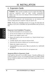
Remove your motherboard and expansion cards. Setup the BIOS if necessary (such as "IRQ xx Used By ISA: Yes" in use . Generally an IRQ must be required to use by parts of the system which leaves 6 free for expansion cards. 16 ASUS P/I-P55T2P4 User's Manual Expansion Cards WARNING: Make sure that may cause severe...
Remove your motherboard and expansion cards. Setup the BIOS if necessary (such as "IRQ xx Used By ISA: Yes" in use . Generally an IRQ must be required to use by parts of the system which leaves 6 free for expansion cards. 16 ASUS P/I-P55T2P4 User's Manual Expansion Cards WARNING: Make sure that may cause severe...
User Manual
Page 23
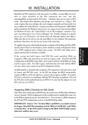
... then install it that no two devices use a DMA (Direct Memory Access) channel. You may occur. To simplify this process this motherboard has complied with the BIOS, you "Resources" tab which was developed to allow automatic system configuration whenever a PNP-compliant card is automatically...IRQs are being used by Legacy cards. To install a PCI card, you a "Device Manager" tab. DMA assignments for this motherboard use at the same time. ASUS P/I-P55T2P4 User's Manual 17 For Windows 95 users, the "Control Panel" icon in the ISA expansion bus first, and any available slot...
... then install it that no two devices use a DMA (Direct Memory Access) channel. You may occur. To simplify this process this motherboard has complied with the BIOS, you "Resources" tab which was developed to allow automatic system configuration whenever a PNP-compliant card is automatically...IRQs are being used by Legacy cards. To install a PCI card, you a "Device Manager" tab. DMA assignments for this motherboard use at the same time. ASUS P/I-P55T2P4 User's Manual 17 For Windows 95 users, the "Control Panel" icon in the ISA expansion bus first, and any available slot...
User Manual
Page 24
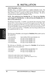
... one add-on card is that can meet standard specifications. The following are MediaBus cards designed for MediaBus 1.2 and therefore cannot be used on this motherboard: • PCI-AS7870 • PCI-AV264CT • PCI-AV868 Fast/Wide SCSI & Audio MediaBus Card PCI Audio & Video MediaBus Card PCI Audio & Video MediaBus Card... Audio features Creative Technology, Ltd. * All the above Video features ATI, Inc. (AV868 Video features S3, Inc.) * All the above SCSI features Adaptec, Inc. 18 ASUS P/I-P55T2P4 User's Manual INSTALLATION (MediaBus Card) III. III.
... one add-on card is that can meet standard specifications. The following are MediaBus cards designed for MediaBus 1.2 and therefore cannot be used on this motherboard: • PCI-AS7870 • PCI-AV264CT • PCI-AV868 Fast/Wide SCSI & Audio MediaBus Card PCI Audio & Video MediaBus Card PCI Audio & Video MediaBus Card... Audio features Creative Technology, Ltd. * All the above Video features ATI, Inc. (AV868 Video features S3, Inc.) * All the above SCSI features Adaptec, Inc. 18 ASUS P/I-P55T2P4 User's Manual INSTALLATION (MediaBus Card) III. III.
User Manual
Page 25
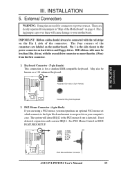
... will direct IRQ12 to an open slot on your motherboard. Pin 1 is the side closest to your computer's case. INSTALLATION (Connectors) Connector Plug from jumpers in BIOS FEATURES SETUP. 1 234 58 1 234 58 1: GND 2: DATA 3: NC 4: VCC 5: CLK 8: NC PS/2 Mouse Module Connector ASUS P/I-P55T2P4 User's Manual 19 If not detected, expansion cards...
... will direct IRQ12 to an open slot on your motherboard. Pin 1 is the side closest to your computer's case. INSTALLATION (Connectors) Connector Plug from jumpers in BIOS FEATURES SETUP. 1 234 58 1 234 58 1: GND 2: DATA 3: NC 4: VCC 5: CLK 8: NC PS/2 Mouse Module Connector ASUS P/I-P55T2P4 User's Manual 19 If not detected, expansion cards...
User Manual
Page 27
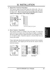
... lead to their receptacles on the other end to the board, connect the two plugs on the connector. To connect the leads from Power Supply ASUS P/I-P55T2P4 User's Manual 21 Floppy Drive Connector (34-pin block ) This connector supports the provided floppy drive ribbon cable. Power Connector (12-pin block) This ... in the middle. Once aligned, press the lead onto the connector until the lead locks into place. +5V GND +12V PG Power Connector on Motherboard P9 -5V -12V +5V RED RED RED WHT BLK BLK BLK BLK BLU YLW RED ORG P8 Power Plugs from the power supply, ensure first...
... lead to their receptacles on the other end to the board, connect the two plugs on the connector. To connect the leads from Power Supply ASUS P/I-P55T2P4 User's Manual 21 Floppy Drive Connector (34-pin block ) This connector supports the provided floppy drive ribbon cable. Power Connector (12-pin block) This ... in the middle. Once aligned, press the lead onto the connector until the lead locks into place. +5V GND +12V PG Power Connector on Motherboard P9 -5V -12V +5V RED RED RED WHT BLK BLK BLK BLK BLU YLW RED ORG P8 Power Plugs from the power supply, ensure first...
User Manual
Page 29
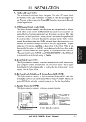
... SPKR System Case Connections ASUS P/I-P55T2P4 User's Manual 23 This 2-pin connector (see the figure below . 12. If you want to the case-mounted suspend switch. You may use this lead. If you do not have a function. SMI is always on . INSTALLATION (Connectors) III. Turbo LED Lead (CON1) The motherboard's turbo function is...
... SPKR System Case Connections ASUS P/I-P55T2P4 User's Manual 23 This 2-pin connector (see the figure below . 12. If you want to the case-mounted suspend switch. You may use this lead. If you do not have a function. SMI is always on . INSTALLATION (Connectors) III. Turbo LED Lead (CON1) The motherboard's turbo function is...


