
User Manual
Page 1
R P/I-P55T2P4 Pentium Motherboard USER'S MANUAL
R P/I-P55T2P4 Pentium Motherboard USER'S MANUAL
User Manual
Page 2
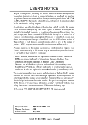
... profits, loss of business, loss of use or data, interruption of any defect or error in the manual revision number. Product Name: ASUS P/I-P55T2P4 Manual Revision: 3.11 Release Date: May 1997 II ASUS P/I-P55T2P4 User's Manual In no event shall ASUS be registered trademarks or copyrights of their respective companies. • Intel, LANDesk, and Pentium are registered trademarks...
... profits, loss of business, loss of use or data, interruption of any defect or error in the manual revision number. Product Name: ASUS P/I-P55T2P4 Manual Revision: 3.11 Release Date: May 1997 II ASUS P/I-P55T2P4 User's Manual In no event shall ASUS be registered trademarks or copyrights of their respective companies. • Intel, LANDesk, and Pentium are registered trademarks...
User Manual
Page 3
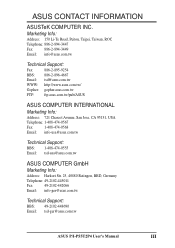
...: Fax: 886-2-895-9254 BBS: 886-2-896-4667 Email: tsd@asus.com.tw WWW: http://www.asus.com.tw/ Gopher: gopher.asus.com.tw FTP: ftp.asus.com.tw/pub/ASUS ASUS COMPUTER INTERNATIONAL Marketing Info: Address: 721 Charcot Avenue, San Jose, CA...asus.com.tw Technical Support: BBS: 1-408-474-0555 Email: tsd-usa@asus.com.tw ASUS COMPUTER GmbH Marketing Info: Address: Harkort Str. 25, 40880 Ratingen, BRD, Germany Telephone: 49-2102-445011 Fax: 49-2102-442066 Email: info-ger@asus.com.tw Technical Support: BBS: 49-2102-448690 Email: tsd-ger@asus.com.tw ASUS P/I-P55T2P4 User's Manual...
...: Fax: 886-2-895-9254 BBS: 886-2-896-4667 Email: tsd@asus.com.tw WWW: http://www.asus.com.tw/ Gopher: gopher.asus.com.tw FTP: ftp.asus.com.tw/pub/ASUS ASUS COMPUTER INTERNATIONAL Marketing Info: Address: 721 Charcot Avenue, San Jose, CA...asus.com.tw Technical Support: BBS: 1-408-474-0555 Email: tsd-usa@asus.com.tw ASUS COMPUTER GmbH Marketing Info: Address: Harkort Str. 25, 40880 Ratingen, BRD, Germany Telephone: 49-2102-445011 Fax: 49-2102-442066 Email: info-ger@asus.com.tw Technical Support: BBS: 49-2102-448690 Email: tsd-ger@asus.com.tw ASUS P/I-P55T2P4 User's Manual...

User Manual
Page 4
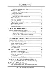
... Power Connection Procedures 25 IV. BIOS Setup 29 Load Defaults 30 Standard CMOS Setup 30 IV ASUS P/I . INSTALLATION 4 Map of the ASUS Motherboard 3 III. INTRODUCTION 1 How this Motherboard 14 3. Central Processing Unit (CPU 15 4. CONTENTS I -P55T2P4 User's Manual Expansion Cards 16 Expansion Card Installation Procedure 16 Assigning IRQs for Expansion Cards 16 Assigning DMA...
... Power Connection Procedures 25 IV. BIOS Setup 29 Load Defaults 30 Standard CMOS Setup 30 IV ASUS P/I . INSTALLATION 4 Map of the ASUS Motherboard 3 III. INTRODUCTION 1 How this Motherboard 14 3. Central Processing Unit (CPU 15 4. CONTENTS I -P55T2P4 User's Manual Expansion Cards 16 Expansion Card Installation Procedure 16 Assigning IRQs for Expansion Cards 16 Assigning DMA...
User Manual
Page 5
...) ASUS P/I-P55T2P4 User's Manual V ASUS PCI-SC200 SCSI Card 53 NCR SCSI BIOS and Drivers 53 The ASUS PCI-SC200 SCSI Interface Card 54 Setting Up the ASUS PCI-SC200 54 Setting the INT Assignment 55 Terminator Settings 55 SCSI ID Numbers 56 VII. ASUS I-A16C Audio Card 57 ASUS ... DESKTOP MANAGEMENT 49 Desktop Management Interface (DMI 49 Introducing the ASUS DMI Configuration Utility 49 System Requirements 49 Using the ASUS DMI Configuration Utility 50 Notes 50 VI. Windows 95 Audio Software (with optional ASUS I -A16C Audio Features 57 Unpacking and Handling Precautions 57 ...
...) ASUS P/I-P55T2P4 User's Manual V ASUS PCI-SC200 SCSI Card 53 NCR SCSI BIOS and Drivers 53 The ASUS PCI-SC200 SCSI Interface Card 54 Setting Up the ASUS PCI-SC200 54 Setting the INT Assignment 55 Terminator Settings 55 SCSI ID Numbers 56 VII. ASUS I-A16C Audio Card 57 ASUS ... DESKTOP MANAGEMENT 49 Desktop Management Interface (DMI 49 Introducing the ASUS DMI Configuration Utility 49 System Requirements 49 Using the ASUS DMI Configuration Utility 50 Notes 50 VI. Windows 95 Audio Software (with optional ASUS I -A16C Audio Features 57 Unpacking and Handling Precautions 57 ...
User Manual
Page 6
... device must accept any interference received, including interference that interference will not occur in a residential installation. These limits are designed to radio communications. VI ASUS P/I-P55T2P4 User's Manual If this equipment. This equipment has been tested and found to comply with FCC Rules Part 15. FCC & DOC COMPLIANCE Federal Communications Commission Statement This...
... device must accept any interference received, including interference that interference will not occur in a residential installation. These limits are designed to radio communications. VI ASUS P/I-P55T2P4 User's Manual If this equipment. This equipment has been tested and found to comply with FCC Rules Part 15. FCC & DOC COMPLIANCE Federal Communications Commission Statement This...

User Manual
Page 7
...manual is organized This manual is complete. DOS/Win3.1x: Audio Software Manual (with ASUS I -A16C: Installation of an optional ASUS SCSI cards VII. INTRODUCTION How this product III. ASUS I -A16C bundle) Item Checklist Please check that your retailer. Windows 95: Audio Software Manual (with ASUS I -P55T2P4 User's Manual 1 ASUS...your package is divided into the following sections: I. I . INTRODUCTION (Manual / Checklist) I . BIOS Setup: BIOS software setup information. The ASUS P/I-P55T2P4 motherboard 2 serial port ribbon cables attached to a mounting bracket 1 ...
...manual is organized This manual is complete. DOS/Win3.1x: Audio Software Manual (with ASUS I -A16C: Installation of an optional ASUS SCSI cards VII. INTRODUCTION How this product III. ASUS I -A16C bundle) Item Checklist Please check that your retailer. Windows 95: Audio Software Manual (with ASUS I -P55T2P4 User's Manual 1 ASUS...your package is divided into the following sections: I. I . INTRODUCTION (Manual / Checklist) I . BIOS Setup: BIOS software setup information. The ASUS P/I-P55T2P4 motherboard 2 serial port ribbon cables attached to a mounting bracket 1 ...

User Manual
Page 8
... standard protocol creating a higher level of compatibility (see section V). • L2 Cache: Provides the option of the ASUS Motherboard The ASUS P/I-P55T2P4 is also supported. 2 ASUS P/I /O: Provides two high-speed UART compatible serial ports and one parallel port with parity DRAM modules can also be...features in one easy-to-install card. (For revision compatibility information, please refer to page 18.) • Super Multi-I -P55T2P4 User's Manual FEATURES Features of 0KB upgradeable to 256KB or 512KB, onboard 256KB upgradeable to 256MB. UART2 can detect multi-bit memory errors ...
... standard protocol creating a higher level of compatibility (see section V). • L2 Cache: Provides the option of the ASUS Motherboard The ASUS P/I-P55T2P4 is also supported. 2 ASUS P/I /O: Provides two high-speed UART compatible serial ports and one parallel port with parity DRAM modules can also be...features in one easy-to-install card. (For revision compatibility information, please refer to page 18.) • Super Multi-I -P55T2P4 User's Manual FEATURES Features of 0KB upgradeable to 256KB or 512KB, onboard 256KB upgradeable to 256MB. UART2 can detect multi-bit memory errors ...

User Manual
Page 9
...Slots Parallel & Serial Ports Super Multi-I -P55T2P4 User's Manual 3 FEATURES • PCI Bus Master IDE Controller: Comes with an onboard PCI Bus Master IDE controller with two connectors that supports the optional ASUS PCI-SC200 SCSI controller cards. PCI 4 or ASUS MediaBus 2.0 (4) 72-pin SIMM Sockets ...SRAM Self-Powered RealTime Clock Intel's 430HX PCIset CPU ZIF Socket 7 L2 Upgrade Cache Expansion Slot Onboard 256KB/ 512KB Pipelined Burst L2 Cache ASUS P/I /O Onboard Floppy & IDE Connect. BIOS supports IDE CD-ROM and SCSI bootup. • Optional IrDA and PS/2 Mouse Connector...
...Slots Parallel & Serial Ports Super Multi-I -P55T2P4 User's Manual 3 FEATURES • PCI Bus Master IDE Controller: Comes with an onboard PCI Bus Master IDE controller with two connectors that supports the optional ASUS PCI-SC200 SCSI controller cards. PCI 4 or ASUS MediaBus 2.0 (4) 72-pin SIMM Sockets ...SRAM Self-Powered RealTime Clock Intel's 430HX PCIset CPU ZIF Socket 7 L2 Upgrade Cache Expansion Slot Onboard 256KB/ 512KB Pipelined Burst L2 Cache ASUS P/I /O Onboard Floppy & IDE Connect. BIOS supports IDE CD-ROM and SCSI bootup. • Optional IrDA and PS/2 Mouse Connector...

User Manual
Page 10
... JP12 Case Connector Freq Ratio IDE LED Infrared Conn. III. CPU VCore JP20 12V Fan Power JP17 Voltage (STD/VRE) 256/512KB onboard L2 Cache 4 ASUS P/I /O (En/Dis) JP1 Parallel (Printer) Port PCI Slot 1 PCI Slot 2 PCI Slot 3 PCI Slot 4 ISA Slot 1 SIMM Socket 4 (Bank 1) SIMM ...Socket 3 (Bank 1) SIMM Socket 2 (Bank 0) SIMM Socket 1 (Bank 0) III. INSTALLATION (Map of the ASUS Motherboard ISA Slot 2 ISA Slot 3 JP2 Boot Block Write (Dis/En) PS/2 Mouse Keyboard Universal Serial Bus (Reserved for future use) COM 1 COM 2 Serial (COM...
... JP12 Case Connector Freq Ratio IDE LED Infrared Conn. III. CPU VCore JP20 12V Fan Power JP17 Voltage (STD/VRE) 256/512KB onboard L2 Cache 4 ASUS P/I /O (En/Dis) JP1 Parallel (Printer) Port PCI Slot 1 PCI Slot 2 PCI Slot 3 PCI Slot 4 ISA Slot 1 SIMM Socket 4 (Bank 1) SIMM ...Socket 3 (Bank 1) SIMM Socket 2 (Bank 0) SIMM Socket 1 (Bank 0) III. INSTALLATION (Map of the ASUS Motherboard ISA Slot 2 ISA Slot 3 JP2 Boot Block Write (Dis/En) PS/2 Mouse Keyboard Universal Serial Bus (Reserved for future use) COM 1 COM 2 Serial (COM...

User Manual
Page 11
INSTALLATION Jumpers 1) JP1 2) JP2 3) JP5 4) JP7 5) JP17 6) JP20 7) JP8, JP9,JP10 8) JP11, JP12 9) JP4 p. 7 Multi-I -P55T2P4 User's Manual 5 INSTALLATION (Map of Board) III. IDE p. 22 8) IDE LED p. 22 9) Turbo/Power (CON1) p. 23 10) SMI Switch (CON1) p. 23 ...) SMI Switch Lead (2-pins) Reset Switch Lead (2-pins) Keyboard Lock Switch Lead (5-pins) Speaker Connector (4-pins) CPU 12V Cooling Fan Connector Infrared Port Module Connector ASUS P/I /O Selection (Enable/Disable) p. 7 Flash ROM Boot Block Program (Disable/Enable) p. 8 Total Level 2 Cache Size Setting (256/512KB) p. 8 Real ...
INSTALLATION Jumpers 1) JP1 2) JP2 3) JP5 4) JP7 5) JP17 6) JP20 7) JP8, JP9,JP10 8) JP11, JP12 9) JP4 p. 7 Multi-I -P55T2P4 User's Manual 5 INSTALLATION (Map of Board) III. IDE p. 22 8) IDE LED p. 22 9) Turbo/Power (CON1) p. 23 10) SMI Switch (CON1) p. 23 ...) SMI Switch Lead (2-pins) Reset Switch Lead (2-pins) Keyboard Lock Switch Lead (5-pins) Speaker Connector (4-pins) CPU 12V Cooling Fan Connector Infrared Port Module Connector ASUS P/I /O Selection (Enable/Disable) p. 7 Flash ROM Boot Block Program (Disable/Enable) p. 8 Total Level 2 Cache Size Setting (256/512KB) p. 8 Real ...

User Manual
Page 12
... Short (On) and for loca- Unplug your computer when working on the left when holding the motherboard with the keyboard connector away from the system. 6 ASUS P/I-P55T2P4 User's Manual Connect Ribbon Cables, Cabinet Wires, and Power Supply 6. Jumpers with three pins. WARNING: Computer motheboards and components contain very delicate Integrated Circuit (IC) chips...
... Short (On) and for loca- Unplug your computer when working on the left when holding the motherboard with the keyboard connector away from the system. 6 ASUS P/I-P55T2P4 User's Manual Connect Ribbon Cables, Cabinet Wires, and Power Supply 6. Jumpers with three pins. WARNING: Computer motheboards and components contain very delicate Integrated Circuit (IC) chips...
User Manual
Page 13
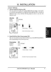
...) [2-3] JP1 1 2 3 Enable (Default) JP1 1 2 3 Disabled Multi I /O card. Programming Disabled Enabled JP2 [1-2] (Default) [2-3] JP2 123 Disabled (Default) JP2 123 Enabled Boot Block Programming (Disable / Enable) ASUS P/I-P55T2P4 User's Manual 7 INSTALLATION (Jumpers) III. INSTALLATION Jumper Settings 1. Flash ROM Boot Block Programming (JP2) This sets the operation mode of the boot block area of the BIOS...
...) [2-3] JP1 1 2 3 Enable (Default) JP1 1 2 3 Disabled Multi I /O card. Programming Disabled Enabled JP2 [1-2] (Default) [2-3] JP2 123 Disabled (Default) JP2 123 Enabled Boot Block Programming (Disable / Enable) ASUS P/I-P55T2P4 User's Manual 7 INSTALLATION (Jumpers) III. INSTALLATION Jumper Settings 1. Flash ROM Boot Block Programming (JP2) This sets the operation mode of the boot block area of the BIOS...

User Manual
Page 14
... jumper sets the total amount of L2 cache that is present onboard and installed as hard disk information and passwords. An "ASUS" or "COAST" cache module can be used to upgrade the 256KB version to re-enter user preferences. To clear the RTC... is present. Selections JP7 Operation [open] (Default) Clear Data [short] (momentarily) JP7 JP7 Operation (Default) Clear Data RTC RAM (Operation / Clear Data) 8 ASUS P/I-P55T2P4 User's Manual Selections JP5 256KB [1-2] 512KB [2-3] JP5 1 2 3 256KB JP5 1 2 3 512KB Total L2 Cache Size Setting (256KB / 512KB) 4. Real Time Clock (RTC...
... jumper sets the total amount of L2 cache that is present onboard and installed as hard disk information and passwords. An "ASUS" or "COAST" cache module can be used to upgrade the 256KB version to re-enter user preferences. To clear the RTC... is present. Selections JP7 Operation [open] (Default) Clear Data [short] (momentarily) JP7 JP7 Operation (Default) Clear Data RTC RAM (Operation / Clear Data) 8 ASUS P/I-P55T2P4 User's Manual Selections JP5 256KB [1-2] 512KB [2-3] JP5 1 2 3 256KB JP5 1 2 3 512KB Total L2 Cache Size Setting (256KB / 512KB) 4. Real Time Clock (RTC...
User Manual
Page 15
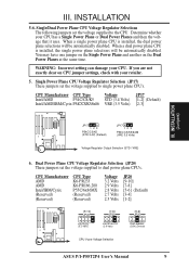
... 2.7 Volts 2.5 Volts JP20 [9-10] [7-8] [5-6] (Default) [3-4] [1-2] [9-10] JP20 K6-PR233 (3.2 Volts) [7-8] JP20 K6-PR166,200 (2.9 Volts) [5-6] JP20 P55C/6x86MX (2.8V) (Default) CPU Vcore Voltage Selection ASUS P/I-P55T2P4 User's Manual 9 Determine whether your CPU. Single Power Plane CPU Voltage Regulator Selection (JP17) These jumpers set the voltage supplied to dual power plane CPU's. Dual Power...
... 2.7 Volts 2.5 Volts JP20 [9-10] [7-8] [5-6] (Default) [3-4] [1-2] [9-10] JP20 K6-PR233 (3.2 Volts) [7-8] JP20 K6-PR166,200 (2.9 Volts) [5-6] JP20 P55C/6x86MX (2.8V) (Default) CPU Vcore Voltage Selection ASUS P/I-P55T2P4 User's Manual 9 Determine whether your CPU. Single Power Plane CPU Voltage Regulator Selection (JP17) These jumpers set the voltage supplied to dual power plane CPU's. Dual Power...

User Manual
Page 16
... generator what frequency to send to BUS Frequency Ratio (JP11, JP12) These jumpers set together with the Cyrix PR166+ installed on this motherboard. 10 ASUS P/I-P55T2P4 User's Manual These must be set the frequency ratio between the Internal frequency of the CPU and the External frequency (called the BUS Clock) within the CPU...
... generator what frequency to send to BUS Frequency Ratio (JP11, JP12) These jumpers set together with the Cyrix PR166+ installed on this motherboard. 10 ASUS P/I-P55T2P4 User's Manual These must be set the frequency ratio between the Internal frequency of the CPU and the External frequency (called the BUS Clock) within the CPU...

User Manual
Page 17
... The only Cyrix CPU that you need to install a TAG SRAM upgrade or use a cache module with an extended TAG SRAM (such as 256KB ASUS CM1 Rev 3.0 with 2 TAG SRAM's) but must be Revision 2.7 or later. WARNING: If there are DRAM cache chips (MCache) either onboard...JP4 [1-2] (Default) [2-3] JP4 123 64MB Cacheable (Default) Burst SRAM or MCache JP4 123 512MB Cacheable Burst SRAM Only Cacheable Size (64MB/512MB) ASUS P/I-P55T2P4 User's Manual 11 Memory Cacheable Size (JP4) The default of the CPU for cache module information. The number should read G8DC6620A or later. 9. Mcache chips can...
... The only Cyrix CPU that you need to install a TAG SRAM upgrade or use a cache module with an extended TAG SRAM (such as 256KB ASUS CM1 Rev 3.0 with 2 TAG SRAM's) but must be Revision 2.7 or later. WARNING: If there are DRAM cache chips (MCache) either onboard...JP4 [1-2] (Default) [2-3] JP4 123 64MB Cacheable (Default) Burst SRAM or MCache JP4 123 512MB Cacheable Burst SRAM Only Cacheable Size (64MB/512MB) ASUS P/I-P55T2P4 User's Manual 11 Memory Cacheable Size (JP4) The default of the CPU for cache module information. The number should read G8DC6620A or later. 9. Mcache chips can...

User Manual
Page 18
... will work minus the ECC feature. You must have an extended tag, do not install another TAG SRAM into the TAG SRAM Upgrade Socket. 12 ASUS P/I-P55T2P4 User's Manual
... will work minus the ECC feature. You must have an extended tag, do not install another TAG SRAM into the TAG SRAM Upgrade Socket. 12 ASUS P/I-P55T2P4 User's Manual
User Manual
Page 19
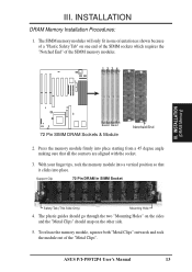
... Installation Procedures: 1. To release the memory module, squeeze both "Metal Clips" outwards and rock the module out of the SIMM memory modules. 1234 III. ASUS P/I-P55T2P4 User's Manual 13 The SIMM memory modules will only fit in SIMM Socket Safety Tab (This Side Only) Mounting Hole 4. With your finger tips, rock the memory...
... Installation Procedures: 1. To release the memory module, squeeze both "Metal Clips" outwards and rock the module out of the SIMM memory modules. 1234 III. ASUS P/I-P55T2P4 User's Manual 13 The SIMM memory modules will only fit in SIMM Socket Safety Tab (This Side Only) Mounting Hole 4. With your finger tips, rock the memory...

User Manual
Page 20
... install another TAG SRAM into the TAG SRAM Upgrade Socket. 14 ASUS P/I-P55T2P4 User's Manual An "ASUS" or "COAST" cache module can be upgraded any further. Compatible Cache Modules for this Motherboard SIMM Cache Module ASUS CM1 Rev 1.0 ASUS CM1 Rev 1.3 ASUS CM4 Rev 1.5 ASUS CM1 Rev 1.6 ASUS CM1 Rev 3.0 COAST 1.1 COAST 1.2 COAST 1.3 COAST 2.0 COAST 2.1 COAST 3.0 COAST 3.1 256KB to...
... install another TAG SRAM into the TAG SRAM Upgrade Socket. 14 ASUS P/I-P55T2P4 User's Manual An "ASUS" or "COAST" cache module can be upgraded any further. Compatible Cache Modules for this Motherboard SIMM Cache Module ASUS CM1 Rev 1.0 ASUS CM1 Rev 1.3 ASUS CM4 Rev 1.5 ASUS CM1 Rev 1.6 ASUS CM1 Rev 3.0 COAST 1.1 COAST 1.2 COAST 1.3 COAST 2.0 COAST 2.1 COAST 3.0 COAST 3.1 256KB to...


