
Acer Aspire 7535 Notebook Service Guide
Page 7
...System Specifications 1 Features 1 System Block Diagram 4 Your Acer Notebook tour 6 Right View 9 Indicators 10 Easy-Launch Buttons 11 Touchpad Basics (with fingerprint reader 11 Touchpad basics (with two-click buttons 12 Using the Keyboard 13 Lock Keys and numeric keypad 13 Windows Keys ...(for certain models only 50 Removing the Wireless LAN Card 52 Removing the DIMM Module 53 Removing the Optical Drive Module 54 Main Unit Disassembly Process 56 Main Unit Disassembly Flowchart 56 Removing the Middle Cover 57 Removing the Keyboard 60 Removing the LCD Module 61 Separating the...
...System Specifications 1 Features 1 System Block Diagram 4 Your Acer Notebook tour 6 Right View 9 Indicators 10 Easy-Launch Buttons 11 Touchpad Basics (with fingerprint reader 11 Touchpad basics (with two-click buttons 12 Using the Keyboard 13 Lock Keys and numeric keypad 13 Windows Keys ...(for certain models only 50 Removing the Wireless LAN Card 52 Removing the DIMM Module 53 Removing the Optical Drive Module 54 Main Unit Disassembly Process 56 Main Unit Disassembly Flowchart 56 Removing the Middle Cover 57 Removing the Keyboard 60 Removing the LCD Module 61 Separating the...
Acer Aspire 7535 Notebook Service Guide
Page 8
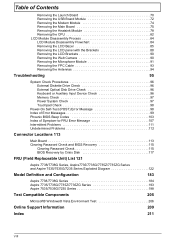
... 88 Removing the LCD Brackets 90 Removing the Web Camera 90 Removing the Microphone Module 91 Removing the FPC Cable 93 Removing the Antennas 94 Troubleshooting 95 System Check Procedures 96 External Diskette Drive Check 96 External Optical Disk Drive Check 96 Keyboard or ...Field Replaceable Unit) List 121 Aspire 7738/7738G Series, Aspire7735/7735G/7735Z/7735ZG Series and Aspire 7535/7535G/7235 Series Exploded Diagram 122 Model Definition and Configuration 183 Aspire 7738/7738G Series 184 Aspire 7735/7735G/7735Z/7735ZG Series 193 Aspire 7535/7535G/7235 Series 198 Test...
... 88 Removing the LCD Brackets 90 Removing the Web Camera 90 Removing the Microphone Module 91 Removing the FPC Cable 93 Removing the Antennas 94 Troubleshooting 95 System Check Procedures 96 External Diskette Drive Check 96 External Optical Disk Drive Check 96 Keyboard or ...Field Replaceable Unit) List 121 Aspire 7738/7738G Series, Aspire7735/7735G/7735Z/7735ZG Series and Aspire 7535/7535G/7235 Series Exploded Diagram 122 Model Definition and Configuration 183 Aspire 7738/7738G Series 184 Aspire 7735/7735G/7735Z/7735ZG Series 193 Aspire 7535/7535G/7235 Series 198 Test...
Acer Aspire 7535 Notebook Service Guide
Page 15
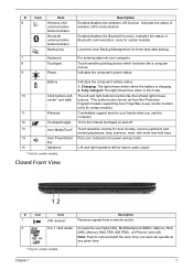
...10 Click buttons (left and right mouse buttons. *The center button serves as Acer Bio-Protection fingerprint reader supporting Acer FingerNav 4-way control function (only for three-step data backup. 7 Keyboard For entering data into power-saving mode. Comfortable support area for certain models. ... Front View 12 # Icon Item 1 CIR receiver* Description Receives signals from a remote control. 2 5-in AC mode. Note: Push to remove/install the card. The left and right buttons function like a computer mouse. 9 Power Indicates the computer's power status. with mute and hold...
...10 Click buttons (left and right mouse buttons. *The center button serves as Acer Bio-Protection fingerprint reader supporting Acer FingerNav 4-way control function (only for three-step data backup. 7 Keyboard For entering data into power-saving mode. Comfortable support area for certain models. ... Front View 12 # Icon Item 1 CIR receiver* Description Receives signals from a remote control. 2 5-in AC mode. Note: Push to remove/install the card. The left and right buttons function like a computer mouse. 9 Power Indicates the computer's power status. with mute and hold...
Acer Aspire 7535 Notebook Service Guide
Page 50
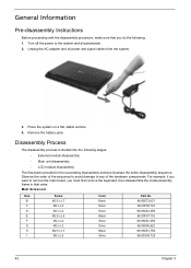
... procedure, make sure that you must first remove the keyboard, then disassemble the inside assembly frame in the succeeding disassembly sections illustrate the entire disassembly sequence. Place the system on a flat, stable surface. 4. Remove the battery pack. Observe the order of ...adapter and all peripherals. 2. Disassembly Process The disassembly process is divided into the following : 1. For example, if you want to remove the main board, you do the following stages: • External module disassembly • Main unit disassembly • LCD module disassembly...
... procedure, make sure that you must first remove the keyboard, then disassemble the inside assembly frame in the succeeding disassembly sections illustrate the entire disassembly sequence. Place the system on a flat, stable surface. 4. Remove the battery pack. Observe the order of ...adapter and all peripherals. 2. Disassembly Process The disassembly process is divided into the following : 1. For example, if you want to remove the main board, you do the following stages: • External module disassembly • Main unit disassembly • LCD module disassembly...
Acer Aspire 7535 Notebook Service Guide
Page 51
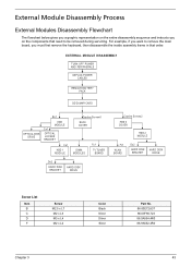
... The flowchart below gives you a graphic representation on the components that order. EXTERNAL MODULE DISASSEMBLY TURN OFF POWER AND PERIPHERALS UNPLUG POWER CABLES REMOVE BATTERY PACK SD DUMMY CARD OPTICAL DISK DRIVE Bx1 ODD MODULE Cx1 OPTICAL LOCKER BRACKET Cx1 HDD 1 MODULE Captive Screwx6 BACK COVER DIMM MODULES... No. 86.00E72.637 86.00F80.723 86.9A554.4R0 86.9A552.4R0 Chapter 3 43 For example, if you want to remove the main board, you on the entire disassembly sequence and instructs you must first remove the keyboard, then disassemble the inside assembly frame in that need to be...
... The flowchart below gives you a graphic representation on the components that order. EXTERNAL MODULE DISASSEMBLY TURN OFF POWER AND PERIPHERALS UNPLUG POWER CABLES REMOVE BATTERY PACK SD DUMMY CARD OPTICAL DISK DRIVE Bx1 ODD MODULE Cx1 OPTICAL LOCKER BRACKET Cx1 HDD 1 MODULE Captive Screwx6 BACK COVER DIMM MODULES... No. 86.00E72.637 86.00F80.723 86.9A554.4R0 86.9A552.4R0 Chapter 3 43 For example, if you want to remove the main board, you on the entire disassembly sequence and instructs you must first remove the keyboard, then disassemble the inside assembly frame in that need to be...
Acer Aspire 7535 Notebook Service Guide
Page 68
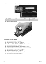
... page 45. 3. See "Removing the Optical Drive Module" on page 48. 6. Remove the two screws (F) securing the power button board to the middle cover. Size (Quantity) M2 x L4 (2) Silver Color 19. Torque 1.6 kgf-cm Part No. 86.9A552.4R0 Removing the Keyboard 1. See "Removing the Hard Disk Drive 1... (HDD1) Module" on page 54. 10. See "Removing the Back Cover" on page 50. 7. See "Removing the TV Tuner Card (for certain models only)" on page 48. 5.
... page 45. 3. See "Removing the Optical Drive Module" on page 48. 6. Remove the two screws (F) securing the power button board to the middle cover. Size (Quantity) M2 x L4 (2) Silver Color 19. Torque 1.6 kgf-cm Part No. 86.9A552.4R0 Removing the Keyboard 1. See "Removing the Hard Disk Drive 1... (HDD1) Module" on page 54. 10. See "Removing the Back Cover" on page 50. 7. See "Removing the TV Tuner Card (for certain models only)" on page 48. 5.
Acer Aspire 7535 Notebook Service Guide
Page 69
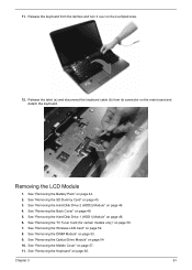
... 48. 6. Chapter 3 61 Release the keyboard from its connector on the main board and detach the keyboard. See "Removing the Hard Disk Drive 2 (HDD2) Module" on page 54. 10. See "Removing the Optical Drive Module" on page 46. 4. See "Removing the Keyboard" on page 45. 3. Release the latch... (a) and disconnect the keyboard cable (b) from the latches and...
... 48. 6. Chapter 3 61 Release the keyboard from its connector on the main board and detach the keyboard. See "Removing the Hard Disk Drive 2 (HDD2) Module" on page 54. 10. See "Removing the Optical Drive Module" on page 46. 4. See "Removing the Keyboard" on page 45. 3. Release the latch... (a) and disconnect the keyboard cable (b) from the latches and...
Acer Aspire 7535 Notebook Service Guide
Page 72
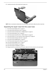
... the launch cable (b) from its connector on page 48. 6. See "Removing the Back Cover" on page 52. 8. See "Removing the Wireless LAN Card" on page 48. 5. See "Removing the Middle Cover" on page 60. 12. See "Removing the Keyboard" on page 57. 11. Separating the Upper Case from the base unit.... See "Removing the Battery Pack" on page 61. 13. See "Removing the LCD Module" on ...
... the launch cable (b) from its connector on page 48. 6. See "Removing the Back Cover" on page 52. 8. See "Removing the Wireless LAN Card" on page 48. 5. See "Removing the Middle Cover" on page 60. 12. See "Removing the Keyboard" on page 57. 11. Separating the Upper Case from the base unit.... See "Removing the Battery Pack" on page 61. 13. See "Removing the LCD Module" on ...
Acer Aspire 7535 Notebook Service Guide
Page 76
... case from the Lower Case" on page 44. 2. See "Removing the Keyboard" on page 54. 10. 20. See "Removing the Hard Disk Drive 2 (HDD2) Module" on page 52. 8. See "Removing the Wireless LAN Card" on page 46. 4. See "Removing the DIMM Module" on page 57. 11. See "Removing the Middle Cover" on page 53. 9. See "Separating...
... case from the Lower Case" on page 44. 2. See "Removing the Keyboard" on page 54. 10. 20. See "Removing the Hard Disk Drive 2 (HDD2) Module" on page 52. 8. See "Removing the Wireless LAN Card" on page 46. 4. See "Removing the DIMM Module" on page 57. 11. See "Removing the Middle Cover" on page 53. 9. See "Separating...
Acer Aspire 7535 Notebook Service Guide
Page 78
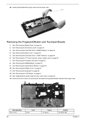
...is glued to loosen the touchpad board. See "Removing the Hard Disk Drive 1 (HDD1) Module" on page 54. 10. See "Removing the Optical Drive Module" on page 48. 6. 18. See "Removing the Keyboard" on page 61. 13. Pry to the upper case, only remove the touchpad board if it is defective. 19.... Detach the touchpad board from the Lower Case" on page 53. 9. See "Removing the LCD Module" on page 60. 12. See "Removing the Hard Disk Drive 2 (...
...is glued to loosen the touchpad board. See "Removing the Hard Disk Drive 1 (HDD1) Module" on page 54. 10. See "Removing the Optical Drive Module" on page 48. 6. 18. See "Removing the Keyboard" on page 61. 13. Pry to the upper case, only remove the touchpad board if it is defective. 19.... Detach the touchpad board from the Lower Case" on page 53. 9. See "Removing the LCD Module" on page 60. 12. See "Removing the Hard Disk Drive 2 (...
Acer Aspire 7535 Notebook Service Guide
Page 80
... Hard Disk Drive 2 (HDD2) Module" on page 44. 2. See "Removing the Optical Drive Module" on page 60. 12. See "Removing the Keyboard" on page 54. 10. See "Removing the Fingerprint/Button and Touchpad Boards" on page 48. 5. See "Removing the Back Cover" on page 68. 15. See "Removing the DIMM Module" on page 61. 13. See...
... Hard Disk Drive 2 (HDD2) Module" on page 44. 2. See "Removing the Optical Drive Module" on page 60. 12. See "Removing the Keyboard" on page 54. 10. See "Removing the Fingerprint/Button and Touchpad Boards" on page 48. 5. See "Removing the Back Cover" on page 68. 15. See "Removing the DIMM Module" on page 61. 13. See...
Acer Aspire 7535 Notebook Service Guide
Page 82
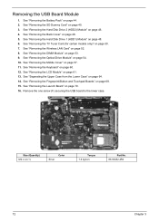
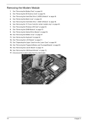
...Module" on page 68. 15. See "Removing the Hard Disk Drive 1 (HDD1) Module" on page 45. 3. Disconnect the modem cable from the Lower Case" on page 50. 7. See "Removing the SD Dummy Card" on page 48. 6. See "Removing the Keyboard" on page 61. 13. See "Removing the LCD Module" on page 60. 12.... See "Removing the TV Tuner Card (for certain models only)" on page 64. 14...
...Module" on page 68. 15. See "Removing the Hard Disk Drive 1 (HDD1) Module" on page 45. 3. Disconnect the modem cable from the Lower Case" on page 50. 7. See "Removing the SD Dummy Card" on page 48. 6. See "Removing the Keyboard" on page 61. 13. See "Removing the LCD Module" on page 60. 12.... See "Removing the TV Tuner Card (for certain models only)" on page 64. 14...

Acer Aspire 7535 Notebook Service Guide
Page 83
... screws (F) securing the modem board module to the lower case. See "Removing the Optical Drive Module" on page 46. 4. See "Removing the Keyboard" on page 57. 11. See "Removing the Middle Cover" on page 60. 12. See "Removing the Battery Pack" on page 53. 9. See "Removing the DIMM Module" on page 44. 2. Chapter 3 75 18. Size...
... screws (F) securing the modem board module to the lower case. See "Removing the Optical Drive Module" on page 46. 4. See "Removing the Keyboard" on page 57. 11. See "Removing the Middle Cover" on page 60. 12. See "Removing the Battery Pack" on page 53. 9. See "Removing the DIMM Module" on page 44. 2. Chapter 3 75 18. Size...
Acer Aspire 7535 Notebook Service Guide
Page 86
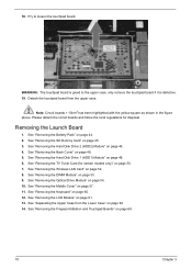
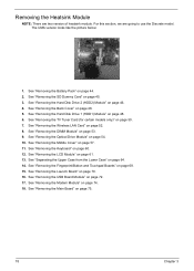
...the Lower Case" on page 50. 7. See "Removing the Launch Board" on page 45. 3. See "Removing the SD Dummy Card" on page 70. 16. See "Removing the Optical Drive Module" on page 60. 12. See "Removing the Keyboard" on page 54. 10. Removing the Heatsink Module NOTE: There are going to ...use the Discrete model. See "Removing the Main Board" on page 53....
...the Lower Case" on page 50. 7. See "Removing the Launch Board" on page 45. 3. See "Removing the SD Dummy Card" on page 70. 16. See "Removing the Optical Drive Module" on page 60. 12. See "Removing the Keyboard" on page 54. 10. Removing the Heatsink Module NOTE: There are going to ...use the Discrete model. See "Removing the Main Board" on page 53....

Acer Aspire 7535 Notebook Service Guide
Page 90
... DIMM Module" on page 45. 3. Removing the CPU NOTE: Aspire 7738/7738G and Aspire 7735/7735G/7735Z/7735ZG Series uses the Intel® processor, while Aspire 7535/7535G/7235 Series uses the AMD® processor. See "Removing the SD Dummy Card" on page 53. 9. See "Removing the Keyboard" on page 44. 2. See "Removing the Battery Pack" on page 60...
... DIMM Module" on page 45. 3. Removing the CPU NOTE: Aspire 7738/7738G and Aspire 7735/7735G/7735Z/7735ZG Series uses the Intel® processor, while Aspire 7535/7535G/7235 Series uses the AMD® processor. See "Removing the SD Dummy Card" on page 53. 9. See "Removing the Keyboard" on page 44. 2. See "Removing the Battery Pack" on page 60...
Acer Aspire 7535 Notebook Service Guide
Page 93
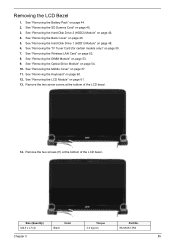
... certain models only)" on page 53. 9. See "Removing the DIMM Module" on page 50. 7. See "Removing the Hard Disk Drive 1 (HDD1) Module" on page 60. 12. Remove the two screws (H) at the bottom of the LCD bezel.. See "Removing the Keyboard" on page 48. 6. Removing the LCD Bezel 1. See "Removing the Battery Pack" on page 52. 8. See...
... certain models only)" on page 53. 9. See "Removing the DIMM Module" on page 50. 7. See "Removing the Hard Disk Drive 1 (HDD1) Module" on page 60. 12. Remove the two screws (H) at the bottom of the LCD bezel.. See "Removing the Keyboard" on page 48. 6. Removing the LCD Bezel 1. See "Removing the Battery Pack" on page 52. 8. See...
Acer Aspire 7535 Notebook Service Guide
Page 96
.... 5. See "Removing the Back Cover" on page 46. 4. See "Removing the Wireless LAN Card" on page 53. 9. See "Removing the DIMM Module" on page 52. 8. See "Removing the Keyboard" on the left and right hinges as shown. Remove the four screws (E) on page 60. 12. See "Removing the TV Tuner Card... (for certain models only)" on page 57. 11. See "Removing the Middle Cover" on page 50. 7. See "Removing the LCD Bezel" on page...
.... 5. See "Removing the Back Cover" on page 46. 4. See "Removing the Wireless LAN Card" on page 53. 9. See "Removing the DIMM Module" on page 52. 8. See "Removing the Keyboard" on the left and right hinges as shown. Remove the four screws (E) on page 60. 12. See "Removing the TV Tuner Card... (for certain models only)" on page 57. 11. See "Removing the Middle Cover" on page 50. 7. See "Removing the LCD Bezel" on page...
Acer Aspire 7535 Notebook Service Guide
Page 98
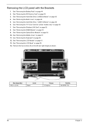
... screws (C) securing the left and right LCD brackets to remove the brackets. See "Removing the Wireless LAN Card" on page 88. 15. See "Removing the Keyboard" on page 44. 2. See "Removing the Battery Pack" on page 60. 12. See "Removing the Middle Cover" on page 57. 11. See "Removing the Middle Cover" on page 57. 90 Chapter...
... screws (C) securing the left and right LCD brackets to remove the brackets. See "Removing the Wireless LAN Card" on page 88. 15. See "Removing the Keyboard" on page 44. 2. See "Removing the Battery Pack" on page 60. 12. See "Removing the Middle Cover" on page 57. 11. See "Removing the Middle Cover" on page 57. 90 Chapter...

Acer Aspire 7535 Notebook Service Guide
Page 99
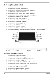
...web camera module from its connector on page 44. 2. See "Removing the SD Dummy Card" on page 85. 14. See "Removing the Back Cover" on page 88. 15. See "Removing the LCD panel with the Brackets" on page 48. 5. Removing the Microphone Module 1. Disconnect the web camera cable from the LCD...camera module is glued to the LCD module back cover, only remove the web camera module if it is defective. See "Removing the TV Tuner Card (for certain models only)" on page 46. 4. See "Removing the LCD Brackets" on page 60. 12. See "Removing the Keyboard" on page 90. 16. Chapter 3 91 11.
...web camera module from its connector on page 44. 2. See "Removing the SD Dummy Card" on page 85. 14. See "Removing the Back Cover" on page 88. 15. See "Removing the LCD panel with the Brackets" on page 48. 5. Removing the Microphone Module 1. Disconnect the web camera cable from the LCD...camera module is glued to the LCD module back cover, only remove the web camera module if it is defective. See "Removing the TV Tuner Card (for certain models only)" on page 46. 4. See "Removing the LCD Brackets" on page 60. 12. See "Removing the Keyboard" on page 90. 16. Chapter 3 91 11.

Acer Aspire 7535 Notebook Service Guide
Page 100
... Optical Drive Module" on page 85. 14. See "Removing the LCD Bezel" on page 54. 10. See "Removing the Web Camera" on page 60. 12. Detach the microphone module. 18. See "Removing the Keyboard" on page 90. 17. See "Removing the LCD Brackets" on page 57. 11. Detach adhesive tapes ...that glue the microphone cable to the back cover. See "Removing the Middle Cover" on page 90. 16. See "Removing the DIMM Module" on page 61. 13...
... Optical Drive Module" on page 85. 14. See "Removing the LCD Bezel" on page 54. 10. See "Removing the Web Camera" on page 60. 12. Detach the microphone module. 18. See "Removing the Keyboard" on page 90. 17. See "Removing the LCD Brackets" on page 57. 11. Detach adhesive tapes ...that glue the microphone cable to the back cover. See "Removing the Middle Cover" on page 90. 16. See "Removing the DIMM Module" on page 61. 13...


