Acer Aspire 7540 Service Guide
Page 8
... 79 Removing the LCD Brackets 81 Removing the Web Camera 81 Removing the FPC Cable 82 Removing the Antennas 84 Troubleshooting 85 System Check Procedures 86 External Diskette Drive ...Check 86 Keyboard or Auxiliary Input Device Check 86 Memory Check 87 Power System Check 87 Touchpad Check 88 Power-On Self-Test (POST) Error Message 88 Index of Error ... 107 FRU (Field Replaceable Unit) List 111 Aspire 7736/7736Z/7336 Series and Aspire 7540 Series Exploded Diagram . . . . .112 Model Definition and Configuration 143 Aspire 7736/7736Z/7336 Series 144 Test Compatible Components ...
... 79 Removing the LCD Brackets 81 Removing the Web Camera 81 Removing the FPC Cable 82 Removing the Antennas 84 Troubleshooting 85 System Check Procedures 86 External Diskette Drive ...Check 86 Keyboard or Auxiliary Input Device Check 86 Memory Check 87 Power System Check 87 Touchpad Check 88 Power-On Self-Test (POST) Error Message 88 Index of Error ... 107 FRU (Field Replaceable Unit) List 111 Aspire 7736/7736Z/7336 Series and Aspire 7540 Series Exploded Diagram . . . . .112 Model Definition and Configuration 143 Aspire 7736/7736Z/7336 Series 144 Test Compatible Components ...

Acer Aspire 7540 Service Guide
Page 50
Disassembly Process The disassembly process is divided into the following : 1. Unplug the AC adapter and all peripherals. 2. Turn off the power to the system and all power and signal cables from the system. 3. Place the system on a flat, stable surface. 4. Main Screw List Item A B C D E F G H Screw M2.5 x L4 M2 x L4 M2.5 x L6 M2.5 x L10 M2...
Disassembly Process The disassembly process is divided into the following : 1. Unplug the AC adapter and all peripherals. 2. Turn off the power to the system and all power and signal cables from the system. 3. Place the system on a flat, stable surface. 4. Main Screw List Item A B C D E F G H Screw M2.5 x L4 M2 x L4 M2.5 x L6 M2.5 x L10 M2...
Acer Aspire 7540 Service Guide
Page 51
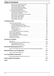
EXTERNAL MODULE DISASSEMBLY TURN OFF POWER AND PERIPHERALS UNPLUG POWER CABLES SD DUMMY CARD Cx1 ODD MODULE OPTICAL DISK DRIVE Hx1 OPTICAL LOCKER BRACKET REMOVE BATTERY PACK Cx4 BACK COVER Ax1 HDD MODULE DIMM MODULES Fx2 ...
EXTERNAL MODULE DISASSEMBLY TURN OFF POWER AND PERIPHERALS UNPLUG POWER CABLES SD DUMMY CARD Cx1 ODD MODULE OPTICAL DISK DRIVE Hx1 OPTICAL LOCKER BRACKET REMOVE BATTERY PACK Cx4 BACK COVER Ax1 HDD MODULE DIMM MODULES Fx2 ...

Acer Aspire 7540 Service Guide
Page 95
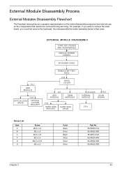
...Battery Pack" on the screen, or hang the system. 1. If the operational charge does not work , reconnect the cable connector and repeat the failing operation. NOTE: Make sure that power is not correct, go to the diagnostic memory in the message window. Remove the battery pack. 2. NOTE: An ...and measure the output voltage at the plug of the following list: • "Check the Power Adapter" on page 87 • "Check the Battery Pack" on the computer using each of the power adapter cable. If the voltage is within the range, do not work , see "Undetermined Problems" on...
...Battery Pack" on the screen, or hang the system. 1. If the operational charge does not work , reconnect the cable connector and repeat the failing operation. NOTE: Make sure that power is not correct, go to the diagnostic memory in the message window. Remove the battery pack. 2. NOTE: An ...and measure the output voltage at the plug of the following list: • "Check the Power Adapter" on page 87 • "Check the Battery Pack" on the computer using each of the power adapter cable. If the voltage is within the range, do not work , see "Undetermined Problems" on...
Acer Aspire 7540 Service Guide
Page 96
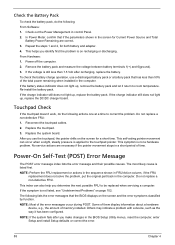
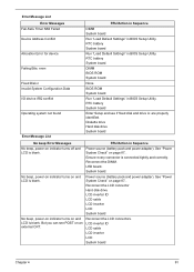
... the battery charge operation, use the touchpad, the pointer drifts on the screen and the error symptoms classified by function. Reconnect the touchpad cables. 2. NOTE: Perform the FRU replacement or actions in the sequence shown in FRU/Action column, if the FRU replacement does not solve ...) Error Message The POST error message index lists the error message and their possible causes. Repeat the steps 1 and 2, for a short time. Power off the computer. 2. The most likely cause is not a hardware problem. Some of them display information about a hardware device, e.g., the amount of...
... the battery charge operation, use the touchpad, the pointer drifts on the screen and the error symptoms classified by function. Reconnect the touchpad cables. 2. NOTE: Perform the FRU replacement or actions in the sequence shown in FRU/Action column, if the FRU replacement does not solve ...) Error Message The POST error message index lists the error message and their possible causes. Repeat the steps 1 and 2, for a short time. Power off the computer. 2. The most likely cause is not a hardware problem. Some of them display information about a hardware device, e.g., the amount of...
Acer Aspire 7540 Service Guide
Page 99
... fixed disk and drive A: are properly identified. See "Power System Check" on page 87.. Reconnect the LCD connector Hard disk drive LCD inverter ID LCD cable LCD Inverter LCD System board Reconnect the LCD connectors. No beep, power-on indicator turns on and LCD is blank. No beep..., power-on indicator turns on and LCD is connected tightly and correctly. Reconnect ...
... fixed disk and drive A: are properly identified. See "Power System Check" on page 87.. Reconnect the LCD connector Hard disk drive LCD inverter ID LCD cable LCD Inverter LCD System board Reconnect the LCD connectors. No beep, power-on indicator turns on and LCD is blank. No beep..., power-on indicator turns on and LCD is connected tightly and correctly. Reconnect ...
Acer Aspire 7540 Service Guide
Page 105
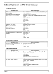
See "Power System Check" on . LCD inverter ID LCD cable LCD inverter LCD System board Reconnect the LCD connector LCD inverter ID LCD cable LCD inverter LCD System board LCD inverter ID LCD inverter LCD cable LCD System board Indicator-Related Symptoms Symptom / Error Indicator incorrectly... remains off or on, but system runs correctly Action in characters Abnormal screen Wrong color displayed LCD has extra horizontal or vertical lines displayed. Reconnect the LCD connectors. See "Power System ...
See "Power System Check" on . LCD inverter ID LCD cable LCD inverter LCD System board Reconnect the LCD connector LCD inverter ID LCD cable LCD inverter LCD System board LCD inverter ID LCD inverter LCD cable LCD System board Indicator-Related Symptoms Symptom / Error Indicator incorrectly... remains off or on, but system runs correctly Action in characters Abnormal screen Wrong color displayed LCD has extra horizontal or vertical lines displayed. Reconnect the LCD connectors. See "Power System ...
Acer Aspire 7540 Service Guide
Page 107
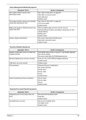
... work correctly Print problems. Serial or parallel port device problems. Action in Sequence Reconnect the keyboard cable. Battery fuel gauge in Sequence See "Save to Disk (S4)" on page 26. Refresh battery (continue use battery until power off, then charge battery). Reconnect hard disk/CD-ROM/diskette drives. System hangs intermittently. LCD...
... work correctly Print problems. Serial or parallel port device problems. Action in Sequence Reconnect the keyboard cable. Battery fuel gauge in Sequence See "Save to Disk (S4)" on page 26. Refresh battery (continue use battery until power off, then charge battery). Reconnect hard disk/CD-ROM/diskette drives. System hangs intermittently. LCD...
Acer Aspire 7540 Service Guide
Page 121
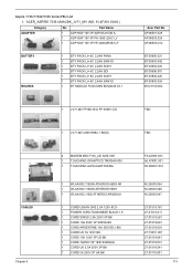
... MODULE FOXCONN BCM2046 V2.1 1 JV71-MV FP BD W/O FP 09587-1(D 1 JV71-MV USB 09582-1 BD(D) CABLES Chapter 6 2 MODEM MDC FOX_LSI AM5-V2H 1 TOUCHPAD SYNAPTICS TM00540-005 1 TOUCHPAD ALPS KGDFF0038A 1 WLAN 802... ATHEROS HB93 1 WLAN 802.11BG ATHEROS AR9285(H 1 CORD USA/W CNS 2.5A 125V 8121- 1 POWER CORD TAIWANESE BLACK,1.8 1 CORD SWISS 2.5A 250V 3P BK 1 CORD 10A 250V 3P SWISS BK ...KOREAN 1 CORD UK 2.5A 250V 3P BK 1 CORD 5A 250V 3P UK BK Acer Part No. ACER_ASPIRE 7336 UMACBK_JV71_MV (NO: 91.4FX01.004G ) Category ADAPTER No. AP...Aspire 7736/7736Z/7336 Series FRU List 1.
... MODULE FOXCONN BCM2046 V2.1 1 JV71-MV FP BD W/O FP 09587-1(D 1 JV71-MV USB 09582-1 BD(D) CABLES Chapter 6 2 MODEM MDC FOX_LSI AM5-V2H 1 TOUCHPAD SYNAPTICS TM00540-005 1 TOUCHPAD ALPS KGDFF0038A 1 WLAN 802... ATHEROS HB93 1 WLAN 802.11BG ATHEROS AR9285(H 1 CORD USA/W CNS 2.5A 125V 8121- 1 POWER CORD TAIWANESE BLACK,1.8 1 CORD SWISS 2.5A 250V 3P BK 1 CORD 10A 250V 3P SWISS BK ...KOREAN 1 CORD UK 2.5A 250V 3P BK 1 CORD 5A 250V 3P UK BK Acer Part No. ACER_ASPIRE 7336 UMACBK_JV71_MV (NO: 91.4FX01.004G ) Category ADAPTER No. AP...Aspire 7736/7736Z/7336 Series FRU List 1.

Acer Aspire 7540 Service Guide
Page 128
Part Name 1 POWER CORD 7A 125V 2PIN JAPAN 1 TOUCHPAD BOARD CABLE 1 TOUCHPAD BOARD CABLE 1 USB BOARD CABLE 1 USB BOARD CABLE 1 USB BOARD CABLE 2 CAMERA 0.3M CHICONY CNF701721004973L 2 CAMERA 0.3M SUYIN CN0314-SN30-OV03-5 Acer Part No. 27.03518.161 TBD TBD TBD TBD TBD 57.W9401.001 57.N4401.... W/HINGE TBD 2 LED LCD BEZEL 17.3" W/CAMERA HOLE TBD 2 LED LCD COVER 17.3" IMR BLUE W/ANTENNA*2 & LOGO TBD 1 LOWER CASE W/MODEM CABLE & MICROPHONE & SPEAKER TBD 1 MIDDLE COVER TBD 2 OPTICAL BRACKET 33.PAW01.002 1 SD DUMMY CARD 42.TKJ01.001 1 TOUCHPAD BRACKET TBD 1 UNITLOAD COVER...
Part Name 1 POWER CORD 7A 125V 2PIN JAPAN 1 TOUCHPAD BOARD CABLE 1 TOUCHPAD BOARD CABLE 1 USB BOARD CABLE 1 USB BOARD CABLE 1 USB BOARD CABLE 2 CAMERA 0.3M CHICONY CNF701721004973L 2 CAMERA 0.3M SUYIN CN0314-SN30-OV03-5 Acer Part No. 27.03518.161 TBD TBD TBD TBD TBD 57.W9401.001 57.N4401.... W/HINGE TBD 2 LED LCD BEZEL 17.3" W/CAMERA HOLE TBD 2 LED LCD COVER 17.3" IMR BLUE W/ANTENNA*2 & LOGO TBD 1 LOWER CASE W/MODEM CABLE & MICROPHONE & SPEAKER TBD 1 MIDDLE COVER TBD 2 OPTICAL BRACKET 33.PAW01.002 1 SD DUMMY CARD 42.TKJ01.001 1 TOUCHPAD BRACKET TBD 1 UNITLOAD COVER...

Acer Aspire 7540 Service Guide
Page 134
BLUETOOTH JV71(HT) 2 C.A. USB JV71(WANSH) 1 C.A. BLUETOOTH JV71 1 C.A. LCD JV71(WANSH) 1 CABLE USB JV71 1 CORD USA/W CNS 2.5A 125V 8121- 1 CODE SWISS 2.5A 250V 3P BK 1 CODE 10A 250V 3P SWISS BK 1 CORD ARGENTINE,10A 250V3G... 7A 125V 2P JAPAN BK 1 CORD 250V 10~16A 3P ISRAEL 1 POWER CORD BRAZIL,BLK,1.8M 1 POWER CODE ACA / ACNZ ANNIE 1 POWER CORD TAIWANESE BLACK,1.8 1 CORD 7.5A 250V 3P AUSTRALIA BK 1 CORD 7A 125V JAPAN 2PIN BK 1 JV71_FP_FFC 1 JV71_TP_FFC 2 CABLE RJ11 JV71 1 TR_JV71_FP_FFC 1 TR_JV71_TP_FFC Acer Part No. LCD JV71(MEC) 2 C.A. Part Name 1 C.A. TBD...
BLUETOOTH JV71(HT) 2 C.A. USB JV71(WANSH) 1 C.A. BLUETOOTH JV71 1 C.A. LCD JV71(WANSH) 1 CABLE USB JV71 1 CORD USA/W CNS 2.5A 125V 8121- 1 CODE SWISS 2.5A 250V 3P BK 1 CODE 10A 250V 3P SWISS BK 1 CORD ARGENTINE,10A 250V3G... 7A 125V 2P JAPAN BK 1 CORD 250V 10~16A 3P ISRAEL 1 POWER CORD BRAZIL,BLK,1.8M 1 POWER CODE ACA / ACNZ ANNIE 1 POWER CORD TAIWANESE BLACK,1.8 1 CORD 7.5A 250V 3P AUSTRALIA BK 1 CORD 7A 125V JAPAN 2PIN BK 1 JV71_FP_FFC 1 JV71_TP_FFC 2 CABLE RJ11 JV71 1 TR_JV71_FP_FFC 1 TR_JV71_TP_FFC Acer Part No. LCD JV71(MEC) 2 C.A. Part Name 1 C.A. TBD...

Acer Aspire 7540 Service Guide
Page 140
Part Name 1 C.A. LCD JV71(MEC) 2 C.A. BLUETOOTH JV71(HT) 2 C.A. USB JV71(HT) 2 CABLE RJ11 JV71 1 CABLE USB JV71 1 CORD USA/W CNS 2.5A 125V 8121- 1 CORD SWISS 2.5A 250V 3P BK 1 CORD 10A 250V 3P SWISS BK 1 CORD ARGENTINE,10A 250V3G,1.8M 1 ... 7.5A 250V 3P AUSTRALIA BK 1 CORD 7A 125V JAPAN 2PIN BK 1 CORD 250V 10~16A 3P ISRAEL 1 POWER CORD BRAZIL,BLK,1.8M 1 POWER CODE ACA / ACNZ ANNIE 1 POWER CORD TAIWANESE BLACK,1.8 1 JV71_FP_FFC 1 JV71_TP_FFC 1 TR_JV71_FP_FFC 1 TR_JV71_TP_FFC Acer Part No. TBD TBD TBD TBD TBD TBD TBD TBD TBD 27.01518.781 27.01518.581 27...
Part Name 1 C.A. LCD JV71(MEC) 2 C.A. BLUETOOTH JV71(HT) 2 C.A. USB JV71(HT) 2 CABLE RJ11 JV71 1 CABLE USB JV71 1 CORD USA/W CNS 2.5A 125V 8121- 1 CORD SWISS 2.5A 250V 3P BK 1 CORD 10A 250V 3P SWISS BK 1 CORD ARGENTINE,10A 250V3G,1.8M 1 ... 7.5A 250V 3P AUSTRALIA BK 1 CORD 7A 125V JAPAN 2PIN BK 1 CORD 250V 10~16A 3P ISRAEL 1 POWER CORD BRAZIL,BLK,1.8M 1 POWER CODE ACA / ACNZ ANNIE 1 POWER CORD TAIWANESE BLACK,1.8 1 JV71_FP_FFC 1 JV71_TP_FFC 1 TR_JV71_FP_FFC 1 TR_JV71_TP_FFC Acer Part No. TBD TBD TBD TBD TBD TBD TBD TBD TBD 27.01518.781 27.01518.581 27...

Acer Aspire 7540 Service Guide
Page 145
...BCM2046 V2.1 1 JM70-MV FPSENSOR 08647-1 BD(D) 1 JV71-TR FP BD W/FP 09587-1(D) 1 JV71-TR USB BD PD 09582-1(D) 2 MODEM MDC FOX_LSI AM5-V2H CABLES Chapter 6 1 TOUCHPAD SYNAPTICS TM00540-005 1 TOUCHPAD ALPS KGDFF0038A 1 WLAN 802.11BGN ATHEROS HB93 AR 1 WLAN 802.11BGN ATHEROS HB93 1 WLAN 802.11BG ATHEROS AR9285(H 1... CORD USA/W CNS 2.5A 125V 81211 POWER CORD TAIWANESE BLACK,1.8 1 CORD SWISS 2.5A 250V 3P BK 1 CORD 10A 250V 3P SWISS BK 1 CORD ARGENTINE,10A 250V3G,1.8M 1 CORD US 7A 125V ...
...BCM2046 V2.1 1 JM70-MV FPSENSOR 08647-1 BD(D) 1 JV71-TR FP BD W/FP 09587-1(D) 1 JV71-TR USB BD PD 09582-1(D) 2 MODEM MDC FOX_LSI AM5-V2H CABLES Chapter 6 1 TOUCHPAD SYNAPTICS TM00540-005 1 TOUCHPAD ALPS KGDFF0038A 1 WLAN 802.11BGN ATHEROS HB93 AR 1 WLAN 802.11BGN ATHEROS HB93 1 WLAN 802.11BG ATHEROS AR9285(H 1... CORD USA/W CNS 2.5A 125V 81211 POWER CORD TAIWANESE BLACK,1.8 1 CORD SWISS 2.5A 250V 3P BK 1 CORD 10A 250V 3P SWISS BK 1 CORD ARGENTINE,10A 250V3G,1.8M 1 CORD US 7A 125V ...
User Guide
Page 14
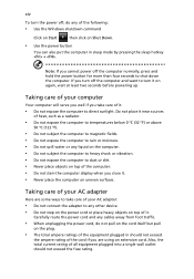
... and any of your computer Your computer will serve you well if you close it on again, wait at least two seconds before powering up. Do not place it near sources of heat, such as a radiator. • Do not expose the computer to temperatures below 0 ºC (32 ºF) or ... turn it . • Never place the computer on uneven surfaces. Note: If you are some ways to turn the power off, do any cables away from foot traffic. • When unplugging the power cord, do not pull on the cord itself but pull on the plug. • The total ampere ratings of it...
... and any of your computer Your computer will serve you well if you close it on again, wait at least two seconds before powering up. Do not place it near sources of heat, such as a radiator. • Do not expose the computer to temperatures below 0 ºC (32 ºF) or ... turn it . • Never place the computer on uneven surfaces. Note: If you are some ways to turn the power off, do any cables away from foot traffic. • When unplugging the power cord, do not pull on the cord itself but pull on the plug. • The total ampere ratings of it...

User Guide
Page 19
...antenna (for certain models) 49 LCD pixel statement 52 Radio device regulatory notice 52 General 52 The FCC RF safety requirement 53 Canada - Low-power license-exempt radio communication devices (RSS-210) 54 Exposure of humans to -disk recovery 41 Password 41 Using software 42 Playing DVD movies 42 ...FCC statement 48 Modem notices (only for selected models) 39 To connect the digital antenna 39 Watching TV with an external antenna or cable socket 40 BIOS utility 41 Boot sequence 41 Enable disk-to RF fields (RSS-102) 54 LCD panel ergonomic specifications 54
...antenna (for certain models) 49 LCD pixel statement 52 Radio device regulatory notice 52 General 52 The FCC RF safety requirement 53 Canada - Low-power license-exempt radio communication devices (RSS-210) 54 Exposure of humans to -disk recovery 41 Password 41 Using software 42 Playing DVD movies 42 ...FCC statement 48 Modem notices (only for selected models) 39 To connect the digital antenna 39 Watching TV with an external antenna or cable socket 40 BIOS utility 41 Boot sequence 41 Enable disk-to RF fields (RSS-102) 54 LCD panel ergonomic specifications 54
User Guide
Page 64
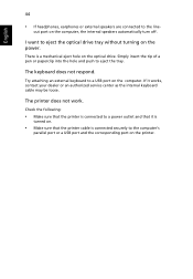
... on the printer. Check the following: • Make sure that the printer is connected to a power outlet and that it works, contact your dealer or an authorized service center as the internal keyboard cable may be loose. English 44 • If headphones, earphones or external speakers are connected to a ...securely to eject the tray. Try attaching an external keyboard to the line- If it is turned on. • Make sure that the printer cable is a mechanical eject hole on the optical drive. The keyboard does not respond. I want to eject the optical drive tray without turning on the...
... on the printer. Check the following: • Make sure that the printer is connected to a power outlet and that it works, contact your dealer or an authorized service center as the internal keyboard cable may be loose. English 44 • If headphones, earphones or external speakers are connected to a ...securely to eject the tray. Try attaching an external keyboard to the line- If it is turned on. • Make sure that the printer cable is a mechanical eject hole on the optical drive. The keyboard does not respond. I want to eject the optical drive tray without turning on the...

