Quick Start Guide
Page 5
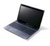
... on such subjects as system utilities, data recovery, expansion options and troubleshooting. If Adobe Reader is available in the text with setting up your computer can help you use Adobe Reader, access the Help and Support menu. Follow the instructions on how to complete the installation. For instructions on the screen to use your Acer notebook, we have designed a set of guides: First off, the setup poster helps you purchased. Please...
... on such subjects as system utilities, data recovery, expansion options and troubleshooting. If Adobe Reader is available in the text with setting up your computer can help you use Adobe Reader, access the Help and Support menu. Follow the instructions on how to complete the installation. For instructions on the screen to use your Acer notebook, we have designed a set of guides: First off, the setup poster helps you purchased. Please...
Quick Start Guide
Page 7
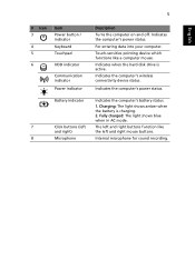
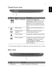
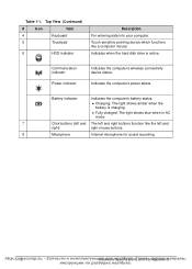
... power status. Fully charged: The light shows blue when in AC mode. 7 Click buttons (left The left and right mouse buttons. 8 Microphone Internal microphone for sound recording. Indicates when the hard disk drive is charging. 2. Battery indicator Indicates the computer's battery status. 1. Charging: The light shows amber when the battery is active. 5 English # Icon 3 4 5 Item Power button / indicator Keyboard Touchpad 6 HDD indicator Communication indicator Power indicator Description Turns the computer on and off. Touch-sensitive pointing device which functions...
... power status. Fully charged: The light shows blue when in AC mode. 7 Click buttons (left The left and right mouse buttons. 8 Microphone Internal microphone for sound recording. Indicates when the hard disk drive is charging. 2. Battery indicator Indicates the computer's battery status. 1. Charging: The light shows amber when the battery is active. 5 English # Icon 3 4 5 Item Power button / indicator Keyboard Touchpad 6 HDD indicator Communication indicator Power indicator Description Turns the computer on and off. Touch-sensitive pointing device which functions...
Quick Start Guide
Page 8
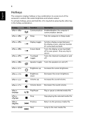
...Switches display output between the display screen, external monitor (if connected) and both. Speaker toggle Turns the speakers on and off . + < > + < > + < > + < > + + + + Brightness up Decreases the screen brightness. Increases the sound volume. Sleep Puts the computer in the hotkey combination. Turns the internal touchpad on and off . Volume down Volume up Increases the screen brightness. Next Jump to save power. Previous Return to access most of the computer's controls like screen brightness and volume output. Hotkey Icon + + Function...
...Switches display output between the display screen, external monitor (if connected) and both. Speaker toggle Turns the speakers on and off . + < > + < > + < > + < > + + + + Brightness up Decreases the screen brightness. Increases the sound volume. Sleep Puts the computer in the hotkey combination. Turns the internal touchpad on and off . Volume down Volume up Increases the screen brightness. Next Jump to save power. Previous Return to access most of the computer's controls like screen brightness and volume output. Hotkey Icon + + Function...
Quick Start Guide
Page 9
...'s battery status. 1. Fully charged: The light shows blue when in -1 card reader Accepts Secure Digital (SD), MultiMediaCard (MMC), Memory Stick PRO (MS PRO), xD-Picture Card (xD). Note: Push to remove/install the card. The front panel indicators are visible even when the computer cover is charging. 2. Charging: The light shows amber when the battery is closed. Rear view # Item 1 Battery bay 1 Description Houses the computer's battery pack. HDD indicator Indicates when the hard disk drive is active. Power indicator Indicates...
...'s battery status. 1. Fully charged: The light shows blue when in -1 card reader Accepts Secure Digital (SD), MultiMediaCard (MMC), Memory Stick PRO (MS PRO), xD-Picture Card (xD). Note: Push to remove/install the card. The front panel indicators are visible even when the computer cover is charging. 2. Charging: The light shows amber when the battery is closed. Rear view # Item 1 Battery bay 1 Description Houses the computer's battery pack. HDD indicator Indicates when the hard disk drive is active. Power indicator Indicates...

Quick Start Guide
Page 11
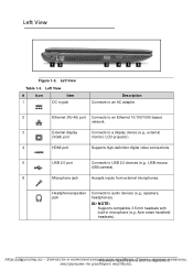
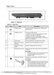
... lock cable around an immovable object such as a table or handle of a locked drawer. 9 Right view English 12 3 456 7 # Icon 1 2 3 4 5 6 7 Item USB 2.0 port Description Connects to a Kensington-compatible computer security lock. Optical drive Internal optical drive; Kensington lock slot Connects to USB 2.0 devices (e.g., USB mouse, USB camera). Optical drive eject button Ejects the optical disk from the drive. USB 2.0 / 3.0* port Connects to USB devices. * A USB 3.0 port can be compatible. Optical disk access indicator Lights up when the optical drive is turned...
... lock cable around an immovable object such as a table or handle of a locked drawer. 9 Right view English 12 3 456 7 # Icon 1 2 3 4 5 6 7 Item USB 2.0 port Description Connects to a Kensington-compatible computer security lock. Optical drive Internal optical drive; Kensington lock slot Connects to USB 2.0 devices (e.g., USB mouse, USB camera). Optical drive eject button Ejects the optical disk from the drive. USB 2.0 / 3.0* port Connects to USB devices. * A USB 3.0 port can be compatible. Optical disk access indicator Lights up when the optical drive is turned...
Service Guide
Page 7
... Disk Drive) Module Removal 3-16 HDD Module Installation 3-17 HDD Carrier Removal 3-18 HDD Carrier Installation 3-18 ODD Module Removal 3-19 ODD Module Installation 3-20 WLAN (Wireless Local Area Network) Module Removal . . . .3-21 WLAN Module Installation 3-21 DIMM (Dual In-line Memory Module) Module Removal . . . .3-22 DIMM Module Installation 3-22 Keyboard Removal 3-23 Keyboard Installation 3-24 Upper Cover Removal 3-25 Upper Cover Installation 3-27 Touchpad Board FFC Removal 3-28 Touchpad Board FFC Installation 3-29 Power Board Removal 3-30 Power Board Installation 3-30 USB...
... Disk Drive) Module Removal 3-16 HDD Module Installation 3-17 HDD Carrier Removal 3-18 HDD Carrier Installation 3-18 ODD Module Removal 3-19 ODD Module Installation 3-20 WLAN (Wireless Local Area Network) Module Removal . . . .3-21 WLAN Module Installation 3-21 DIMM (Dual In-line Memory Module) Module Removal . . . .3-22 DIMM Module Installation 3-22 Keyboard Removal 3-23 Keyboard Installation 3-24 Upper Cover Removal 3-25 Upper Cover Installation 3-27 Touchpad Board FFC Removal 3-28 Touchpad Board FFC Installation 3-29 Power Board Removal 3-30 Power Board Installation 3-30 USB...
Service Guide
Page 22
Communication indicator Power indicator Indicates the computer's wireless connectivity device status. Indicates the computer's power status. Charging: The light shows amber when the battery is active. Indicates when the hard disk drive is charging. Battery indicator Indicates the computer's battery status. Fully charged: The light shows blue when in AC mode. 7 Click buttons (left and The left and right) right mouse buttons. 8 Microphone Internal microphone for sound recording. http:/1/-1m2 ycomp.su HиaеrdдwлaяreнSоpуeт...
Communication indicator Power indicator Indicates the computer's wireless connectivity device status. Indicates the computer's power status. Charging: The light shows amber when the battery is active. Indicates when the hard disk drive is charging. Battery indicator Indicates the computer's battery status. Fully charged: The light shows blue when in AC mode. 7 Click buttons (left and The left and right) right mouse buttons. 8 Microphone Internal microphone for sound recording. http:/1/-1m2 ycomp.su HиaеrdдwлaяreнSоpуeт...
Service Guide
Page 24
...jack Description Connects to an AC adapter. 2 Ethernet (RJ-45) port Connects to an Ethernet 10/100/1000-based network. 3 External display Connects to a display device (e.g., external (VGA) port monitor, LCD projector). 4 HDMI port Supports high-definition digital video connections. 5 USB 2.0 port Connects to audio devices...;s Acer smart handheld headsets). Left View # Icon Item 1 DC-in microphone (e.g. Headphones/speaker jack Connects to USB 2.0 devices (e.g., USB mouse, USB camera). 6 Microphone jack Accepts inputs from external microphones. Left View ...
...jack Description Connects to an AC adapter. 2 Ethernet (RJ-45) port Connects to an Ethernet 10/100/1000-based network. 3 External display Connects to a display device (e.g., external (VGA) port monitor, LCD projector). 4 HDMI port Supports high-definition digital video connections. 5 USB 2.0 port Connects to audio devices...;s Acer smart handheld headsets). Left View # Icon Item 1 DC-in microphone (e.g. Headphones/speaker jack Connects to USB 2.0 devices (e.g., USB mouse, USB camera). 6 Microphone jack Accepts inputs from external microphones. Left View ...
Service Guide
Page 25
... computer security lock cable around an immovable object such as a table or handle of a locked drawer. Insert the lock into the notch and turn the key to USB devices. * A USB 3.0 port can be compatible. 3 Optical drive Internal optical drive; indicator 5 Optical drive eject Ejects the optical disc from the drive. Right View 0 12 3 456 7 Figure 1-4. accepts CDs or DVDs. 4 Optical drive access Lights up when the optical drive is active. Some keyless models are...
... computer security lock cable around an immovable object such as a table or handle of a locked drawer. Insert the lock into the notch and turn the key to USB devices. * A USB 3.0 port can be compatible. 3 Optical drive Internal optical drive; indicator 5 Optical drive eject Ejects the optical disc from the drive. Right View 0 12 3 456 7 Figure 1-4. accepts CDs or DVDs. 4 Optical drive access Lights up when the optical drive is active. Some keyless models are...
Service Guide
Page 28
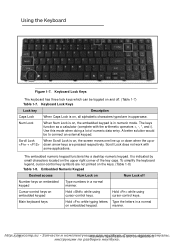
... the key caps. Scroll Lock When Scroll Lock is on embedded keypad Type numbers in numeric mode. To simplify the keyboard legend, cursor-control key symbols are not printed on , the screen moves one line up or down when the up or + down arrow keys are in a normal on embedded keypad Hold while using cursor-control keys. Scroll Lock does not work with the arithmetic operators +, -, *, and /). Num Lock When Num Lock...
... the key caps. Scroll Lock When Scroll Lock is on embedded keypad Type numbers in numeric mode. To simplify the keyboard legend, cursor-control key symbols are not printed on , the screen moves one line up or down when the up or + down arrow keys are in a normal on embedded keypad Hold while using cursor-control keys. Scroll Lock does not work with the arithmetic operators +, -, *, and /). Num Lock When Num Lock...
Service Guide
Page 30
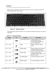
...1084;s Keyboard Hotkeys To activate hotkeys, press and hold the key before pressing the other key in Sleep mode. + + + Display toggle Screen blank Touchpad toggle Switches display output between the display screen, external monitor (if connected) and both. Press any key to access most of the computer's controls like screen brightness and volume output. Table 1-10. Turns the display screen backlight off . Keyboard Hotkeys Hotkey Icon Function + Communication switch + Sleep Description Enables/disables the computer's communication devices. (Communication devices may...
...1084;s Keyboard Hotkeys To activate hotkeys, press and hold the key before pressing the other key in Sleep mode. + + + Display toggle Screen blank Touchpad toggle Switches display output between the display screen, external monitor (if connected) and both. Press any key to access most of the computer's controls like screen brightness and volume output. Table 1-10. Turns the display screen backlight off . Keyboard Hotkeys Hotkey Icon Function + Communication switch + Sleep Description Enables/disables the computer's communication devices. (Communication devices may...
Service Guide
Page 63
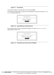
Setup Warning: Passwords Do Not Match http:/S/ysmteymcUotmilitpie.ssu 2с-1м1 If the password entered does not match the current password, the screen shows the Setup Warning dialog. (Figure 2-8) Figure 2-8. Setup Warning: Invalid Password If new password and confirm new password strings do not match, the Setup Warning dialog appears. (Figure 2-9) Figure 2-9. Setup Notice The password setting is complete after the user presses Enter. Figure 2-7.
Setup Warning: Passwords Do Not Match http:/S/ysmteymcUotmilitpie.ssu 2с-1м1 If the password entered does not match the current password, the screen shows the Setup Warning dialog. (Figure 2-8) Figure 2-8. Setup Warning: Invalid Password If new password and confirm new password strings do not match, the Setup Warning dialog appears. (Figure 2-9) Figure 2-9. Setup Notice The password setting is complete after the user presses Enter. Figure 2-7.
Service Guide
Page 114
...;s Install speaker modules. 8. Install WLAN module. 9. Install mainboard by sliding left side (A) at a slight angle into slots on left side of mainboard until edge is flush with adhesive tape. Lower right side (B) of mainboard (i.e. Mainboard Installation 0 1. Connect DC-IN (B) cable to Figure 3-36. 3. Install and secure WLAN cables (B) to left side of lower cover. Install and secure two (2) screws (A) to Figure 3-35. 6. Install HDD module. Flip...
...;s Install speaker modules. 8. Install WLAN module. 9. Install mainboard by sliding left side (A) at a slight angle into slots on left side of mainboard until edge is flush with adhesive tape. Lower right side (B) of mainboard (i.e. Mainboard Installation 0 1. Connect DC-IN (B) cable to Figure 3-36. 3. Install and secure WLAN cables (B) to left side of lower cover. Install and secure two (2) screws (A) to Figure 3-35. 6. Install HDD module. Flip...
Service Guide
Page 118
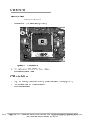
...;cиeсduмreаs http://3m-4y2comp.su Mуaтcбhуin Socket 2. Locate module (A) on mainboard (Figure 3-41). Turn captive screw (B) left 180º to secure module. 3. Turn screw (B) right 180º to release module. 3. Install thermal module. CPU Removal 0 Prerequisite: Thermal Module Removal 1. CPU Installation 0 1. A C B D Figure 3-41. Align CPU marker (C) with socket marker (D) and install CPU in socket (Figure 3-41). 2. Remove module from socket.
...;cиeсduмreаs http://3m-4y2comp.su Mуaтcбhуin Socket 2. Locate module (A) on mainboard (Figure 3-41). Turn captive screw (B) left 180º to secure module. 3. Turn screw (B) right 180º to release module. 3. Install thermal module. CPU Removal 0 Prerequisite: Thermal Module Removal 1. CPU Installation 0 1. A C B D Figure 3-41. Align CPU marker (C) with socket marker (D) and install CPU in socket (Figure 3-41). 2. Remove module from socket.
Service Guide
Page 139
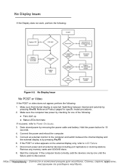
... or video appears on the external display only, refer to Power On Issues. 3. Make sure that internal display is by pressing Fn+F5. 6. Connect an external monitor to the computer and switch between internal and external by checking for one by removing the power cable and battery. Start the computer. No Display Issues 0 If the Display does not work, perform the following : 1. Remove any memory cards and CD/DVD discs. 8. If the computer boots correctly, add the devices...
... or video appears on the external display only, refer to Power On Issues. 3. Make sure that internal display is by pressing Fn+F5. 6. Connect an external monitor to the computer and switch between internal and external by checking for one by removing the power cable and battery. Start the computer. No Display Issues 0 If the Display does not work, perform the following : 1. Remove any memory cards and CD/DVD discs. 8. If the computer boots correctly, add the devices...
Service Guide
Page 140
... Online Support Information. Remove the drives. (refer to the User Manual for instructions on adjusting the settings. Refer to Maintenance Flowchart) 11. If the display is too dim at the highest brightness setting, the LCD is not normal, right-click on battery alone as this may reduce display brightness. 2. Remove and reinstall the video driver. 6. There are no red Xs or yellow exclamation marks There are no device...
... Online Support Information. Remove the drives. (refer to the User Manual for instructions on adjusting the settings. Refer to Maintenance Flowchart) 11. If the display is too dim at the highest brightness setting, the LCD is not normal, right-click on battery alone as this may reduce display brightness. 2. Remove and reinstall the video driver. 6. There are no red Xs or yellow exclamation marks There are no device...
Service Guide
Page 152
... Windows Vista Startup Repair Utility: a. NOTE: NOTE: Startup Repair attempts to resolve the problem. 1. Confirm all external devices. 2. Run Windows Check Disk by entering chkdsk /r from a known good date using up-to-date software to confirm the computer is not fixed, repeat the preceding steps and select an earlier time and date. 9. Replace the HDD. (refer to the operating system DVD. Check the BIOS settings are set as the first boot device on -screen information to locate...
... Windows Vista Startup Repair Utility: a. NOTE: NOTE: Startup Repair attempts to resolve the problem. 1. Confirm all external devices. 2. Run Windows Check Disk by entering chkdsk /r from a known good date using up-to-date software to confirm the computer is not fixed, repeat the preceding steps and select an earlier time and date. 9. Replace the HDD. (refer to the operating system DVD. Check the BIOS settings are set as the first boot device on -screen information to locate...
Service Guide
Page 155
... and click OK. 6. Click Properties. Select the Recording tab. Replace the ODD. (refer to enter the BIOS Utility. 2. If using different software, refer to Start Control Panel System and Maintenance System Device Manager. 4. Reseat the drive, making sure and all cables are not running low: Close some applications. Reboot and try the operation again. 2. Navigate to the software's user manual.
... and click OK. 6. Click Properties. Select the Recording tab. Replace the ODD. (refer to enter the BIOS Utility. 2. If using different software, refer to Start Control Panel System and Maintenance System Device Manager. 4. Reseat the drive, making sure and all cables are not running low: Close some applications. Reboot and try the operation again. 2. Navigate to the software's user manual.
Service Guide
Page 156
... experiencing HDD or ODD BIOS information loss, disconnect and reconnect the power and data cables between devices. 4. http://4m-2y2comp.su T,roсuеbрleвsиhoсoмtinаg Remove the power and remove the cover to inspect the connections to verify mouse operation. If the computer is more than one year old, replace the CMOS battery. 2. If the mouse uses a USB connection, use a different USB port. 4. Drive Read...
... experiencing HDD or ODD BIOS information loss, disconnect and reconnect the power and data cables between devices. 4. http://4m-2y2comp.su T,roсuеbрleвsиhoсoмtinаg Remove the power and remove the cover to inspect the connections to verify mouse operation. If the computer is more than one year old, replace the CMOS battery. 2. If the mouse uses a USB connection, use a different USB port. 4. Drive Read...
Service Guide
Page 157
... detected, do with a hardware defect, such as: cosmic radiation, electrostatic discharge, or software errors. Run the advanced diagnostic test for the system board in loop mode at the time of the following devices: Non-Acer devices Printer, mouse, and other external devices Battery pack Hard disk drive DIMM CD-ROM/Diskette drive Module PC Cards 4.
... detected, do with a hardware defect, such as: cosmic radiation, electrostatic discharge, or software errors. Run the advanced diagnostic test for the system board in loop mode at the time of the following devices: Non-Acer devices Printer, mouse, and other external devices Battery pack Hard disk drive DIMM CD-ROM/Diskette drive Module PC Cards 4.


