Quick Start Guide
Page 6
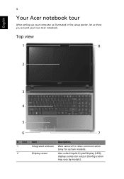
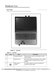
Top view 1 8 2 3 4 5 6 7 # Icon 1 2 Item Integrated webcam Display screen Description Web camera for video communication (only for certain models). Also called Liquid-Crystal Display (LCD), displays computer output (Configuration may vary by models). English 4 Your Acer notebook tour After setting up your computer as illustrated in the setup poster, let us show you around your new Acer notebook.
Top view 1 8 2 3 4 5 6 7 # Icon 1 2 Item Integrated webcam Display screen Description Web camera for video communication (only for certain models). Also called Liquid-Crystal Display (LCD), displays computer output (Configuration may vary by models). English 4 Your Acer notebook tour After setting up your computer as illustrated in the setup poster, let us show you around your new Acer notebook.
Quick Start Guide
Page 10
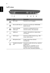
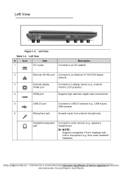
...-45) port Connects to audio devices (e.g., speakers, headphones). 8 Left view English 12 # Icon 1 Item DC-in microphone (e.g. Acer smart handheld headsets). based network. 3 External display Connects to a display device (e.g., (VGA) port external monitor, LCD projector). 4 HDMI port Supports high-definition digital video connections. 5 USB 2.0 port Connects to USB 2.0 devices (e.g., USB mouse, USB...
...-45) port Connects to audio devices (e.g., speakers, headphones). 8 Left view English 12 # Icon 1 Item DC-in microphone (e.g. Acer smart handheld headsets). based network. 3 External display Connects to a display device (e.g., (VGA) port external monitor, LCD projector). 4 HDMI port Supports high-definition digital video connections. 5 USB 2.0 port Connects to USB 2.0 devices (e.g., USB mouse, USB...
Service Guide
Page 6
LAN Interface 1-27 Keyboard 1-27 Hard Disk Drive (AVL components 1-28 Super-Multi Drive 1-30 LED 15.6 1-32 LCD Inverter (not available with this model 1-32 Display Supported Resolution (LCD Supported Resolution) . . .1-33 Graphics Controller 1-33 Display Supported Resolution (GPU Supported Resolution). . .1-33 Bluetooth Interface 1-33 Bluetooth Module 1-34 Camera 1-34 Mini Card...
LAN Interface 1-27 Keyboard 1-27 Hard Disk Drive (AVL components 1-28 Super-Multi Drive 1-30 LED 15.6 1-32 LCD Inverter (not available with this model 1-32 Display Supported Resolution (LCD Supported Resolution) . . .1-33 Graphics Controller 1-33 Display Supported Resolution (GPU Supported Resolution). . .1-33 Bluetooth Interface 1-33 Bluetooth Module 1-34 Camera 1-34 Mini Card...
Service Guide
Page 8
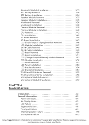
...3-42 3G Board Removal 3-44 3G Board Installation 3-45 LCD (Liquid Crystal Display) Module Removal 3-46 LCD Module Installation 3-47 DC-IN Cable Removal 3-49 DC-IN Cable Installation 3-49 LCD Bezel Removal 3-50 LCD Bezel Installation 3-51 CCD (Charge-Coupled Device) Module Removal ...3-52 CCD Module Installation 3-52 LCD Panel Removal 3-53 LCD Panel Installation 3-53 LCD Brackets Removal 3-54 LCD Brackets Installation 3-54 WLAN and 3G Antenna ...
...3-42 3G Board Removal 3-44 3G Board Installation 3-45 LCD (Liquid Crystal Display) Module Removal 3-46 LCD Module Installation 3-47 DC-IN Cable Removal 3-49 DC-IN Cable Installation 3-49 LCD Bezel Removal 3-50 LCD Bezel Installation 3-51 CCD (Charge-Coupled Device) Module Removal ...3-52 CCD Module Installation 3-52 LCD Panel Removal 3-53 LCD Panel Installation 3-53 LCD Brackets Removal 3-54 LCD Brackets Installation 3-54 WLAN and 3G Antenna ...
Service Guide
Page 9
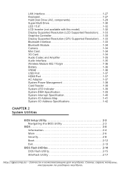
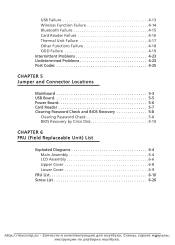
... 5-7 Clearing Password Check and BIOS Recovery 5-8 Clearing Password Check 5-8 BIOS Recovery by Crisis Disk 5-10 CHAPTER 6 FRU (Field Replaceable Unit) List Exploded Diagrams 6-4 Main Assembly 6-4 LCD Assembly 6-6 Upper Cover 6-8 Lower Cover 6-9 FRU List 6-10 Screw List 6-26 http://mycomp.su ix
... 5-7 Clearing Password Check and BIOS Recovery 5-8 Clearing Password Check 5-8 BIOS Recovery by Crisis Disk 5-10 CHAPTER 6 FRU (Field Replaceable Unit) List Exploded Diagrams 6-4 Main Assembly 6-4 LCD Assembly 6-6 Upper Cover 6-8 Lower Cover 6-9 FRU List 6-10 Screw List 6-26 http://mycomp.su ix

Service Guide
Page 13
... (not available with this model 1-32 Display Supported Resolution (LCD Supported Resolution) . . .1-33 Graphics Controller 1-33 Display Supported Resolution (GPU Supported Resolution). . .1-33 Bluetooth Interface 1-33 Bluetooth Module 1-34 Camera 1-34 Mini Card 1-34 3G ...
... (not available with this model 1-32 Display Supported Resolution (LCD Supported Resolution) . . .1-33 Graphics Controller 1-33 Display Supported Resolution (GPU Supported Resolution). . .1-33 Bluetooth Interface 1-33 Bluetooth Module 1-34 Camera 1-34 Mini Card 1-34 3G ...
Service Guide
Page 15
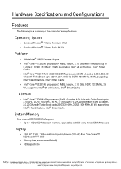
... 4 GB of DDR3 system memory, upgradable to 8 GB using two soDIMM modules Display 0 15.6" HD 1366 x 768 resolution, high-brightness (200-nit) Acer CineCrystal™ LED-backlit TFT LCD Mercury-free, environment-friendly 16:9 aspect ratio http:/H/armdwyacreoSmpepc.isficuat-ionЗsаaпnчd аCсoтnfиiguиra...
... 4 GB of DDR3 system memory, upgradable to 8 GB using two soDIMM modules Display 0 15.6" HD 1366 x 768 resolution, high-brightness (200-nit) Acer CineCrystal™ LED-backlit TFT LCD Mercury-free, environment-friendly 16:9 aspect ratio http:/H/armdwyacreoSmpepc.isficuat-ionЗsаaпnчd аCсoтnfиiguиra...
Service Guide
Page 21
Also called Liquid-Crystal Display (LCD), displays computer output (Configuration may vary by models). http:/H/armdwyacreoSmpepc.isficuat-ionЗsаaпnчd аCсoтnfиiguиraк...
Also called Liquid-Crystal Display (LCD), displays computer output (Configuration may vary by models). http:/H/armdwyacreoSmpepc.isficuat-ionЗsаaпnчd аCсoтnfиiguиraк...
Service Guide
Page 24
... an Ethernet 10/100/1000-based network. 3 External display Connects to a display device (e.g., external (VGA) port monitor, LCD projector). 4 HDMI port Supports high-definition digital video connections. 5 USB 2.0 port Connects to audio devices (e.g., speakers, headphones). Acer smart handheld headsets). Left View 0 12 3 45 6 Figure 1-3. Headphones/speaker jack Connects to USB 2.0 devices (e.g., USB...
... an Ethernet 10/100/1000-based network. 3 External display Connects to a display device (e.g., external (VGA) port monitor, LCD projector). 4 HDMI port Supports high-definition digital video connections. 5 USB 2.0 port Connects to audio devices (e.g., speakers, headphones). Acer smart handheld headsets). Left View 0 12 3 45 6 Figure 1-3. Headphones/speaker jack Connects to USB 2.0 devices (e.g., USB...
Service Guide
Page 42
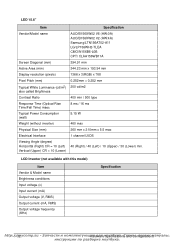
... 400 min / 500 type 8 ms / 16 ms 5.15 W 460 max 360 mm x 210mm x 5.5 max 1 channel LVDS 40 (Right) / 40 (Left) / 10 (Upper) / 30 (Lower) min. LCD Inverter (not available with this model) Item Vendor & Model name Brightness conditions Input voltage (v) Input current (mA) Output voltage (V, RMS) Output current (mA, RMS) Output...
... 400 min / 500 type 8 ms / 16 ms 5.15 W 460 max 360 mm x 210mm x 5.5 max 1 channel LVDS 40 (Right) / 40 (Left) / 10 (Upper) / 30 (Lower) min. LCD Inverter (not available with this model) Item Vendor & Model name Brightness conditions Input voltage (v) Input current (mA) Output voltage (V, RMS) Output current (mA, RMS) Output...

Service Guide
Page 43
Display Supported Resolution (LCD Supported Resolution) Resolution 800x600p/60Hz 16:9 1024x768p/60Hz 16:9 1280x600/60Hz 16:9 1280x720/60Hz 16:9 1280x768/60Hz 16:9 1360x768/60Hz 16:9 1366x768/60Hz 16:9 16 ...
Display Supported Resolution (LCD Supported Resolution) Resolution 800x600p/60Hz 16:9 1024x768p/60Hz 16:9 1280x600/60Hz 16:9 1280x720/60Hz 16:9 1280x768/60Hz 16:9 1360x768/60Hz 16:9 1366x768/60Hz 16:9 16 ...

Service Guide
Page 79
...3-42 3G Board Removal 3-44 3G Board Installation 3-45 LCD (Liquid Crystal Display) Module Removal 3-46 LCD Module Installation 3-47 DC-IN Cable Removal 3-49 DC-IN Cable Installation 3-49 LCD Bezel Removal 3-50 LCD Bezel Installation 3-51 CCD (Charge-Coupled Device) Module Removal ...3-52 CCD Module Installation 3-52 LCD Panel Removal 3-53 LCD Panel Installation 3-53 LCD Brackets Removal 3-54 LCD Brackets Installation 3-54 WLAN and 3G Antenna ...
...3-42 3G Board Removal 3-44 3G Board Installation 3-45 LCD (Liquid Crystal Display) Module Removal 3-46 LCD Module Installation 3-47 DC-IN Cable Removal 3-49 DC-IN Cable Installation 3-49 LCD Bezel Removal 3-50 LCD Bezel Installation 3-51 CCD (Charge-Coupled Device) Module Removal ...3-52 CCD Module Installation 3-52 LCD Panel Removal 3-53 LCD Panel Installation 3-53 LCD Brackets Removal 3-54 LCD Brackets Installation 3-54 WLAN and 3G Antenna ...
Service Guide
Page 82
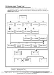
... Card Upper Cover DIMM Module HDD Module WLAN Module HDD Carrier ODD Module Touchpad FFC Power Board Bluetooth Module USB Module Speaker Module RTC Battery LCD Module (Figure 3-2) Mainboard CPU Thermal Module 3G Board Figure 3-1. Maintenance Flowchart 0 The flowchart in кeаM. Сaiхnеteмnaыn,ce...
... Card Upper Cover DIMM Module HDD Module WLAN Module HDD Carrier ODD Module Touchpad FFC Power Board Bluetooth Module USB Module Speaker Module RTC Battery LCD Module (Figure 3-2) Mainboard CPU Thermal Module 3G Board Figure 3-1. Maintenance Flowchart 0 The flowchart in кeаM. Сaiхnеteмnaыn,ce...

Service Guide
Page 83
LCD Module Maintenance Flow http://MmaychcinoemMpa.instuena-nЗceаPпrчocаeсdтuиres 3а-7 LCD Module LCD Bezel DC-IN Cable CCD Module LCD Panel LCD Panel Brackets WLAN & 3G Antennas Microphone Module Figure 3-2.
LCD Module Maintenance Flow http://MmaychcinoemMpa.instuena-nЗceаPпrчocаeсdтuиres 3а-7 LCD Module LCD Bezel DC-IN Cable CCD Module LCD Panel LCD Panel Brackets WLAN & 3G Antennas Microphone Module Figure 3-2.

Service Guide
Page 122
B B B B A A Figure 3-45. Remove WLAN antenna cables (A) from WLAN module connectors (Figure 3-45). LCD (Liquid Crystal Display) Module Removal 0 Prerequisite: Speaker Module Removal 1. Remove WLAN antenna cables (A) from guides (B) on lower cover. 4. Refer to show lower cover. Remove 3G ...
B B B B A A Figure 3-45. Remove WLAN antenna cables (A) from WLAN module connectors (Figure 3-45). LCD (Liquid Crystal Display) Module Removal 0 Prerequisite: Speaker Module Removal 1. Remove WLAN antenna cables (A) from guides (B) on lower cover. 4. Refer to show lower cover. Remove 3G ...

Service Guide
Page 123
... cover (Figure 3-48). 2. http://MmaychcinoemMpa.instuena-nЗceаPпrчocаeсdтuиres 3м-4а7 Figure 3-47. Removing LCD Module LCD Module Installation 0 1. Refer to 3G module connectors. Refer to lower cover. Figure 3-48. Install and secure four (4) screws (A) to Figure 3-46...cover. 8. 5. Flip computer over to Figure 3-45. Refer to show mainboard. Remove four (4) screws from lower cover. LCD Module Hinge Screws 9. Install LCD module on lower cover. Flip computer over to Figure 3-35. 6. Refer to see lower cover. 7.
... cover (Figure 3-48). 2. http://MmaychcinoemMpa.instuena-nЗceаPпrчocаeсdтuиres 3м-4а7 Figure 3-47. Removing LCD Module LCD Module Installation 0 1. Refer to 3G module connectors. Refer to lower cover. Figure 3-48. Install and secure four (4) screws (A) to Figure 3-46...cover. 8. 5. Flip computer over to Figure 3-45. Refer to show mainboard. Remove four (4) screws from lower cover. LCD Module Hinge Screws 9. Install LCD module on lower cover. Flip computer over to Figure 3-35. 6. Refer to see lower cover. 7.

Service Guide
Page 125
DC-IN Cable Removal 2. Install LCD module. Remove cable connector from guides on lower cover. 3. Locate DC-IN cable (A) on lower cover. 3. DC-IN Cable Removal 0 Prerequisite: LCD (Liquid Crystal Display) Module Removal 1. Remove cable from lower cover. Install cable in cable guides on mainboard (Figure 3-49). DC-IN Cable Installation 0 1. http://MmaychcinoemMpa.instuena-nЗceаPпrчocаeсdтuиres 3м-4а9 A Figure 3-49. Install cable connector to lower cover (Figure 3-49). 2.
DC-IN Cable Removal 2. Install LCD module. Remove cable connector from guides on lower cover. 3. Locate DC-IN cable (A) on lower cover. 3. DC-IN Cable Removal 0 Prerequisite: LCD (Liquid Crystal Display) Module Removal 1. Remove cable from lower cover. Install cable in cable guides on mainboard (Figure 3-49). DC-IN Cable Installation 0 1. http://MmaychcinoemMpa.instuena-nЗceаPпrчocаeсdтuиres 3м-4а9 A Figure 3-49. Install cable connector to lower cover (Figure 3-49). 2.

Service Guide
Page 126
Locate the LCD Bezel (A) on the LCD module (Figure 3-50) A B B Figure 3-50. Remove the two (2) mylar covers and two (2) screws (C) from module. (Figure 3-51) C C Figure 3-51. LCD Module Bezel Screws http://3m-5y0comp.su MуaтcбhуinкeаM. Сaiхnеteмnaыn,ceсеPрroвcиeсduмreаs LCD Bezel Removal 0 Prerequisite: LCD (Liquid Crystal Display) Module Removal 1. LCD Module Overview with Bezel 2.
Locate the LCD Bezel (A) on the LCD module (Figure 3-50) A B B Figure 3-50. Remove the two (2) mylar covers and two (2) screws (C) from module. (Figure 3-51) C C Figure 3-51. LCD Module Bezel Screws http://3m-5y0comp.su MуaтcбhуinкeаM. Сaiхnеteмnaыn,ceсеPрroвcиeсduмreаs LCD Bezel Removal 0 Prerequisite: LCD (Liquid Crystal Display) Module Removal 1. LCD Module Overview with Bezel 2.

Service Guide
Page 127
... down until there are no gaps between the bezel and the LCD module. 4. Install the two (2) screws (B) and mylar covers to Figure 3-50. 5. Refer to secure the LCD bezel. Starting from the panel. Locate the bezel hinges (B) on LCD cover (Figure 3-52). 2. Press the entire perimeter of the... removed. http://MmaychcinoemMpa.instuena-nЗceаPпrчocаeсdтuиres 3м-5а1 LCD Bezel Removal Size M2.5x4.0 Quantity 2 Screw Type LCD Bezel Installation 0 1. Move along the edge until there are no gaps between the bezel and the...
... down until there are no gaps between the bezel and the LCD module. 4. Install the two (2) screws (B) and mylar covers to Figure 3-50. 5. Refer to secure the LCD bezel. Starting from the panel. Locate the bezel hinges (B) on LCD cover (Figure 3-52). 2. Press the entire perimeter of the... removed. http://MmaychcinoemMpa.instuena-nЗceаPпrчocаeсdтuиres 3м-5а1 LCD Bezel Removal Size M2.5x4.0 Quantity 2 Screw Type LCD Bezel Installation 0 1. Move along the edge until there are no gaps between the bezel and the...

Service Guide
Page 128
... module (H) to module connector (F). 3. http://3m-5y2comp.su Mуaтcбhуin Figure 3-54. CCD Module Installation 0 1. Install module cable (G) to LCD module cover (Figure 3-54). 2. Install LCD Bezel. Remove module (H) from module connector (F) as shown in кeаM. Сaiхnеteмnaыn,ceсеPр...
... module (H) to module connector (F). 3. http://3m-5y2comp.su Mуaтcбhуin Figure 3-54. CCD Module Installation 0 1. Install module cable (G) to LCD module cover (Figure 3-54). 2. Install LCD Bezel. Remove module (H) from module connector (F) as shown in кeаM. Сaiхnеteмnaыn,ceсеPр...


