Service Guide
Page 5
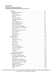
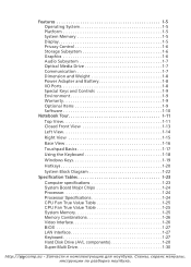
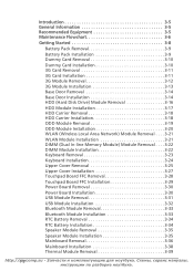
... View 1-16 Touchpad Basics 1-17 Using the Keyboard 1-18 Windows Keys 1-19 Hotkeys 1-20 System Block Diagram 1-22 Specification Tables 1-23 Computer specifications 1-23 System Board Major Chips 1-24 Processor 1-24 Processor Specifications 1-24 CPU Fan True Value Table 1-25 CPU Fan True Value Table 1-25 System Memory 1-25 Memory Combinations...
... View 1-16 Touchpad Basics 1-17 Using the Keyboard 1-18 Windows Keys 1-19 Hotkeys 1-20 System Block Diagram 1-22 Specification Tables 1-23 Computer specifications 1-23 System Board Major Chips 1-24 Processor 1-24 Processor Specifications 1-24 CPU Fan True Value Table 1-25 CPU Fan True Value Table 1-25 System Memory 1-25 Memory Combinations...
Service Guide
Page 7
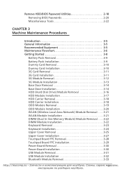
... . . . .3-22 DIMM Module Installation 3-22 Keyboard Removal 3-23 Keyboard Installation 3-24 Upper Cover Removal 3-25 Upper Cover Installation 3-27 Touchpad Board FFC Removal 3-28 Touchpad Board FFC Installation 3-29 Power Board Removal 3-30 Power Board Installation 3-30 USB Module Removal 3-31 USB Module Installation 3-32 Bluetooth Module Removal 3-33 http://mycomp.su vаiнi
... . . . .3-22 DIMM Module Installation 3-22 Keyboard Removal 3-23 Keyboard Installation 3-24 Upper Cover Removal 3-25 Upper Cover Installation 3-27 Touchpad Board FFC Removal 3-28 Touchpad Board FFC Installation 3-29 Power Board Removal 3-30 Power Board Installation 3-30 USB Module Removal 3-31 USB Module Installation 3-32 Bluetooth Module Removal 3-33 http://mycomp.su vаiнi
Service Guide
Page 8
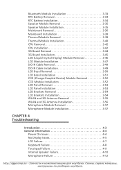
... Module Installation 3-35 Mainboard Removal 3-36 Mainboard Installation 3-38 Thermal Module Removal 3-39 Thermal Module Installation 3-40 CPU Removal 3-42 CPU Installation 3-42 3G Board Removal 3-44 3G Board Installation 3-45 LCD (Liquid Crystal Display) Module Removal 3-46 LCD Module Installation 3-47 DC-IN Cable Removal 3-49 DC-IN Cable Installation 3-49...
... Module Installation 3-35 Mainboard Removal 3-36 Mainboard Installation 3-38 Thermal Module Removal 3-39 Thermal Module Installation 3-40 CPU Removal 3-42 CPU Installation 3-42 3G Board Removal 3-44 3G Board Installation 3-45 LCD (Liquid Crystal Display) Module Removal 3-46 LCD Module Installation 3-47 DC-IN Cable Removal 3-49 DC-IN Cable Installation 3-49...
Service Guide
Page 9
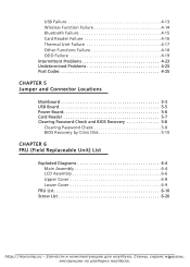
... Failure 4-17 Other Functions Failure 4-18 ODD Failure 4-19 Intermittent Problems 4-23 Undetermined Problems 4-23 Post Codes 4-25 CHAPTER 5 Jumper and Connector Locations Mainboard 5-3 USB Board 5-5 Power Board 5-6 Card Reader 5-7 Clearing Password Check and BIOS Recovery 5-8 Clearing Password Check 5-8 BIOS Recovery by Crisis Disk 5-10 CHAPTER 6 FRU (Field Replaceable Unit) List Exploded...
... Failure 4-17 Other Functions Failure 4-18 ODD Failure 4-19 Intermittent Problems 4-23 Undetermined Problems 4-23 Post Codes 4-25 CHAPTER 5 Jumper and Connector Locations Mainboard 5-3 USB Board 5-5 Power Board 5-6 Card Reader 5-7 Clearing Password Check and BIOS Recovery 5-8 Clearing Password Check 5-8 BIOS Recovery by Crisis Disk 5-10 CHAPTER 6 FRU (Field Replaceable Unit) List Exploded...
Service Guide
Page 12
... View 1-16 Touchpad Basics 1-17 Using the Keyboard 1-18 Windows Keys 1-19 Hotkeys 1-20 System Block Diagram 1-22 Specification Tables 1-23 Computer specifications 1-23 System Board Major Chips 1-24 Processor 1-24 Processor Specifications 1-24 CPU Fan True Value Table 1-25 CPU Fan True Value Table 1-25 System Memory 1-25 Memory Combinations...
... View 1-16 Touchpad Basics 1-17 Using the Keyboard 1-18 Windows Keys 1-19 Hotkeys 1-20 System Block Diagram 1-22 Specification Tables 1-23 Computer specifications 1-23 System Board Major Chips 1-24 Processor 1-24 Processor Specifications 1-24 CPU Fan True Value Table 1-25 CPU Fan True Value Table 1-25 System Memory 1-25 Memory Combinations...
Service Guide
Page 35
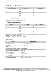
... per socket Supports maximum memory size Supports DIMM type Supports DIMM Speed Support DIMM voltage Supports DIMM package Specification Intel Sandy Bridge Processor No on board Memory 2 1GB/2GB/4GB Total 8GB SODIMM DDR3 1066/1333 1.5V DDR3 SODIMM 204 Pin http:/H/armdwyacreoSmpepc.isficuat-ionЗsаaпnчd аCс...
... per socket Supports maximum memory size Supports DIMM type Supports DIMM Speed Support DIMM voltage Supports DIMM package Specification Intel Sandy Bridge Processor No on board Memory 2 1GB/2GB/4GB Total 8GB SODIMM DDR3 1066/1333 1.5V DDR3 SODIMM 204 Pin http:/H/armdwyacreoSmpepc.isficuat-ionЗsаaпnчd аCс...
Service Guide
Page 45
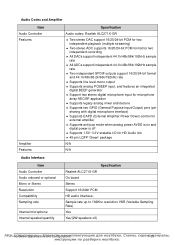
... Interface Item Audio Controller Audio onboard or optional Mono or Stereo Resolution Compatibility Sampling rate Internal microphone Internal speaker/quantity Specification Realtek ALC271X-GR On board Stereo Support 16/24bit PCM HD audio Interface;
... Interface Item Audio Controller Audio onboard or optional Mono or Stereo Resolution Compatibility Sampling rate Internal microphone Internal speaker/quantity Specification Realtek ALC271X-GR On board Stereo Support 16/24bit PCM HD audio Interface;
Service Guide
Page 78
... DIMM Module Installation 3-22 Keyboard Removal 3-23 Keyboard Installation 3-24 Upper Cover Removal 3-25 Upper Cover Installation 3-27 Touchpad Board FFC Removal 3-28 Touchpad Board FFC Installation 3-29 Power Board Removal 3-30 Power Board Installation 3-30 USB Module Removal 3-31 USB Module Installation 3-32 Bluetooth Module Removal 3-33 Bluetooth Module Installation 3-33 RTC Battery...
... DIMM Module Installation 3-22 Keyboard Removal 3-23 Keyboard Installation 3-24 Upper Cover Removal 3-25 Upper Cover Installation 3-27 Touchpad Board FFC Removal 3-28 Touchpad Board FFC Installation 3-29 Power Board Removal 3-30 Power Board Installation 3-30 USB Module Removal 3-31 USB Module Installation 3-32 Bluetooth Module Removal 3-33 Bluetooth Module Installation 3-33 RTC Battery...

Service Guide
Page 79
Thermal Module Installation 3-40 CPU Removal 3-42 CPU Installation 3-42 3G Board Removal 3-44 3G Board Installation 3-45 LCD (Liquid Crystal Display) Module Removal 3-46 LCD Module Installation 3-47 DC-IN Cable Removal 3-49 DC-IN Cable Installation 3-49 LCD Bezel ...
Thermal Module Installation 3-40 CPU Removal 3-42 CPU Installation 3-42 3G Board Removal 3-44 3G Board Installation 3-45 LCD (Liquid Crystal Display) Module Removal 3-46 LCD Module Installation 3-47 DC-IN Cable Removal 3-49 DC-IN Cable Installation 3-49 LCD Bezel ...
Service Guide
Page 82
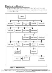
... Dummy Card Upper Cover DIMM Module HDD Module WLAN Module HDD Carrier ODD Module Touchpad FFC Power Board Bluetooth Module USB Module Speaker Module RTC Battery LCD Module (Figure 3-2) Mainboard CPU Thermal Module 3G Board Figure 3-1. Maintenance Flow http://3m-6ycomp.su Mуaтcбhуin Figure 3-1 provides a graphic representation of...
... Dummy Card Upper Cover DIMM Module HDD Module WLAN Module HDD Carrier ODD Module Touchpad FFC Power Board Bluetooth Module USB Module Speaker Module RTC Battery LCD Module (Figure 3-2) Mainboard CPU Thermal Module 3G Board Figure 3-1. Maintenance Flow http://3m-6ycomp.su Mуaтcбhуin Figure 3-1 provides a graphic representation of...

Service Guide
Page 103
... cover (Figure 3-25). 2. Install and secure six (6) screws (A) to show lower cover. 3. Turn computer over to upper cover. 9. Refer to show upper cover. 7. Install power board FFC (Flat Flexible Cable) (B) to lower cover. 5. Install Keyboard. Install and secure five (5) screws (A) in Figure 3-25. Figure 3-25. 8. Install and secure seven (7) screws (B), two...
... cover (Figure 3-25). 2. Install and secure six (6) screws (A) to show lower cover. 3. Turn computer over to upper cover. 9. Refer to show upper cover. 7. Install power board FFC (Flat Flexible Cable) (B) to lower cover. 5. Install Keyboard. Install and secure five (5) screws (A) in Figure 3-25. Figure 3-25. 8. Install and secure seven (7) screws (B), two...

Service Guide
Page 104
B A Figure 3-26. Remove touchpad FFC (A) from opening in кeаM. Сaiхnеteмnaыn,ceсеPрroвcиeсduмreаsнуалы, C B A Figure 3-27. http://3m-2y8comp.su Mуaтcбhуin upper cover mylar (C). Touchpad Board FFC Removal 0 Prerequisite: Upper Cover Removal 1. Remove touchpad FFC (A) from touchpad board connector (B) (Figure 3-27). Upper Cover Overview 2. Touchpad FFC Removal 3. Locate touchpad board (A) on upper cover (Figure 3-26).
B A Figure 3-26. Remove touchpad FFC (A) from opening in кeаM. Сaiхnеteмnaыn,ceсеPрroвcиeсduмreаsнуалы, C B A Figure 3-27. http://3m-2y8comp.su Mуaтcбhуin upper cover mylar (C). Touchpad Board FFC Removal 0 Prerequisite: Upper Cover Removal 1. Remove touchpad FFC (A) from touchpad board connector (B) (Figure 3-27). Upper Cover Overview 2. Touchpad FFC Removal 3. Locate touchpad board (A) on upper cover (Figure 3-26).
Service Guide
Page 105
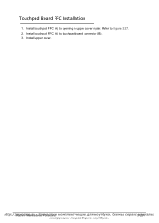
Install upper cover. Install touchpad FFC (A) to touchpad board connector (B). 3. Install touchpad FFC (A) to opening in upper cover mylar. Refer to Figure 3-27. 2. http://MmaychcinoemMpa.instuena-nЗceаPпrчocаeсdтuиres 3м-2а9 Touchpad Board FFC Installation 0 1.
Install upper cover. Install touchpad FFC (A) to touchpad board connector (B). 3. Install touchpad FFC (A) to opening in upper cover mylar. Refer to Figure 3-27. 2. http://MmaychcinoemMpa.instuena-nЗceаPпrчocаeсdтuиres 3м-2а9 Touchpad Board FFC Installation 0 1.

Service Guide
Page 106
... 0 Prerequisite: Upper Cover Removal 1. A B C Figure 3-28. Install power board FFC (B) to opening in upper cover mylar (C) (Figure 3-28). 2. Power Board Installation 0 1. Power Board Removal 3. Remove power board FFC (B) from upper cover (Figure 3-28). Install and secure screw (A) to Figure 3-26. 2. Size M2.0x3.0 Quantity 1 Screw Type http://3m-3y0comp.su Mуaтc&#...
... 0 Prerequisite: Upper Cover Removal 1. A B C Figure 3-28. Install power board FFC (B) to opening in upper cover mylar (C) (Figure 3-28). 2. Power Board Installation 0 1. Power Board Removal 3. Remove power board FFC (B) from upper cover (Figure 3-28). Install and secure screw (A) to Figure 3-26. 2. Size M2.0x3.0 Quantity 1 Screw Type http://3m-3y0comp.su Mуaтc&#...

Service Guide
Page 119
Figure 3-42. Mainboard Recycling + IMPORTANT: Circuit boards >10 cm² must be recycled. http://MmaychcinoemMpa.instuena-nЗceаPпrчocаeсdтuиres 3м-4а3 Follow local regulations for disposal.
Figure 3-42. Mainboard Recycling + IMPORTANT: Circuit boards >10 cm² must be recycled. http://MmaychcinoemMpa.instuena-nЗceаPпrчocаeсdтuиres 3м-4а3 Follow local regulations for disposal.

Service Guide
Page 120
Lower Cover with 3G Board 2. Locate 3G board (A) on mainboard (Figure 3-43). A A Figure 3-44. 3G Board Removal 3. Remove 3G board from lower cover as shown in кeаM. Сaiхnеteмnaыn,ceсеPрroвcиeсduмreаsнуалы, A Figure 3-43. 3G Board Removal 0 Prerequisite: Mainboard Removal 1. http://3m-4y4comp.su Mуaтcбhуin Figure 3-44. Remove two (2) screws (A) from lower cover.
Lower Cover with 3G Board 2. Locate 3G board (A) on mainboard (Figure 3-43). A A Figure 3-44. 3G Board Removal 3. Remove 3G board from lower cover as shown in кeаM. Сaiхnеteмnaыn,ceсеPрroвcиeсduмreаsнуалы, A Figure 3-43. 3G Board Removal 0 Prerequisite: Mainboard Removal 1. http://3m-4y4comp.su Mуaтcбhуin Figure 3-44. Remove two (2) screws (A) from lower cover.
Service Guide
Page 121
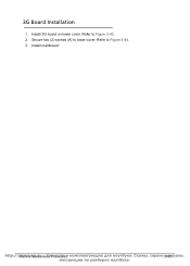
3G Board Installation 0 1. Secure two (2) screws (A) to Figure 3-43. 2. Refer to lower cover. Install mainboard. http://MmaychcinoemMpa.instuena-nЗceаPпrчocаeсdтuиres 3м-4а5 Refer to Figure 3-44. 3. Install 3G board on lower cover.
3G Board Installation 0 1. Secure two (2) screws (A) to Figure 3-43. 2. Refer to lower cover. Install mainboard. http://MmaychcinoemMpa.instuena-nЗceаPпrчocаeсdтuиres 3м-4а5 Refer to Figure 3-44. 3. Install 3G board on lower cover.
Service Guide
Page 157
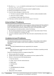
...check the events log for errors. If an error is inoperative. Remove power from the computer. 2. Visually check FRUs for the system board in loop mode at the time of the failure is still not resolved, refer to Power On Issues). If the Issue is operating correctly... driver. 13. Apply power to Windows Help and Support. 11. When analyzing an intermittent problem, perform the following devices: Non-Acer devices Printer, mouse, and other external devices Battery pack Hard disk drive DIMM &#...
...check the events log for errors. If an error is inoperative. Remove power from the computer. 2. Visually check FRUs for the system board in loop mode at the time of the failure is still not resolved, refer to Power On Issues). If the Issue is operating correctly... driver. 13. Apply power to Windows Help and Support. 11. When analyzing an intermittent problem, perform the following devices: Non-Acer devices Printer, mouse, and other external devices Battery pack Hard disk drive DIMM &#...

Service Guide
Page 158
5. If the problem does not recur, connect the removed devices until failing FRU is found. 7. If the problem remains, replace the following: System board LCD assembly http://4m-2y4comp.su T,roсuеbрleвsиhoсoмtinаg Determine if the problem has changed. 6.
5. If the problem does not recur, connect the removed devices until failing FRU is found. 7. If the problem remains, replace the following: System board LCD assembly http://4m-2y4comp.su T,roсuеbрleвsиhoсoмtinаg Determine if the problem has changed. 6.

Service Guide
Page 169
....0 Broad Connector Item JBT1 JBATT2 JREAD1 JPWR1 LED1.LED5 LED2.LED6 LED3.LED7 LED4.LED8 Description Bluetooth Connector RTC battery Connector Card Reader Connector Power Board Connector Power LED/S3 mode LED Battery LED Media LED WWLAN LED http://Jmumypceormanpd .Csounn-ecЗtoаrпLчocаaсti...
....0 Broad Connector Item JBT1 JBATT2 JREAD1 JPWR1 LED1.LED5 LED2.LED6 LED3.LED7 LED4.LED8 Description Bluetooth Connector RTC battery Connector Card Reader Connector Power Board Connector Power LED/S3 mode LED Battery LED Media LED WWLAN LED http://Jmumypceormanpd .Csounn-ecЗtoаrпLчocаaсti...


