
Acer Aspire 1640 Service Guide
Page 2
Date 200512/27 2006/02/15 Chapter Chapter 1 Chapter 3 Updates Revise memory specification to the table below for the updates made on page 20. Revise disassembling SOP. 2 Revision History Please refer to 533MHz on Aspire 1640 service guide.
Date 200512/27 2006/02/15 Chapter Chapter 1 Chapter 3 Updates Revise memory specification to the table below for the updates made on page 20. Revise disassembling SOP. 2 Revision History Please refer to 533MHz on Aspire 1640 service guide.

Acer Aspire 1640 Service Guide
Page 50
... driver T Hexed Screw Driver NOTE: The screws for maintenance and troubleshooting. During the disassembly process, group the screws with the corresponding components to disassemble the notebook computer for the different components vary in size. Chapter 3 46 Chapter 3 Machine Disassembly and Replacement This chapter contains step-by-step procedures on how to avoid mismatch...
... driver T Hexed Screw Driver NOTE: The screws for maintenance and troubleshooting. During the disassembly process, group the screws with the corresponding components to disassemble the notebook computer for the different components vary in size. Chapter 3 46 Chapter 3 Machine Disassembly and Replacement This chapter contains step-by-step procedures on how to avoid mismatch...

Acer Aspire 1640 Service Guide
Page 51
NOTE: Aspire 9100 series product uses mylar or tape to fasten the FFC/FPC/connectors/cable, you may need to the system and all power and signal cables from the system . Turn off the power to tear the tape or mylar before you do the following: 1. General Information Before You Begin Before proceeding with the disassembly procedure, make sure that you disconnect different FFC/FPC/connectors. 47 Chapter 3 Unplug the AC adapter and all peripherals. 2.
NOTE: Aspire 9100 series product uses mylar or tape to fasten the FFC/FPC/connectors/cable, you may need to the system and all power and signal cables from the system . Turn off the power to tear the tape or mylar before you do the following: 1. General Information Before You Begin Before proceeding with the disassembly procedure, make sure that you disconnect different FFC/FPC/connectors. 47 Chapter 3 Unplug the AC adapter and all peripherals. 2.

Acer Aspire 1640 Service Guide
Page 52
... that need to remove the main board, you on the components that order. Disassembly Procedure Flowchart The flowchart on the succeeding page gives you a graphic representation on the entire disassembly sequence and instructs you must first remove the keyboard, then disassemble the inside assembly frame in -1 Cover *4 Speaker Set B*2 Modem Board Upper Case...
... that need to remove the main board, you on the components that order. Disassembly Procedure Flowchart The flowchart on the succeeding page gives you a graphic representation on the entire disassembly sequence and instructs you must first remove the keyboard, then disassemble the inside assembly frame in -1 Cover *4 Speaker Set B*2 Modem Board Upper Case...

Acer Aspire 1640 Service Guide
Page 59
... case assembly and place it next to touchpad FFC. 2. Disconnect the bluetooth cable. 5. Remove the 17 screws on the bottom as shown. 7. Disassembling the Upper Case Assembly 1. Disconnect the touchpad FFC from the touchpad board. 55 Chapter 3 Then detach the touchpad board to main board FFC. 3....from the main board. 4. Remove the two screws holding the switch board. 2. Disconnect the microphone cable then remove the upper case assembly. Disassembling the Main Unit Separate the Main Unit Into the Upper and the Lower Case Assembly 1. Remove the switch board. 3. Remove the five ...
... case assembly and place it next to touchpad FFC. 2. Disconnect the bluetooth cable. 5. Remove the 17 screws on the bottom as shown. 7. Disassembling the Upper Case Assembly 1. Disconnect the touchpad FFC from the touchpad board. 55 Chapter 3 Then detach the touchpad board to main board FFC. 3....from the main board. 4. Remove the two screws holding the switch board. 2. Disconnect the microphone cable then remove the upper case assembly. Disassembling the Main Unit Separate the Main Unit Into the Upper and the Lower Case Assembly 1. Remove the switch board. 3. Remove the five ...

Acer Aspire 1640 Service Guide
Page 60
... screws that secure the touchpad board. 5. Chapter 3 56 Remove the three screws that secure the bluetooth module. 12. 4. Remove the touchpad from the modem board. Disassembling the Lower Case Assembly 1. Remove the touchpad board to touchpad FFC. 7. Disconnect the bluetooth module then remove it. Detach the touchpad bracket from the uppwer...
... screws that secure the touchpad board. 5. Chapter 3 56 Remove the three screws that secure the bluetooth module. 12. 4. Remove the touchpad from the modem board. Disassembling the Lower Case Assembly 1. Remove the touchpad board to touchpad FFC. 7. Disconnect the bluetooth module then remove it. Detach the touchpad bracket from the uppwer...
Acer Aspire 1640 Service Guide
Page 62
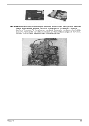
the mylar is a mylar on the main board (see the highlighted with red below; Because the main board mylar should be stuck to the main board to the replacement main board. Chapter 3 58 The short could cause the main board or the antenna cable burned. IMPORTANT:When assembling/disassembling the main board, whenever there is sami-transparent, film-like stuff ), it should be transferred "if necessary" to prevent the antenna cable and the main board components short circuit.
the mylar is a mylar on the main board (see the highlighted with red below; Because the main board mylar should be stuck to the main board to the replacement main board. Chapter 3 58 The short could cause the main board or the antenna cable burned. IMPORTANT:When assembling/disassembling the main board, whenever there is sami-transparent, film-like stuff ), it should be transferred "if necessary" to prevent the antenna cable and the main board components short circuit.

Acer Aspire 1640 Service Guide
Page 63
... remove it. 5. Remove the four screws holding the right bracket. 11. Then remove the right bracket. 12. Remove one screw that tighten the left hinge. 7. Disassembling the LCD Module 1. Remove the two screws holding the LCD bezel. 3. Remove the three screws holding the LCD bracket on the other side. 9. Then remove...
... remove it. 5. Remove the four screws holding the right bracket. 11. Then remove the right bracket. 12. Remove one screw that tighten the left hinge. 7. Disassembling the LCD Module 1. Remove the two screws holding the LCD bezel. 3. Remove the three screws holding the LCD bracket on the other side. 9. Then remove...
Acer Aspire 1640 Service Guide
Page 65
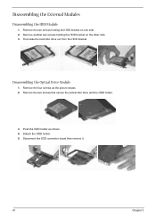
Remove the two screws holding the HDD bracket on one side. 2. Remove the four screws as shown. 4. Disconnect the ODD connector board then remove it. 61 Chapter 3 Then take the hard disc drive out from the HDD bracket. Remove the two screws that secure the optical disc drive and the ODD holder. 3. Push the ODD holder as the picture shows. 2. Disassembling the External Modules Disassembling the HDD Module 1. Detach the ODD holder. 5. Remove another two screws holding the HDD bracket on the other side. 3. Disassembling the Optical Drive Module 1.
Remove the two screws holding the HDD bracket on one side. 2. Remove the four screws as shown. 4. Disconnect the ODD connector board then remove it. 61 Chapter 3 Then take the hard disc drive out from the HDD bracket. Remove the two screws that secure the optical disc drive and the ODD holder. 3. Push the ODD holder as the picture shows. 2. Disassembling the External Modules Disassembling the HDD Module 1. Detach the ODD holder. 5. Remove another two screws holding the HDD bracket on the other side. 3. Disassembling the Optical Drive Module 1.

Aspire 1640 User's Guide
Page 72
... the fuse rating. 9 Never push objects of any kind onto or into the extension cord does not exceed the extension cord ampere rating. Do not disassemble or dispose of fire or explosion. 13 Warning! Also, make sure that the total ampere rating of the equipment plugged into the product. 10 Do...) for service. 12 The notebook PC series uses lithium batteries. b If liquid has been spilled into this product from the wall outlet before serving or disassembling this equipment. 17 Avoid using a telephone (other risks.
... the fuse rating. 9 Never push objects of any kind onto or into the extension cord does not exceed the extension cord ampere rating. Do not disassemble or dispose of fire or explosion. 13 Warning! Also, make sure that the total ampere rating of the equipment plugged into the product. 10 Do...) for service. 12 The notebook PC series uses lithium batteries. b If liquid has been spilled into this product from the wall outlet before serving or disassembling this equipment. 17 Avoid using a telephone (other risks.
Aspire 1640 User's Guide
Page 73
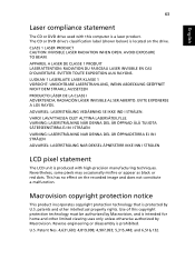
... is produced with this copyright protection technology must be authorized by Macrovision, and is a laser product. LAVATTAESSA OLET ALTTINA LASERSÅTEILYLLE. Reverse engineering or disassembly is located on the recorded image and does not constitute a malfunction. AVOID EXPOSURE TO BEAM. Nevertheless, some pixels may occasionally misfire or appear as black...
... is produced with this copyright protection technology must be authorized by Macrovision, and is a laser product. LAVATTAESSA OLET ALTTINA LASERSÅTEILYLLE. Reverse engineering or disassembly is located on the recorded image and does not constitute a malfunction. AVOID EXPOSURE TO BEAM. Nevertheless, some pixels may occasionally misfire or appear as black...


