
User Manual
Page 3
... 1.6 I/O Panel 14 2 Installation 16 2.1 Screw Holes 16 2.2 Pre-installation Precautions 16 2.3 CPU Installation 17 2.4 Installation of Heatsink and CPU fan 19 2.5 Installation of Memory Modules (DIMM 20 2.6 Expansion Slots (PCI and PCI Express Slots 22 2.7 SLITM and Quad SLITM Operation Guide 23 ...Quad CrossFireXTM Operation Guide 27 2.9 Surround Display Feature 32 2.10 Jumpers Setup 32 2.11 Onboard Headers and Connectors 33 2.12 Smart Switches 39 2.13 Dr. Debug 40 2.14 HDMI_SPDIF Header Connection Guide 43 2.15 Serial ATA (SATA) / Serial ATAII (SATAII) Hard Disks Installation 44...
... 1.6 I/O Panel 14 2 Installation 16 2.1 Screw Holes 16 2.2 Pre-installation Precautions 16 2.3 CPU Installation 17 2.4 Installation of Heatsink and CPU fan 19 2.5 Installation of Memory Modules (DIMM 20 2.6 Expansion Slots (PCI and PCI Express Slots 22 2.7 SLITM and Quad SLITM Operation Guide 23 ...Quad CrossFireXTM Operation Guide 27 2.9 Surround Display Feature 32 2.10 Jumpers Setup 32 2.11 Onboard Headers and Connectors 33 2.12 Smart Switches 39 2.13 Dr. Debug 40 2.14 HDMI_SPDIF Header Connection Guide 43 2.15 Serial ATA (SATA) / Serial ATAII (SATAII) Hard Disks Installation 44...
User Manual
Page 7
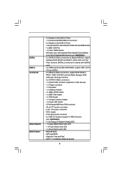
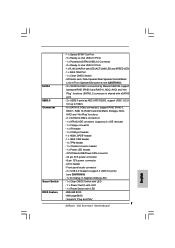
... (SATA3_2 connector is shared with LED - 8Mb AMI BIOS - AMI Legal BIOS - HD Audio Jack: Side Speaker/Rear Speaker/Central/Bass/ Line in header - CPU/Chassis/NB/Power FAN connector - 24 pin ATX power connector - 8 pin 12V power connector - CD in /Front Speaker/Microphone (see CAUTION 6) - 1 x Dr....), NCQ, AHCI and "Hot Plug" functions - 2 x SATA3 6.0Gb/s connectors - 1 x ATA133 IDE connector (supports 2 x IDE devices) - 1 x Floppy connector - 1 x IR header - 1 x COM port header - 1 x HDMI_SPDIF header - 1 x IEEE 1394 header - 1 x TPM header - 1 x Chassis Intrusion header - 1 x Power LED...
... (SATA3_2 connector is shared with LED - 8Mb AMI BIOS - AMI Legal BIOS - HD Audio Jack: Side Speaker/Rear Speaker/Central/Bass/ Line in header - CPU/Chassis/NB/Power FAN connector - 24 pin ATX power connector - 8 pin 12V power connector - CD in /Front Speaker/Microphone (see CAUTION 6) - 1 x Dr....), NCQ, AHCI and "Hot Plug" functions - 2 x SATA3 6.0Gb/s connectors - 1 x ATA133 IDE connector (supports 2 x IDE devices) - 1 x Floppy connector - 1 x IR header - 1 x COM port header - 1 x HDMI_SPDIF header - 1 x IEEE 1394 header - 1 x TPM header - 1 x Chassis Intrusion header - 1 x Power LED...
User Manual
Page 13
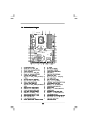
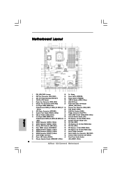
... Super I/O CI1 1 IR1 1 HDMI_SPDIF1 1 FLOPPY1 NEC USB 3.0 SATA3 6Gb/s IDE1 PCIE1 QPI 6.4GT/s PCIE2 PCI Express 2.0 PCI1 X58 Extreme3 8Mb BIOS 1394a CMOS Battery CLRCMOS1 1 PCIE3 ErP/EuP Ready PCI2 VIA VT6308S Intel ICH10R RoHS PCIE4 COM1 1 1 TPM1 FRONT_1394 CHA_FAN1 1...Power Connector (ATX12V1) 24 Power Switch (PWRBTN) 4 1366-Pin CPU Socket 25 USB 2.0 Header (USB6_7, Blue) 5 Power Fan Connector (PWR_FAN1) 26 8Mb SPI Flash 6 Chassis Fan Connector (CHA_FAN2) 27 Front Panel IEEE 1394 Header 7 3 x 240-pin DDR3 DIMM Slots (FRONT_1394, White) (Triple Channel: DDR3_A1, ...
... Super I/O CI1 1 IR1 1 HDMI_SPDIF1 1 FLOPPY1 NEC USB 3.0 SATA3 6Gb/s IDE1 PCIE1 QPI 6.4GT/s PCIE2 PCI Express 2.0 PCI1 X58 Extreme3 8Mb BIOS 1394a CMOS Battery CLRCMOS1 1 PCIE3 ErP/EuP Ready PCI2 VIA VT6308S Intel ICH10R RoHS PCIE4 COM1 1 1 TPM1 FRONT_1394 CHA_FAN1 1...Power Connector (ATX12V1) 24 Power Switch (PWRBTN) 4 1366-Pin CPU Socket 25 USB 2.0 Header (USB6_7, Blue) 5 Power Fan Connector (PWR_FAN1) 26 8Mb SPI Flash 6 Chassis Fan Connector (CHA_FAN2) 27 Front Panel IEEE 1394 Header 7 3 x 240-pin DDR3 DIMM Slots (FRONT_1394, White) (Triple Channel: DDR3_A1, ...

User Manual
Page 19
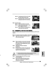
... heatsink. Below is equipped with 1366-Pin socket that the CPU and the heatsink are oriented on side closest to the CPU fan connector on the motherboard (CPU_FAN1, see page 13, No. 2). Apply thermal interface material onto center of IHS on fastener caps with thumb ... you need to spray thermal interface material between the CPU and the heatsink to the CPU_FAN connector (CPU_FAN1, see page 13, No. 2). Connect fan header with fan operation or contact other . Step 1. Secure excess cable with tie-wrap to dissipate heat. Ensure that supports Intel 1366-Pin CPU. Repeat with ...
... heatsink. Below is equipped with 1366-Pin socket that the CPU and the heatsink are oriented on side closest to the CPU fan connector on the motherboard (CPU_FAN1, see page 13, No. 2). Apply thermal interface material onto center of IHS on fastener caps with thumb ... you need to spray thermal interface material between the CPU and the heatsink to the CPU_FAN connector (CPU_FAN1, see page 13, No. 2). Connect fan header with fan operation or contact other . Step 1. Secure excess cable with tie-wrap to dissipate heat. Ensure that supports Intel 1366-Pin CPU. Repeat with ...

User Manual
Page 36
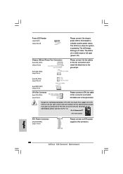
... and match the black wire to this connector. 36 Pin 1-3 Connected 3-Pin Fan Installation ATX Power Connector (24-pin ATXPWR1) (see p.13, No. 8) 12 24 1 13 Please connect an ATX power supply to the ground pin. Power LED Header (3-pin PLED1) (see p.13 No. 20) 1 PLEDPLED+ PLED+ Please ...connect the chassis power LED to this header to Pin 1-3. If you plan to connect the 3-Pin CPU fan to the CPU fan connector on when the system is operating. Though this motherboard, please connect it to indicate system power status. The...
... and match the black wire to this connector. 36 Pin 1-3 Connected 3-Pin Fan Installation ATX Power Connector (24-pin ATXPWR1) (see p.13, No. 8) 12 24 1 13 Please connect an ATX power supply to the ground pin. Power LED Header (3-pin PLED1) (see p.13 No. 20) 1 PLEDPLED+ PLED+ Please ...connect the chassis power LED to this header to Pin 1-3. If you plan to connect the 3-Pin CPU fan to the CPU fan connector on when the system is operating. Though this motherboard, please connect it to indicate system power status. The...
User Manual
Page 43
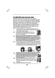
...pin) (C) Step 4. To use HDMI function on the motherboard. A complete HDMI system requires a HDMI VGA card and a HDMI ready motherboard with a HDMI_SPDIF header, which provides an interface between any compatible digital audio/ video source, such as a set-top box, DVD player, A/V receiver and a compatible digital audio ...HDMI VGA card to the VGA card user manual for detailed connection procedures. Please choose the appropriate white end according to the fan connector of the HDMI VGA card you install. Otherwise, the motherboard and the VGA card may cause permanent damage to the ...
...pin) (C) Step 4. To use HDMI function on the motherboard. A complete HDMI system requires a HDMI VGA card and a HDMI ready motherboard with a HDMI_SPDIF header, which provides an interface between any compatible digital audio/ video source, such as a set-top box, DVD player, A/V receiver and a compatible digital audio ...HDMI VGA card to the VGA card user manual for detailed connection procedures. Please choose the appropriate white end according to the fan connector of the HDMI VGA card you install. Otherwise, the motherboard and the VGA card may cause permanent damage to the ...
Quick Installation Guide
Page 2
... 2.0 x16 Slot (PCIE1, Blue) 17 SATAII Connector (SATAII_3_4, Blue) 41 North Bridge Controller 18 SATAII Connector (SATAII_5_6, Blue) 42 North Bridge Fan Connector (NB_FAN1) 19 South Bridge Controller 43 Internal Audio Connector: CD1 (Black) 20 Power LED Header (PLED1) 44 Front Panel Audio Header 21 Chassis Speaker Header (SPEAKER 1, White) (HD_AUDIO1, White) 2 ASRock X58 Extreme3 Motherboard English
... 2.0 x16 Slot (PCIE1, Blue) 17 SATAII Connector (SATAII_3_4, Blue) 41 North Bridge Controller 18 SATAII Connector (SATAII_5_6, Blue) 42 North Bridge Fan Connector (NB_FAN1) 19 South Bridge Controller 43 Internal Audio Connector: CD1 (Black) 20 Power LED Header (PLED1) 44 Front Panel Audio Header 21 Chassis Speaker Header (SPEAKER 1, White) (HD_AUDIO1, White) 2 ASRock X58 Extreme3 Motherboard English
Quick Installation Guide
Page 7
... - 1 x RJ-45 LAN Port with LED - 8Mb AMI BIOS - Supports "Plug and Play" 7 ASRock X58 Extreme3 Motherboard English CPU/Chassis/NB/Power FAN connector - 24 pin ATX power connector - 8 pin 12V power connector - AMI Legal BIOS - SATA3 USB3.0... 6.0Gb/s connectors - 1 x ATA133 IDE connector (supports 2 x IDE devices) - 1 x Floppy connector - 1 x IR header - 1 x COM port header - 1 x HDMI_SPDIF header - 1 x IEEE 1394 header - 1 x TPM header - 1 x Chassis Intrusion header - 1 x Power LED header - CD in /Front Speaker/Microphone (see CAUTION 6) - 1 x Dr. Debug (7-Segment Debug LED) - 1 x Clear CMOS...
... - 1 x RJ-45 LAN Port with LED - 8Mb AMI BIOS - Supports "Plug and Play" 7 ASRock X58 Extreme3 Motherboard English CPU/Chassis/NB/Power FAN connector - 24 pin ATX power connector - 8 pin 12V power connector - AMI Legal BIOS - SATA3 USB3.0... 6.0Gb/s connectors - 1 x ATA133 IDE connector (supports 2 x IDE devices) - 1 x Floppy connector - 1 x IR header - 1 x COM port header - 1 x HDMI_SPDIF header - 1 x IEEE 1394 header - 1 x TPM header - 1 x Chassis Intrusion header - 1 x Power LED header - CD in /Front Speaker/Microphone (see CAUTION 6) - 1 x Dr. Debug (7-Segment Debug LED) - 1 x Clear CMOS...
Quick Installation Guide
Page 15
...Rotate the fastener clockwise, then press down on fastener caps with the CPU fan connector on load plate, engage the load lever. Connect fan header with thumb to illustrate the installation of CPU Fan and Heatsink For proper installation, please kindly refer to the orient keys. Step... with the motherboard throughholes. Ensure fan cables are oriented on the socket surface. Step 6. Align fasteners with fan operation or contact other components. 15 ASRock X58 Extreme3 Motherboard English Secure excess cable with tie-wrap to the CPU fan connector on the motherboard. While...
...Rotate the fastener clockwise, then press down on fastener caps with the CPU fan connector on load plate, engage the load lever. Connect fan header with thumb to illustrate the installation of CPU Fan and Heatsink For proper installation, please kindly refer to the orient keys. Step... with the motherboard throughholes. Ensure fan cables are oriented on the socket surface. Step 6. Align fasteners with fan operation or contact other components. 15 ASRock X58 Extreme3 Motherboard English Secure excess cable with tie-wrap to the CPU fan connector on the motherboard. While...
Quick Installation Guide
Page 30
..., please connect it to Pin 1-3. If you plan to connect the 3-Pin CPU fan to the CPU fan connector on when the system is off ). Power LED Header (3-pin PLED1) (see p.2 No. 20) Chassis, NB and Power Fan Connectors (4-pin CHA_FAN1) (see p.2 No. 28) (3-pin CHA_FAN2) (see p.2 No...fan cables to the fan connectors and match the black wire to the ground pin. (3-pin NB_FAN1) (see p.2 No. 42) (3-pin PWR_FAN1) (see p.2 No. 5) CPU Fan Connector (4-pin CPU_FAN1) (see p.2, No. 8) 12 24 1 13 Please connect an ATX power supply to this header to the ground pin. English 30 ASRock X58 Extreme3...
..., please connect it to Pin 1-3. If you plan to connect the 3-Pin CPU fan to the CPU fan connector on when the system is off ). Power LED Header (3-pin PLED1) (see p.2 No. 20) Chassis, NB and Power Fan Connectors (4-pin CHA_FAN1) (see p.2 No. 28) (3-pin CHA_FAN2) (see p.2 No...fan cables to the fan connectors and match the black wire to the ground pin. (3-pin NB_FAN1) (see p.2 No. 42) (3-pin PWR_FAN1) (see p.2 No. 5) CPU Fan Connector (4-pin CPU_FAN1) (see p.2, No. 8) 12 24 1 13 Please connect an ATX power supply to this header to the ground pin. English 30 ASRock X58 Extreme3...


