User Manual
Page 4
... RAID Functions 54 2.22.2 Installing Windows® 7 / 7 64-bit / VistaTM / VistaTM 64-bit Without RAID Functions 53 2.23 Untied Overclocking Technology 53 3 BIOS SETUP UTILITY 54 3.1 Introduction 54 3.1.1 BIOS Menu Bar 54 3.1.2 Navigation Keys 55 3.2 Main Screen 55 3.3 OC Tweaker Screen 56 3.4 Advanced Screen 60 3.4.1 CPU Configuration 61 3.4.2 Chipset Configuration 63 3.4.3 ACPI...
... RAID Functions 54 2.22.2 Installing Windows® 7 / 7 64-bit / VistaTM / VistaTM 64-bit Without RAID Functions 53 2.23 Untied Overclocking Technology 53 3 BIOS SETUP UTILITY 54 3.1 Introduction 54 3.1.1 BIOS Menu Bar 54 3.1.2 Navigation Keys 55 3.2 Main Screen 55 3.3 OC Tweaker Screen 56 3.4 Advanced Screen 60 3.4.1 CPU Configuration 61 3.4.2 Chipset Configuration 63 3.4.3 ACPI...
User Manual
Page 5
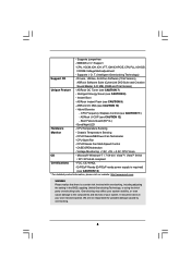
... occur, the updated version will be available on ASRock website as well. ASRock website http://www.asrock.com If you require technical support related to BIOS setup and information of this motherboard, please visit our...) ASRock X58 Extreme3 Quick Installation Guide ASRock X58 Extreme3 Support CD 1 x 80-conductor Ultra ATA 66/100/133 IDE Ribbon Cable 1 x Ribbon Cable for purchasing ASRock X58 Extreme3 motherboard, a reliable motherboard produced under ASRock's consistently stringent quality control. www.asrock.com/support/index.asp 1.1 Package Contents ASRock X58 Extreme3 Motherboard...
... occur, the updated version will be available on ASRock website as well. ASRock website http://www.asrock.com If you require technical support related to BIOS setup and information of this motherboard, please visit our...) ASRock X58 Extreme3 Quick Installation Guide ASRock X58 Extreme3 Support CD 1 x 80-conductor Ultra ATA 66/100/133 IDE Ribbon Cable 1 x Ribbon Cable for purchasing ASRock X58 Extreme3 motherboard, a reliable motherboard produced under ASRock's consistently stringent quality control. www.asrock.com/support/index.asp 1.1 Package Contents ASRock X58 Extreme3 Motherboard...
User Manual
Page 7
.../Chassis/NB/Power FAN connector - 24 pin ATX power connector - 8 pin 12V power connector - SATA3 USB3.0 Connector Smart Switch BIOS Feature - 5 x Ready-to-Use USB 2.0 Ports - 1 x Powered eSATAIII/USB 2.0 Connector - 2 x Ready-to 5Gb/s - 6 x SATAII 3.0Gb/s connectors, support RAID (RAID 0,... eSATA3 port) - 2 x USB3.0 ports by NEC UPD720200, support USB 1.0/2.0/ 3.0 up to -Use USB 3.0 Ports - 1 x RJ-45 LAN Port with LED - 8Mb AMI BIOS - ACPI 1.1 Compliance Wake Up Events 7 CD in /Front Speaker/Microphone (see CAUTION 6) - 1 x Dr. Debug (7-Segment Debug LED) - 1 x Clear CMOS Switch with LED...
.../Chassis/NB/Power FAN connector - 24 pin ATX power connector - 8 pin 12V power connector - SATA3 USB3.0 Connector Smart Switch BIOS Feature - 5 x Ready-to-Use USB 2.0 Ports - 1 x Powered eSATAIII/USB 2.0 Connector - 2 x Ready-to 5Gb/s - 6 x SATAII 3.0Gb/s connectors, support RAID (RAID 0,... eSATA3 port) - 2 x USB3.0 ports by NEC UPD720200, support USB 1.0/2.0/ 3.0 up to -Use USB 3.0 Ports - 1 x RJ-45 LAN Port with LED - 8Mb AMI BIOS - ACPI 1.1 Compliance Wake Up Events 7 CD in /Front Speaker/Microphone (see CAUTION 6) - 1 x Dr. Debug (7-Segment Debug LED) - 1 x Clear CMOS Switch with LED...
User Manual
Page 8
...responsible for possible damage caused by overclocking. 8 T. (Intelligent Overclocking Technology) Support CD - ASRock Instant Flash (see CAUTION 11) - CPU Frequency Stepless Control (see CAUTION 9) - Chassis Temperature Sensing - ASRock OC DNA (see CAUTION 8) - CPU Temperature Sensing Monitor - Microsoft® Windows®... information, please visit our website: http://www.asrock.com WARNING Please realize that there is a certain risk involved with overclocking, including adjusting the setting in the BIOS, applying Untied Overclocking Technology, or using the ...
...responsible for possible damage caused by overclocking. 8 T. (Intelligent Overclocking Technology) Support CD - ASRock Instant Flash (see CAUTION 11) - CPU Frequency Stepless Control (see CAUTION 9) - Chassis Temperature Sensing - ASRock OC DNA (see CAUTION 8) - CPU Temperature Sensing Monitor - Microsoft® Windows®... information, please visit our website: http://www.asrock.com WARNING Please realize that there is a certain risk involved with overclocking, including adjusting the setting in the BIOS, applying Untied Overclocking Technology, or using the ...
User Manual
Page 9
...hardware devices to the operating system limitation, the actual memory size may be noted that delivers unparalleled power savings. ASRock Instant Flash is a BIOS flash utility embedded in a few clicks without preparing an additional floppy diskette or other words, it is a...works fine under Windows® environment. In other complicated flash utility. This convenient BIOS update tool allows you implement Triple Channel Memory Technology, make sure to access ASRock Instant Flash. This motherboard supports Untied Overclocking Technology. Before you to provide exceptional ...
...hardware devices to the operating system limitation, the actual memory size may be noted that delivers unparalleled power savings. ASRock Instant Flash is a BIOS flash utility embedded in a few clicks without preparing an additional floppy diskette or other words, it is a...works fine under Windows® environment. In other complicated flash utility. This convenient BIOS update tool allows you implement Triple Channel Memory Technology, make sure to access ASRock Instant Flash. This motherboard supports Untied Overclocking Technology. Before you to provide exceptional ...
User Manual
Page 13
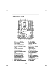
... Designed in Taipei LAN PHY AUDIO CODEC Super I/O CI1 1 IR1 1 HDMI_SPDIF1 1 FLOPPY1 NEC USB 3.0 SATA3 6Gb/s IDE1 PCIE1 QPI 6.4GT/s PCIE2 PCI Express 2.0 PCI1 X58 Extreme3 8Mb BIOS 1394a CMOS Battery CLRCMOS1 1 PCIE3 ErP/EuP Ready PCI2 VIA VT6308S Intel ICH10R RoHS PCIE4 COM1 1 1 TPM1 FRONT_1394 CHA_FAN1 1 USB6_7 1 PWRBTN RSTBTN Debug LED PLED1...
... Designed in Taipei LAN PHY AUDIO CODEC Super I/O CI1 1 IR1 1 HDMI_SPDIF1 1 FLOPPY1 NEC USB 3.0 SATA3 6Gb/s IDE1 PCIE1 QPI 6.4GT/s PCIE2 PCI Express 2.0 PCI1 X58 Extreme3 8Mb BIOS 1394a CMOS Battery CLRCMOS1 1 PCIE3 ErP/EuP Ready PCI2 VIA VT6308S Intel ICH10R RoHS PCIE4 COM1 1 1 TPM1 FRONT_1394 CHA_FAN1 1 USB6_7 1 PWRBTN RSTBTN Debug LED PLED1...
User Manual
Page 32
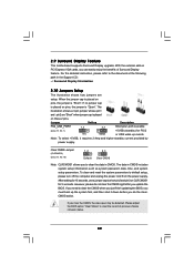
...Clear CMOS Jumper (CLRCMOS1) (see p.13, No. 1) 2_3 Short pin2, pin3 to clear the record of Surround Display feature. If you update the BIOS. Please adjust the BIOS option "Clear Status" to enable +5VSB (standby) for 5 seconds. Note: To select +5VSB, it down before you must boot up events. After ...waiting for 15 seconds, use a jumper cap to clear the CMOS when you just finish updating the BIOS, you do not clear the CMOS right after you clear the CMOS, the case open may be detected. 2.9 Surround Display Feature This motherboard ...
...Clear CMOS Jumper (CLRCMOS1) (see p.13, No. 1) 2_3 Short pin2, pin3 to clear the record of Surround Display feature. If you update the BIOS. Please adjust the BIOS option "Clear Status" to enable +5VSB (standby) for 5 seconds. Note: To select +5VSB, it down before you must boot up events. After ...waiting for 15 seconds, use a jumper cap to clear the CMOS when you just finish updating the BIOS, you do not clear the CMOS right after you clear the CMOS, the case open may be detected. 2.9 Surround Display Feature This motherboard ...

User Manual
Page 35
... SPEAKER 1) (see p.13 No. 21) 1 SPEAKER DUMMY DUMMY +5V Please connect the chassis speaker to Ground (GND). B. Connect Ground (GND) to this header. 35 Enter BIOS Setup Utility. This connector allows you use AC'97 audio panel, please install it to [Enabled]. Please follow the instruction in our manual and chassis...
... SPEAKER 1) (see p.13 No. 21) 1 SPEAKER DUMMY DUMMY +5V Please connect the chassis speaker to Ground (GND). B. Connect Ground (GND) to this header. 35 Enter BIOS Setup Utility. This connector allows you use AC'97 audio panel, please install it to [Enabled]. Please follow the instruction in our manual and chassis...

User Manual
Page 40
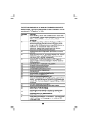
...Description Early chipset initialization is available. The Runtime module is stored in PMM. CPUID information is uncompressed into memory. Copying Main BIOS into memory. The Bootblock initialization code sets up from ROM to lower system memory and control is forced. Verify the bootblock ... 512KB memory. NMI is enabled. Re-enable CACHE. Restore CPUID value back into register. Perform keyboard controller BAT test. Main BIOS checksum is checked to execute serial flash. Do additional chipset initialization. Please see the diagrams below 1MB Read-Write including E000 and...
...Description Early chipset initialization is available. The Runtime module is stored in PMM. CPUID information is uncompressed into memory. Copying Main BIOS into memory. The Bootblock initialization code sets up from ROM to lower system memory and control is forced. Verify the bootblock ... 512KB memory. NMI is enabled. Re-enable CACHE. Restore CPUID value back into register. Perform keyboard controller BAT test. Main BIOS checksum is checked to execute serial flash. Do additional chipset initialization. Please see the diagrams below 1MB Read-Write including E000 and...
User Manual
Page 41
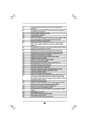
...compatible PICs in KBC port. Program the keyboard controller command byte is bad, update CMOS with power-on KBC. Detects the presence of the BIOS: Checkpoint 03 04 05 06 08 C0 C1 C2 C5 C6 C7 0A 0B 0C 0E 13 24 30 2A 2C 2E 31 Description ... the largest set up application proccessors Re-enable cache for initialization. Install the POSTINT1Ch handler. Uncompress all the output devices. Initialize BIOS, POST, Runtime data area. Also initialize BIOS modules on CMOS setup questions. Initialize CH-0 as mentioned in the system that the POST INT09h handler gets control for ADM....
...compatible PICs in KBC port. Program the keyboard controller command byte is bad, update CMOS with power-on KBC. Detects the presence of the BIOS: Checkpoint 03 04 05 06 08 C0 C1 C2 C5 C6 C7 0A 0B 0C 0E 13 24 30 2A 2C 2E 31 Description ... the largest set up application proccessors Re-enable cache for initialization. Install the POSTINT1Ch handler. Uncompress all the output devices. Initialize BIOS, POST, Runtime data area. Also initialize BIOS modules on CMOS setup questions. Initialize CH-0 as mentioned in the system that the POST INT09h handler gets control for ADM....
User Manual
Page 42
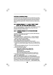
...Log errors encountered during POST. 85 Display errors to OS. Prepares the runtime language module. A9 Wait for error. 87 Execute BIOS setup if needed / requested. 8C Late POST initialization of system management interrupt. Enable/Disable NMI as selected 90 Late POST ...information. 38 Initializes different devices through DIM. 39 Initializes DMAC-1 & DMAC-2. 3A Initialize RTC date/time. 3B Test for different BIOS modules. B1 Save system context for displaying text information. 37 Displaying sign-on message, CPU information, setup key message, and ...
...Log errors encountered during POST. 85 Display errors to OS. Prepares the runtime language module. A9 Wait for error. 87 Execute BIOS setup if needed / requested. 8C Late POST initialization of system management interrupt. Enable/Disable NMI as selected 90 Late POST ...information. 38 Initializes different devices through DIM. 39 Initializes DMAC-1 & DMAC-2. 3A Initialize RTC date/time. 3B Test for different BIOS modules. B1 Save system context for displaying text information. 37 Displaying sign-on message, CPU information, setup key message, and ...
User Manual
Page 48
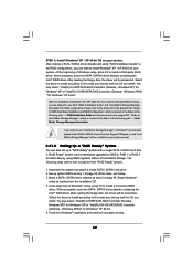
STEP 1: Set up to bottom side to format and copy files [YN]? Enter BIOS SETUP UTILITY Advanced screen Storage Configuration. A. D. Then you will see the message on the screen, "Do you want to install Windows® XP / XP 64-... steps. Therefore, the drivers you see these messages, Please insert a diskette into your SATA / SATAII HDDs with RAID functions, please follow the order from up BIOS. The system will lose ALL data in the Support CD, "Guide to generate Serial ATA driver diskette [YN]?", press . STEP 2: Make a SATA / SATAII Driver Diskette...
STEP 1: Set up to bottom side to format and copy files [YN]? Enter BIOS SETUP UTILITY Advanced screen Storage Configuration. A. D. Then you will see the message on the screen, "Do you want to install Windows® XP / XP 64-... steps. Therefore, the drivers you see these messages, Please insert a diskette into your SATA / SATAII HDDs with RAID functions, please follow the order from up BIOS. The system will lose ALL data in the Support CD, "Guide to generate Serial ATA driver diskette [YN]?", press . STEP 2: Make a SATA / SATAII Driver Diskette...
User Manual
Page 49
...(R) ICH10R SATA RAID Controller (Desktop - After reading the floppy disk, the driver will be presented. Select the driver to install according to set up system BIOS as step 2 of page 48. Windows XP)" for Windows® XP 64-bit. 5. Make a SATA / SATAII driver diskette as step 1 of page 48. STEP 4: Install...
...(R) ICH10R SATA RAID Controller (Desktop - After reading the floppy disk, the driver will be presented. Select the driver to install according to set up system BIOS as step 2 of page 48. Windows XP)" for Windows® XP 64-bit. 5. Make a SATA / SATAII driver diskette as step 1 of page 48. STEP 4: Install...
User Manual
Page 51
Enter BIOS SETUP UTILITY Advanced screen Storage Configuration. Please refer to the document in the Support CD, "Guide to SATA Hard Disks Installation and RAID Configuration", which ...: .. \ RAID Installation Guide STEP 3: Install Windows® 7 / 7 64-bit / VistaTM / VistaTM 64-bit OS on your system as ", please set RAID configuration. STEP 1: Set up BIOS. Set "SATAII Configuration" to [Enhanced], and then in the folder at the following path: .. \ Intel Matrix Storage Manager Information If you want to use both...
Enter BIOS SETUP UTILITY Advanced screen Storage Configuration. Please refer to the document in the Support CD, "Guide to SATA Hard Disks Installation and RAID Configuration", which ...: .. \ RAID Installation Guide STEP 3: Install Windows® 7 / 7 64-bit / VistaTM / VistaTM 64-bit OS on your system as ", please set RAID configuration. STEP 1: Set up BIOS. Set "SATAII Configuration" to [Enhanced], and then in the folder at the following path: .. \ Intel Matrix Storage Manager Information If you want to use both...

User Manual
Page 52
...Configure SATAII as ", please set the option to [IDE]. STEP 2: Install Windows® XP / XP 64-bit OS on your system. Enter BIOS SETUP UTILITY Advanced screen Storage Configuration. Set "SATAII Configuration" to [Enhanced], and then in the option "Configure SATAII as ", please set the ... the driver to install according to install a third-party AHCI driver. Using SATA / SATAII HDDs and eSATA3 devices without NCQ function STEP 1: Set up BIOS. STEP 3: Install Windows® XP / XP 64-bit OS on your system. 52 A. Please make a SATA / SATAII driver diskette by following section...
...Configure SATAII as ", please set the option to [IDE]. STEP 2: Install Windows® XP / XP 64-bit OS on your system. Enter BIOS SETUP UTILITY Advanced screen Storage Configuration. Set "SATAII Configuration" to [Enhanced], and then in the option "Configure SATAII as ", please set the ... the driver to install according to install a third-party AHCI driver. Using SATA / SATAII HDDs and eSATA3 devices without NCQ function STEP 1: Set up BIOS. STEP 3: Install Windows® XP / XP 64-bit OS on your system. 52 A. Please make a SATA / SATAII driver diskette by following section...
User Manual
Page 53
... in the option "Configure SATAII as ", please set the option to the warning on your SATA / SATAII HDDs without NCQ function STEP 1: Set up BIOS. STEP 2: Install Windows® 7 / 7 64-bit / VistaTM / VistaTM 64-bit OS on your system. 2.23 Untied Overclocking Technology This motherboard... / VistaTM 64-bit OS on page 8 for the possible overclocking risk before you enable Untied Overclocking function, please enter "Overclock Mode" option of BIOS setup to set the option to [Manual]. B. Please refer to [IDE]. B. Using SATA / SATAII HDDs and eSATA3 devices without RAID functions, ...
... in the option "Configure SATAII as ", please set the option to the warning on your SATA / SATAII HDDs without NCQ function STEP 1: Set up BIOS. STEP 2: Install Windows® 7 / 7 64-bit / VistaTM / VistaTM 64-bit OS on your system. 2.23 Untied Overclocking Technology This motherboard... / VistaTM 64-bit OS on page 8 for the possible overclocking risk before you enable Untied Overclocking function, please enter "Overclock Mode" option of BIOS setup to set the option to [Manual]. B. Please refer to [IDE]. B. Using SATA / SATAII HDDs and eSATA3 devices without RAID functions, ...
User Manual
Page 54
..., and they may also restart by pressing the reset button on your system. Chapter 3: BIOS SETUP UTILITY 3.1 Introduction This section explains how to use the BIOS SETUP UTILITY to configure your screen. 3.1.1 BIOS Menu Bar The top of the screen has a menu bar with its test routines. Because... selections: Main To set up the system time/date information OC Tweaker To set up overclocking features Advanced To set up the advanced BIOS features H/W Monitor To display current hardware status Boot To set up the default system device to locate and load the Operating System Security...
..., and they may also restart by pressing the reset button on your system. Chapter 3: BIOS SETUP UTILITY 3.1 Introduction This section explains how to use the BIOS SETUP UTILITY to configure your screen. 3.1.1 BIOS Menu Bar The top of the screen has a menu bar with its test routines. Because... selections: Main To set up the system time/date information OC Tweaker To set up overclocking features Advanced To set up the advanced BIOS features H/W Monitor To display current hardware status Boot To set up the default system device to locate and load the Operating System Security...

User Manual
Page 55
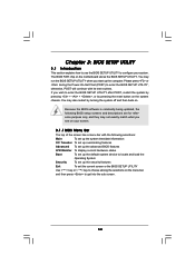
... UTILITY To jump to the Exit Screen or exit the current screen 3.2 Main Screen When you enter the BIOS SETUP UTILITY, the Main screen will appear and display the system overview. Use [+] or [-] to select a field. Navigation Key(s) / / + / Function Description ... UTILITY Main OC Tweaker Advanced H/W Monitor Boot Security Exit System Overview System Time System Date [14:00:09] [Tue 02/09/2010] BIOS Version : X58 Extreme3 P1.00 Processor Type : Intel (R) CPU 000 @ 3.20GHz (64bit) Processor Speed : 3200MHz Microcode Update : 106A4/10 Cache Size : 8192KB Total Memory DDR3_A2...
... UTILITY To jump to the Exit Screen or exit the current screen 3.2 Main Screen When you enter the BIOS SETUP UTILITY, the Main screen will appear and display the system overview. Use [+] or [-] to select a field. Navigation Key(s) / / + / Function Description ... UTILITY Main OC Tweaker Advanced H/W Monitor Boot Security Exit System Overview System Time System Date [14:00:09] [Tue 02/09/2010] BIOS Version : X58 Extreme3 P1.00 Processor Type : Intel (R) CPU 000 @ 3.20GHz (64bit) Processor Speed : 3200MHz Microcode Update : 106A4/10 Cache Size : 8192KB Total Memory DDR3_A2...
User Manual
Page 56
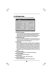
... You can use this option to page 53 for the details of Untied Overclocking Technology. It should be done at your own risk and expense. BIOS SETUP UTILITY Main OC Tweaker Advanced H/W Monitor Boot Security Exit OC Tweaker Settings Load CPU EZ OC Setting Load DDR3 EZ OC Setting [Press Enter...
... You can use this option to page 53 for the details of Untied Overclocking Technology. It should be done at your own risk and expense. BIOS SETUP UTILITY Main OC Tweaker Advanced H/W Monitor Boot Security Exit OC Tweaker Settings Load CPU EZ OC Setting Load DDR3 EZ OC Setting [Press Enter...

User Manual
Page 57
...(s) inserted and assigns appropriate frequency automatically. For exanple, if the DRAM frequency is unlocked, you changing the ratio value of memory accessing. DRAM Timing Control BIOS SETUP UTILITY Advanced DRAM Timing Control Current Setting : 7-7-7-20-59-8-4-4-4-20 DRAM tCL [Auto] DRAM tRCD [Auto] DRAM tRP [Auto] DRAM tRAS DRAM tRFC DRAM...
...(s) inserted and assigns appropriate frequency automatically. For exanple, if the DRAM frequency is unlocked, you changing the ratio value of memory accessing. DRAM Timing Control BIOS SETUP UTILITY Advanced DRAM Timing Control Current Setting : 7-7-7-20-59-8-4-4-4-20 DRAM tCL [Auto] DRAM tRCD [Auto] DRAM tRP [Auto] DRAM tRAS DRAM tRFC DRAM...


