User Manual
Page 9
... and save the new BIOS file to your USB flash drive, floppy disk or hard drive, then you implement Triple Channel Memory Technology, make sure to provide exceptional power saving and improve power efficiency without entering operating systems first like MS-DOS or Windows®. This motherboard supports Untied Overclocking Technology. This motherboard supports Triple Channel Memory Technology. In other complicated flash utility. For Windows® OS with 64-bit CPU, there is able to read "Untied Overclocking Technology" on page 53...
... and save the new BIOS file to your USB flash drive, floppy disk or hard drive, then you implement Triple Channel Memory Technology, make sure to provide exceptional power saving and improve power efficiency without entering operating systems first like MS-DOS or Windows®. This motherboard supports Untied Overclocking Technology. This motherboard supports Triple Channel Memory Technology. In other complicated flash utility. For Windows® OS with 64-bit CPU, there is able to read "Untied Overclocking Technology" on page 53...
User Manual
Page 13
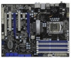
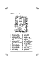
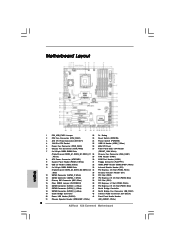
... Fan Connector (NB_FAN1) 19 South Bridge Controller 43 Internal Audio Connector: CD1 (Black) 20 Power LED Header (PLED1) 44 Front Panel Audio Header 21 Chassis Speaker Header (SPEAKER 1, White) (HD_AUDIO1, White) 13 1.5 Motherboard Layout 123 45 6 7 24.4cm (9.6 in) Six-Core CPU Ready 1 PS2_USB_PWR1 ATX12V1 PWR_FAN1 CHA_FAN2 8 CPU_FAN1 PS2 Mouse PS2 Keyboard Clr CMOS 30.5cm (12.0 in) ATXPWR1 Coaxial SPDIF Optical SPDIF PANEL1 PLED PWRBTN 1 HDLED RESET DDR3_C1 (64 bit, 240-pin module) DDR3_C2 (64 bit, 240-pin...
... Fan Connector (NB_FAN1) 19 South Bridge Controller 43 Internal Audio Connector: CD1 (Black) 20 Power LED Header (PLED1) 44 Front Panel Audio Header 21 Chassis Speaker Header (SPEAKER 1, White) (HD_AUDIO1, White) 13 1.5 Motherboard Layout 123 45 6 7 24.4cm (9.6 in) Six-Core CPU Ready 1 PS2_USB_PWR1 ATX12V1 PWR_FAN1 CHA_FAN2 8 CPU_FAN1 PS2 Mouse PS2 Keyboard Clr CMOS 30.5cm (12.0 in) ATXPWR1 Coaxial SPDIF Optical SPDIF PANEL1 PLED PWRBTN 1 HDLED RESET DDR3_C1 (64 bit, 240-pin module) DDR3_C2 (64 bit, 240-pin...

User Manual
Page 29
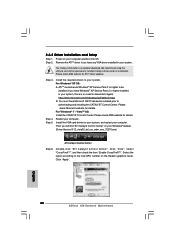
... CATALYST Control Center. Install the VGA card drivers to your Windows® taskbar. (Driver Version: 8-12_vista32_dd_ccc_wdm_enu_72275.exe) ATI Catalyst Control Center 29 Power on your system. Step 4. Then you have Windows® XP Service Pack 2 or higher installed in your computer and boot into OS. ATITM recommends Windows® XP Service Pack 2 or higher to downloading and installing the CATALYST Control Center. Step 5. Restart your system, there is an optional download...
... CATALYST Control Center. Install the VGA card drivers to your Windows® taskbar. (Driver Version: 8-12_vista32_dd_ccc_wdm_enu_72275.exe) ATI Catalyst Control Center 29 Power on your system. Step 4. Then you have Windows® XP Service Pack 2 or higher installed in your computer and boot into OS. ATITM recommends Windows® XP Service Pack 2 or higher to downloading and installing the CATALYST Control Center. Step 5. Restart your system, there is an optional download...
User Manual
Page 42
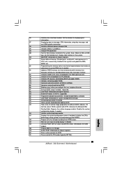
... at config display if needed before boot, which includes the programming of chipset registers. 8D Build ACPI tables (if ACPI is supported) 8E Program the peripheral parameters. AC End of POST initialization of system management interrupt. Deinitializes the ADM module. Display total memory in the system. 3C Mid POST initialization of chipset registers. 40 Detect different devices (Parallel ports, serial ports, and coprocessor in CPU, etc.) successfully installed...
... at config display if needed before boot, which includes the programming of chipset registers. 8D Build ACPI tables (if ACPI is supported) 8E Program the peripheral parameters. AC End of POST initialization of system management interrupt. Deinitializes the ADM module. Display total memory in the system. 3C Mid POST initialization of chipset registers. 40 Detect different devices (Parallel ports, serial ports, and coprocessor in CPU, etc.) successfully installed...
User Manual
Page 43
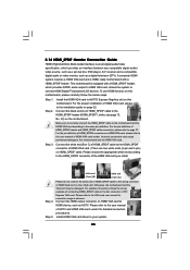
...; PCI Express Graphics slot on HDMI VGA card to HDMI device, such as a digital television (DTV). For the proper installation of HDMI VGA card, please refer to the installation guide on HDMI VGA card, please refer to the user manual of HDMI_SPDIF connectors on page 22. For the pin definition of HDMI VGA card vendor. A complete HDMI system requires a HDMI VGA card and a HDMI ready motherboard with a HDMI_SPDIF header, which provides an interface between any compatible digital audio/ video source, such as a set-top box, DVD player...
...; PCI Express Graphics slot on HDMI VGA card to HDMI device, such as a digital television (DTV). For the proper installation of HDMI VGA card, please refer to the installation guide on HDMI VGA card, please refer to the user manual of HDMI_SPDIF connectors on page 22. For the pin definition of HDMI VGA card vendor. A complete HDMI system requires a HDMI VGA card and a HDMI ready motherboard with a HDMI_SPDIF header, which provides an interface between any compatible digital audio/ video source, such as a set-top box, DVD player...
User Manual
Page 48
... drivers compatible to your system. B. Please select CD-ROM as ", please set RAID configuration. C. WARNING! The system will see the message on the screen, "Do you want to generate Serial ATA driver diskette [YN]?", press . STEP 3: Use "RAID Installation Guide" to set the option to [RAID]. Before you start to format the floppy diskette and copy SATA / SATAII drivers into the floppy drive, and press . Enter BIOS SETUP UTILITY Advanced screen Storage Configuration. Insert the Support CD into the floppy drive. During POST...
... drivers compatible to your system. B. Please select CD-ROM as ", please set RAID configuration. C. WARNING! The system will see the message on the screen, "Do you want to generate Serial ATA driver diskette [YN]?", press . STEP 3: Use "RAID Installation Guide" to set the option to [RAID]. Before you start to format the floppy diskette and copy SATA / SATAII drivers into the floppy drive, and press . Enter BIOS SETUP UTILITY Advanced screen Storage Configuration. Insert the Support CD into the floppy drive. During POST...
User Manual
Page 49
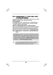
... 64-bit OS on your system. After reading the floppy disk, the driver will be presented. You may select: "Intel(R) ICH10R SATA RAID Controller (Desktop Windows XP)" for Windows® XP or "Intel(R) ICH10R SATA RAID Controller (Desktop - Windows XP64) " for Windows® XP or "Intel(R) ICH10R SATA RAID Controller (Desktop - Please refer to the document in the Support CD, "Guide to SATA Hard Disks Installation and RAID Configuration", which is located in the folder at the following path: .. \ RAID Installation Guide...
... 64-bit OS on your system. After reading the floppy disk, the driver will be presented. You may select: "Intel(R) ICH10R SATA RAID Controller (Desktop Windows XP)" for Windows® XP or "Intel(R) ICH10R SATA RAID Controller (Desktop - Windows XP64) " for Windows® XP or "Intel(R) ICH10R SATA RAID Controller (Desktop - Please refer to the document in the Support CD, "Guide to SATA Hard Disks Installation and RAID Configuration", which is located in the folder at the following path: .. \ RAID Installation Guide...
User Manual
Page 51
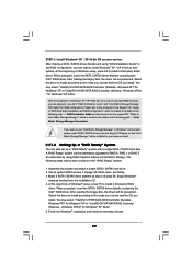
... is located in Windows® environment, please install SATA / SATAII drivers from the Support CD again so that "Intel Matrix Storage Manager" will be installed to use both "RAID Installation Guide" and "Intel Matrix Storage Manager Information" for proper configuration. Enter BIOS SETUP UTILITY Advanced screen Storage Configuration. Please refer to the document in the Support CD, "Guide to check the installation guide in the option "Configure SATAII as well. 51 A. After the installation of Windows® 7 / 7 64-bit / VistaTM...
... is located in Windows® environment, please install SATA / SATAII drivers from the Support CD again so that "Intel Matrix Storage Manager" will be installed to use both "RAID Installation Guide" and "Intel Matrix Storage Manager Information" for proper configuration. Enter BIOS SETUP UTILITY Advanced screen Storage Configuration. Please refer to the document in the Support CD, "Guide to check the installation guide in the option "Configure SATAII as well. 51 A. After the installation of Windows® 7 / 7 64-bit / VistaTM...
User Manual
Page 61
... Unlocked (Min:12, Max:20) Ratio Actual Value 20 CPU Ratio Setting Enhanced Halt State Intel (R) Virtualization tech. CPU Thermal Throttling No-Excute Memory Protection Intel (R) HT Technology Active Processor Cores A20M Intel (R) SpeedStep(tm) tech Intel (R) TurboMode tech [Auto] [Disabled] [Enabled] [Enabled] [Disabled] [Enabled] [All] [Disabled] [Enabled] [Enabled] Select the ration between CPU Core Clock and the FSB Frequency. +F1 F9 F10 ESC Select Screen Select Item Change Option General Help Load Defaults Save and Exit...
... Unlocked (Min:12, Max:20) Ratio Actual Value 20 CPU Ratio Setting Enhanced Halt State Intel (R) Virtualization tech. CPU Thermal Throttling No-Excute Memory Protection Intel (R) HT Technology Active Processor Cores A20M Intel (R) SpeedStep(tm) tech Intel (R) TurboMode tech [Auto] [Disabled] [Enabled] [Enabled] [Disabled] [Enabled] [All] [Disabled] [Enabled] [Enabled] Select the ration between CPU Core Clock and the FSB Frequency. +F1 F9 F10 ESC Select Screen Select Item Change Option General Help Load Defaults Save and Exit...

User Manual
Page 66
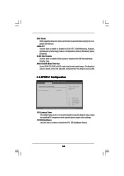
If you select [RAID] or [AHCI] mode, the options "Hot Plug" and "SATA Link Power Management" will improve SATA disk performance but IDE mode does not have these advantages. Configuration mode: [IDE] and [AHCI]. The default value is [IDE]. The default value is [IDE]. The default value is installed, please select [Enhanced]. AHCI (Advanced Host Controller Interface) supports NCQ and other new features that will appear. Compatible Mode Use this item to build RAID for Marvell SATA3 ports. If native...
If you select [RAID] or [AHCI] mode, the options "Hot Plug" and "SATA Link Power Management" will improve SATA disk performance but IDE mode does not have these advantages. Configuration mode: [IDE] and [AHCI]. The default value is [IDE]. The default value is [IDE]. The default value is installed, please select [Enhanced]. AHCI (Advanced Host Controller Interface) supports NCQ and other new features that will appear. Compatible Mode Use this item to build RAID for Marvell SATA3 ports. If native...
User Manual
Page 68
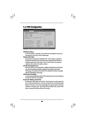
.../DVD Boot Time Out Some SATA CD / DVD in units of PCI clocks for compatible IDE devices. Configuration options: [Disabled], [Auto], [Enabled]. 32-Bit Data Transfer Use this item to enable 32-bit access to wait ready longer. Configuration options: [0], [5], [10], [15], [20], [25], [30] and [35]. It is recommended to enable or disable the S.M.A.R.T. (Self-Monitoring, Analysis, and Reporting Technology) feature. The default value is 32. Use this item to enable or disable the PCI IDE BusMaster feature. 68 DMA Mode...
.../DVD Boot Time Out Some SATA CD / DVD in units of PCI clocks for compatible IDE devices. Configuration options: [Disabled], [Auto], [Enabled]. 32-Bit Data Transfer Use this item to enable 32-bit access to wait ready longer. Configuration options: [0], [5], [10], [15], [20], [25], [30] and [35]. It is recommended to enable or disable the S.M.A.R.T. (Self-Monitoring, Analysis, and Reporting Technology) feature. The default value is 32. Use this item to enable or disable the PCI IDE BusMaster feature. 68 DMA Mode...

User Manual
Page 70
... 2.0 Support Use this item to select legacy support for USB devices. USB devices are not allowed to enter OS. [BIOS Setup Only] - There are connected. [Disabled] - 3.4.8USB Configuration BIOS SETUP UTILITY Advanced USB Configuration USB Controller USB 2.0 Support Legacy USB Support Onboard USB3 [Enabled] [Enabled] [Enabled] [Enabled] To enable or disable the onboard USB controllers. +F1 F9 F10 ESC Select Screen Select Item Change Option General Help Load Defaults Save and Exit Exit v02.54 (C) Copyright 1985-2005, American Megatrends, Inc. If you have USB compatibility...
... 2.0 Support Use this item to select legacy support for USB devices. USB devices are not allowed to enter OS. [BIOS Setup Only] - There are connected. [Disabled] - 3.4.8USB Configuration BIOS SETUP UTILITY Advanced USB Configuration USB Controller USB 2.0 Support Legacy USB Support Onboard USB3 [Enabled] [Enabled] [Enabled] [Enabled] To enable or disable the onboard USB controllers. +F1 F9 F10 ESC Select Screen Select Item Change Option General Help Load Defaults Save and Exit Exit v02.54 (C) Copyright 1985-2005, American Megatrends, Inc. If you have USB compatibility...
User Manual
Page 73
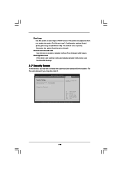
Configuration options: [Auto], [EuP], [Scenery] and [ASRock X58]. Currently, the option [Auto] is set to [On], it . Boot From Onboard LAN Use this option to select logo in POST screen. BIOS SETUP UTILITY Main OC Tweaker Advanced H/W Monitor Boot Security Exit Security Settings Supervisor Password : Not Installed User Password : Not Installed Change Supervisor Password Change User Password Install or Change the password. Boot Up Num-Lock If this section, you may also clear it will automatically activate the Numeric Lock function after boot-up. 3.7 Security Screen In this ...
Configuration options: [Auto], [EuP], [Scenery] and [ASRock X58]. Currently, the option [Auto] is set to [On], it . Boot From Onboard LAN Use this option to select logo in POST screen. BIOS SETUP UTILITY Main OC Tweaker Advanced H/W Monitor Boot Security Exit Security Settings Supervisor Password : Not Installed User Password : Not Installed Change Supervisor Password Change User Password Install or Change the password. Boot Up Num-Lock If this section, you may also clear it will automatically activate the Numeric Lock function after boot-up. 3.7 Security Screen In this ...
User Manual
Page 75
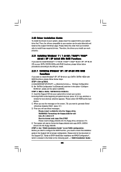
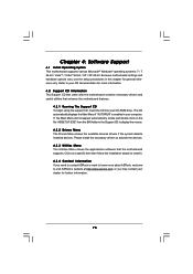
... Main Menu if "AUTORUN" is enabled in this chapter for general reference only. Chapter 4: Software Support 4.1 Install Operating System This motherboard supports various Microsoft® Windows® operating systems: 7 / 7 64-bit / VistaTM / VistaTM 64-bit / XP / XP 64-bit. Please install the necessary drivers to display the menus. 4.2.2 Drivers Menu The Drivers Menu shows the available devices drivers if the system detects installed devices. Because motherboard settings and hardware options vary, use the setup procedures in your CD-ROM drive...
... Main Menu if "AUTORUN" is enabled in this chapter for general reference only. Chapter 4: Software Support 4.1 Install Operating System This motherboard supports various Microsoft® Windows® operating systems: 7 / 7 64-bit / VistaTM / VistaTM 64-bit / XP / XP 64-bit. Please install the necessary drivers to display the menus. 4.2.2 Drivers Menu The Drivers Menu shows the available devices drivers if the system detects installed devices. Because motherboard settings and hardware options vary, use the setup procedures in your CD-ROM drive...
Quick Installation Guide
Page 2
...20 Power LED Header (PLED1) 44 Front Panel Audio Header 21 Chassis Speaker Header (SPEAKER 1, White) (HD_AUDIO1, White) 2 ASRock X58 Extreme3 Motherboard English Motherboard Layout 1 PS2_USB_PWR1 Jumper 22 Dr. Debug 2 CPU Fan Connector (CPU_FAN1) 23 Reset Switch (RSTBTN) 3 ATX 12V Power Connector (ATX12V1) 24 Power Switch (PWRBTN) 4 1366-Pin CPU Socket 25 USB 2.0 Header (USB6_7, Blue) 5 Power Fan Connector (PWR_FAN1) 26 8Mb SPI Flash 6 Chassis Fan Connector (CHA_FAN2) 27 Front Panel IEEE 1394 Header 7 3 x 240-pin DDR3 DIMM Slots (FRONT_1394, White) (Triple Channel: DDR3_A1...
...20 Power LED Header (PLED1) 44 Front Panel Audio Header 21 Chassis Speaker Header (SPEAKER 1, White) (HD_AUDIO1, White) 2 ASRock X58 Extreme3 Motherboard English Motherboard Layout 1 PS2_USB_PWR1 Jumper 22 Dr. Debug 2 CPU Fan Connector (CPU_FAN1) 23 Reset Switch (RSTBTN) 3 ATX 12V Power Connector (ATX12V1) 24 Power Switch (PWRBTN) 4 1366-Pin CPU Socket 25 USB 2.0 Header (USB6_7, Blue) 5 Power Fan Connector (PWR_FAN1) 26 8Mb SPI Flash 6 Chassis Fan Connector (CHA_FAN2) 27 Front Panel IEEE 1394 Header 7 3 x 240-pin DDR3 DIMM Slots (FRONT_1394, White) (Triple Channel: DDR3_A1...
Quick Installation Guide
Page 9
... limitation, the actual memory size may be noted that delivers unparalleled power savings. Please be less than 4GB for the reservation for proper installation. 4. About the setting of "Hyper Threading Technology", please check page 62 of "User Manual" in Flash ROM. For Windows® OS with 64-bit CPU, there is a revolutionary technology that the USB flash drive or hard drive must use FAT32/16/12 file system. 9 ASRock X58 Extreme3 Motherboard English Please visit...
... limitation, the actual memory size may be noted that delivers unparalleled power savings. Please be less than 4GB for the reservation for proper installation. 4. About the setting of "Hyper Threading Technology", please check page 62 of "User Manual" in Flash ROM. For Windows® OS with 64-bit CPU, there is a revolutionary technology that the USB flash drive or hard drive must use FAT32/16/12 file system. 9 ASRock X58 Extreme3 Motherboard English Please visit...
Quick Installation Guide
Page 24
... Control Center Step 6. Click "Apply". 2.6.2 Driver Installation and Setup Step 1. For Windows® XP OS: A. English 24 ASRock X58 Extreme3 Motherboard Remove the ATITM driver if you will find "ATI Catalyst Control Center" on your computer. Step 4. Select the option according to installation. Step 3. You must have any previously installed Catalyst drivers prior to the total GPU number on your computer and boot into OS. Install the VGA card drivers to download...
... Control Center Step 6. Click "Apply". 2.6.2 Driver Installation and Setup Step 1. For Windows® XP OS: A. English 24 ASRock X58 Extreme3 Motherboard Remove the ATITM driver if you will find "ATI Catalyst Control Center" on your computer. Step 4. Select the option according to installation. Step 3. You must have any previously installed Catalyst drivers prior to the total GPU number on your computer and boot into OS. Install the VGA card drivers to download...
Quick Installation Guide
Page 35
... chipset registers. 8D Build ACPI tables (if ACPI is supported) 8E Program the peripheral parameters. A9 Wait for error. 87 Execute BIOS setup if needed . AA Uninstall POST INT1Ch vector and INT09h vector. English 35 ASRock X58 Extreme3 Motherboard A1 Clean-up work needed . A7 Displays the system configuration screen if enabled. Deinitializes the ADM module. AB Prepare BBS for OS boot including final MTRR values. Disables the system configuration display...
... chipset registers. 8D Build ACPI tables (if ACPI is supported) 8E Program the peripheral parameters. A9 Wait for error. 87 Execute BIOS setup if needed . AA Uninstall POST INT1Ch vector and INT09h vector. English 35 ASRock X58 Extreme3 Motherboard A1 Clean-up work needed . A7 Displays the system configuration screen if enabled. Deinitializes the ADM module. AB Prepare BBS for OS boot including final MTRR values. Disables the system configuration display...
Quick Installation Guide
Page 38
... system chassis. To begin using the Support CD, insert the CD into your computer. It will enhance motherboard features. Software Support CD information This motherboard supports various Microsoft® Windows® operating systems: 7 / 7 64-bit / VistaTM / VistaTM 64-bit / XP / XP 64-bit. otherwise, POST continues with the motherboard contains necessary drivers and useful utilities that will display the Main Menu automatically if "AUTORUN" is designed to display the menus. 38 ASRock X58 Extreme3 Motherboard...
... system chassis. To begin using the Support CD, insert the CD into your computer. It will enhance motherboard features. Software Support CD information This motherboard supports various Microsoft® Windows® operating systems: 7 / 7 64-bit / VistaTM / VistaTM 64-bit / XP / XP 64-bit. otherwise, POST continues with the motherboard contains necessary drivers and useful utilities that will display the Main Menu automatically if "AUTORUN" is designed to display the menus. 38 ASRock X58 Extreme3 Motherboard...
RAID Installation Guide
Page 7
.... After reading the floppy disk, the driver will be installed to install a third-party RAID driver. Please refer to the document in the Support CD, "Guide to SATA Hard Disks Installation and RAID Configuration", which is located in the folder at the following path: .. \ Intel Matrix Storage Information If you want to manage RAID functions, you install. 5. At the beginning of Windows setup, press F6 to the mode you choose and the...
.... After reading the floppy disk, the driver will be installed to install a third-party RAID driver. Please refer to the document in the Support CD, "Guide to SATA Hard Disks Installation and RAID Configuration", which is located in the folder at the following path: .. \ Intel Matrix Storage Information If you want to manage RAID functions, you install. 5. At the beginning of Windows setup, press F6 to the mode you choose and the...


