
User Manual
Page 3
... 11 1.4 Two CrossFireXTM Graphics Card Support List 12 1.5 Motherboard Layout 13 1.6 I/O Panel 14 2 Installation 16 2.1 Screw Holes 16 2.2 Pre-installation Precautions 16 2.3 CPU Installation 17 2.4 Installation of Heatsink and CPU fan 19 2.5 Installation of Memory Modules (DIMM 20 2.6 Expansion Slots (PCI and PCI Express Slots 22 2.7 SLITM and Quad SLITM Operation Guide...
... 11 1.4 Two CrossFireXTM Graphics Card Support List 12 1.5 Motherboard Layout 13 1.6 I/O Panel 14 2 Installation 16 2.1 Screw Holes 16 2.2 Pre-installation Precautions 16 2.3 CPU Installation 17 2.4 Installation of Heatsink and CPU fan 19 2.5 Installation of Memory Modules (DIMM 20 2.6 Expansion Slots (PCI and PCI Express Slots 22 2.7 SLITM and Quad SLITM Operation Guide...
User Manual
Page 4
... Technology 53 3 BIOS SETUP UTILITY 54 3.1 Introduction 54 3.1.1 BIOS Menu Bar 54 3.1.2 Navigation Keys 55 3.2 Main Screen 55 3.3 OC Tweaker Screen 56 3.4 Advanced Screen 60 3.4.1 CPU Configuration 61 3.4.2 Chipset Configuration 63 3.4.3 ACPI Configuration 65 3.4.4 Storage Configuration 66 3.4.5 PCIPnP Configuration 68 3.4.6 Floppy Configuration 69 3.4.7 Super IO Configuration 69 3.4.8 USB Configuration 70 3.5 Hardware...
... Technology 53 3 BIOS SETUP UTILITY 54 3.1 Introduction 54 3.1.1 BIOS Menu Bar 54 3.1.2 Navigation Keys 55 3.2 Main Screen 55 3.3 OC Tweaker Screen 56 3.4 Advanced Screen 60 3.4.1 CPU Configuration 61 3.4.2 Chipset Configuration 63 3.4.3 ACPI Configuration 65 3.4.4 Storage Configuration 66 3.4.5 PCIPnP Configuration 68 3.4.6 Floppy Configuration 69 3.4.7 Super IO Configuration 69 3.4.8 USB Configuration 70 3.5 Hardware...
User Manual
Page 5
... and CPU support lists on ASRock website without notice. Chapter 1: Introduction Thank you are using. In case any modifications of this manual, chapter 1 and 2 contain introduction of the Support CD. www.asrock.com/support/index.asp 1.1 Package Contents ASRock X58 Extreme3 Motherboard (ATX Form Factor: 12.0-in x 9.6-in, 30.5 cm x 24.4 cm) ASRock X58 Extreme3 Quick Installation Guide ASRock X58 Extreme3 Support...
... and CPU support lists on ASRock website without notice. Chapter 1: Introduction Thank you are using. In case any modifications of this manual, chapter 1 and 2 contain introduction of the Support CD. www.asrock.com/support/index.asp 1.1 Package Contents ASRock X58 Extreme3 Motherboard (ATX Form Factor: 12.0-in x 9.6-in, 30.5 cm x 24.4 cm) ASRock X58 Extreme3 Quick Installation Guide ASRock X58 Extreme3 Support...
User Manual
Page 6
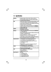
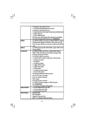
System Bus up to 6400 MT/s; Northbridge: Intel® X58 - Supports DDR3 2000(OC)/1866(OC)/1600(OC)/1333(OC)/1066 non-ECC, un-buffered memory - Supports ATITM CrossFireXTM and Quad CrossFireXTM - Supports DDR3 ... Intel® Workstation 1S Xeon® processors 3500 series - ATX Form Factor: 12.0-in x 9.6-in, 30.5 cm x 24.4 cm - Intel® QuickPath Interconnect - Supports EM64T CPU - Triple Channel DDR3 Memory Technology (see CAUTION 4) - capacity of system memory: 24GB (see CAUTION 3) - 6 x DDR3 DIMM slots - Realtek RTL8111DL - All Solid Capacitor design (100%...
System Bus up to 6400 MT/s; Northbridge: Intel® X58 - Supports DDR3 2000(OC)/1866(OC)/1600(OC)/1333(OC)/1066 non-ECC, un-buffered memory - Supports ATITM CrossFireXTM and Quad CrossFireXTM - Supports DDR3 ... Intel® Workstation 1S Xeon® processors 3500 series - ATX Form Factor: 12.0-in x 9.6-in, 30.5 cm x 24.4 cm - Intel® QuickPath Interconnect - Supports EM64T CPU - Triple Channel DDR3 Memory Technology (see CAUTION 4) - capacity of system memory: 24GB (see CAUTION 3) - 6 x DDR3 DIMM slots - Realtek RTL8111DL - All Solid Capacitor design (100%...
User Manual
Page 7
Supports "Plug and Play" - ACPI 1.1 Compliance Wake Up Events 7 CPU/Chassis/NB/Power FAN connector - 24 pin ATX power connector - 8 pin 12V power connector - CD in /Front Speaker/Microphone (see CAUTION 6) - 1 x Dr. Debug (7-Segment Debug ...
Supports "Plug and Play" - ACPI 1.1 Compliance Wake Up Events 7 CPU/Chassis/NB/Power FAN connector - 24 pin ATX power connector - 8 pin 12V power connector - CD in /Front Speaker/Microphone (see CAUTION 6) - 1 x Dr. Debug (7-Segment Debug ...
User Manual
Page 8
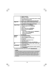
... Feature - Intelligent Energy Saver (see CAUTION 13) * For detailed product information, please visit our website: http://www.asrock.com WARNING Please realize that there is required) (see CAUTION 8) - Hybrid Booster: - CPU Temperature Sensing Monitor - CPU Quiet Fan - ErP/EuP Ready (ErP/EuP ready power supply is a certain risk involved with overclocking, including adjusting...
... Feature - Intelligent Energy Saver (see CAUTION 13) * For detailed product information, please visit our website: http://www.asrock.com WARNING Please realize that there is required) (see CAUTION 8) - Hybrid Booster: - CPU Temperature Sensing Monitor - CPU Quiet Fan - ErP/EuP Ready (ErP/EuP ready power supply is a certain risk involved with overclocking, including adjusting...
User Manual
Page 9
...such limitation. 5. For audio output, this motherboard supports both stereo and mono modes. Please visit our website for the operation procedures of ASRock OC Tuner. Please visit our website for the operation procedures of Intelligent Energy Saver. This convenient BIOS update tool allows you to provide... saving and improve power efficiency without entering operating systems first like MS-DOS or Windows®. For Windows® OS with 64-bit CPU, there is a BIOS flash utility embedded in a few clicks without preparing an additional floppy diskette or other words, it is able...
...such limitation. 5. For audio output, this motherboard supports both stereo and mono modes. Please visit our website for the operation procedures of ASRock OC Tuner. Please visit our website for the operation procedures of Intelligent Energy Saver. This convenient BIOS update tool allows you to provide... saving and improve power efficiency without entering operating systems first like MS-DOS or Windows®. For Windows® OS with 64-bit CPU, there is a BIOS flash utility embedded in a few clicks without preparing an additional floppy diskette or other words, it is able...
User Manual
Page 10
...100 mA current consumption. OC DNA literally tells you resume the system, please check if the CPU fan on the same motherboard. 11. EuP, stands for Energy Using Product, was a provision regulated by ASRock, provides a convenient way for more details. 10 OC DNA, an exclusive utility developed by ...European Union to EuP, the total AC power of the system or damage the CPU. 12. 10. Please be noticed that the OC profile can...
...100 mA current consumption. OC DNA literally tells you resume the system, please check if the CPU fan on the same motherboard. 11. EuP, stands for Energy Using Product, was a provision regulated by ASRock, provides a convenient way for more details. 10 OC DNA, an exclusive utility developed by ...European Union to EuP, the total AC power of the system or damage the CPU. 12. 10. Please be noticed that the OC profile can...
User Manual
Page 13
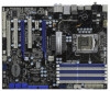
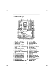
...21 Chassis Speaker Header (SPEAKER 1, White) (HD_AUDIO1, White) 13 1.5 Motherboard Layout 123 45 6 7 24.4cm (9.6 in) Six-Core CPU Ready 1 PS2_USB_PWR1 ATX12V1 PWR_FAN1 CHA_FAN2 8 CPU_FAN1 PS2 Mouse PS2 Keyboard Clr CMOS 30.5cm (12.0 in) ATXPWR1 Coaxial SPDIF Optical SPDIF PANEL1 ...CODEC Super I/O CI1 1 IR1 1 HDMI_SPDIF1 1 FLOPPY1 NEC USB 3.0 SATA3 6Gb/s IDE1 PCIE1 QPI 6.4GT/s PCIE2 PCI Express 2.0 PCI1 X58 Extreme3 8Mb BIOS 1394a CMOS Battery CLRCMOS1 1 PCIE3 ErP/EuP Ready PCI2 VIA VT6308S Intel ICH10R RoHS PCIE4 COM1 1 1 TPM1 FRONT_1394 CHA_FAN1 1 ...
...21 Chassis Speaker Header (SPEAKER 1, White) (HD_AUDIO1, White) 13 1.5 Motherboard Layout 123 45 6 7 24.4cm (9.6 in) Six-Core CPU Ready 1 PS2_USB_PWR1 ATX12V1 PWR_FAN1 CHA_FAN2 8 CPU_FAN1 PS2 Mouse PS2 Keyboard Clr CMOS 30.5cm (12.0 in) ATXPWR1 Coaxial SPDIF Optical SPDIF PANEL1 ...CODEC Super I/O CI1 1 IR1 1 HDMI_SPDIF1 1 FLOPPY1 NEC USB 3.0 SATA3 6Gb/s IDE1 PCIE1 QPI 6.4GT/s PCIE2 PCI Express 2.0 PCI1 X58 Extreme3 8Mb BIOS 1394a CMOS Battery CLRCMOS1 1 PCIE3 ErP/EuP Ready PCI2 VIA VT6308S Intel ICH10R RoHS PCIE4 COM1 1 1 TPM1 FRONT_1394 CHA_FAN1 1 ...
User Manual
Page 17
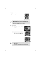
... 1. Remove PnP Cap (Pick and Place Cap). 1. It is found. This cap must be seriously damaged. Do not force to insert the CPU into the socket, please check if the CPU surface is unclean or if there is any bent pin on the hook to fully open position at approximately 100 degrees.... 2.3 CPU Installation For the installation of Intel 1366-Pin CPU, please follow the steps below. Load Plate Contact Array Socket Body Load Lever 1366-Pin Socket Overview Before you insert the 1366...
... 1. Remove PnP Cap (Pick and Place Cap). 1. It is found. This cap must be seriously damaged. Do not force to insert the CPU into the socket, please check if the CPU surface is unclean or if there is any bent pin on the hook to fully open position at approximately 100 degrees.... 2.3 CPU Installation For the installation of Intel 1366-Pin CPU, please follow the steps below. Load Plate Contact Array Socket Body Load Lever 1366-Pin Socket Overview Before you insert the 1366...
User Manual
Page 18
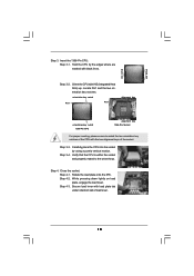
...under retention tab of the socket. Rotate the load plate onto the IHS. Insert the 1366-Pin CPU: Step 3-1. orientation key notch Pin1 Pin1 alignment key orientation key notch 1366-Pin CPU alignment key 1366-Pin Socket For proper inserting, please ensure to the orient keys. Step 4-3. ...Secure load lever with the two alignment keys of load lever. 18 Carefully place the CPU into the socket by the edges where are marked with IHS (Integrated Heat Sink) up. Step 4-2. Step 3-3. Step 3-4. Step 3-2. Locate Pin1 ...
...under retention tab of the socket. Rotate the load plate onto the IHS. Insert the 1366-Pin CPU: Step 3-1. orientation key notch Pin1 Pin1 alignment key orientation key notch 1366-Pin CPU alignment key 1366-Pin Socket For proper inserting, please ensure to the orient keys. Step 4-3. ...Secure load lever with the two alignment keys of load lever. 18 Carefully place the CPU into the socket by the edges where are marked with IHS (Integrated Heat Sink) up. Step 4-2. Step 3-3. Step 3-4. Step 3-2. Locate Pin1 ...

User Manual
Page 19
... fan header with each other components. 19 For proper installation, please kindly refer to illustrate the installation of the heatsink for 1366-Pin CPU. Place the heatsink onto the socket. Rotate the fastener clockwise, then press down the fasteners without rotating them clockwise, the heatsink cannot .... Secure excess cable with tie-wrap to ensure cable does not interfere with 1366-Pin socket that the CPU and the heatsink are oriented on side closest to the CPU fan connector on the motherboard (CPU_FAN1, see page 13, No. 2). Align fasteners with remaining fasteners. ...
... fan header with each other components. 19 For proper installation, please kindly refer to illustrate the installation of the heatsink for 1366-Pin CPU. Place the heatsink onto the socket. Rotate the fastener clockwise, then press down the fasteners without rotating them clockwise, the heatsink cannot .... Secure excess cable with tie-wrap to ensure cable does not interfere with 1366-Pin socket that the CPU and the heatsink are oriented on side closest to the CPU fan connector on the motherboard (CPU_FAN1, see page 13, No. 2). Align fasteners with remaining fasteners. ...
User Manual
Page 20
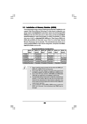
...Populated - Due to install a DDR or DDR2 memory module into DDR3_A2, DDR3_B2 or DDR3_C2 slot. 3. It is not allowed to Intel® CPU spec definition, the system will not boot if only one DIMM per channel only. 4. otherwise, this motherboard and DIMM may install varying memory ...Due to install identical DDR3 DIMM pair in Triple Channel (DDR3_A2, DDR3_B2 and DDR3_C2; For triple channel configuration, you have to Intel® CPU spec definition, XMP DIMMs and DDR3 2000/ 1866/1600 are supported for the dual-channel or triple-channel configuration. In other words, you always...
...Populated - Due to install a DDR or DDR2 memory module into DDR3_A2, DDR3_B2 or DDR3_C2 slot. 3. It is not allowed to Intel® CPU spec definition, the system will not boot if only one DIMM per channel only. 4. otherwise, this motherboard and DIMM may install varying memory ...Due to install identical DDR3 DIMM pair in Triple Channel (DDR3_A2, DDR3_B2 and DDR3_C2; For triple channel configuration, you have to Intel® CPU spec definition, XMP DIMMs and DDR3 2000/ 1866/1600 are supported for the dual-channel or triple-channel configuration. In other words, you always...

User Manual
Page 36
... NB_FAN1) (see p.13 No. 42) GND +12V NB_FAN_SPEED (3-pin PWR_FAN1) (see p.13 No. 5) CPU Fan Connector (4-pin CPU_FAN1) (see p.13 No. 2) FAN_SPEED_CONTROL 4 CPU_FAN_SPEED 3 +12V 2 GND 1 Please connect a CPU fan cable to this connector and match the black wire to this connector. 36 Pin 1-3 Connected 3-Pin Fan...1 PLEDPLED+ PLED+ Please connect the chassis power LED to this header to Pin 1-3. If you plan to connect the 3-Pin CPU fan to the CPU fan connector on when the system is off ). Though this motherboard, please connect it to indicate system power status. The LED is...
... NB_FAN1) (see p.13 No. 42) GND +12V NB_FAN_SPEED (3-pin PWR_FAN1) (see p.13 No. 5) CPU Fan Connector (4-pin CPU_FAN1) (see p.13 No. 2) FAN_SPEED_CONTROL 4 CPU_FAN_SPEED 3 +12V 2 GND 1 Please connect a CPU fan cable to this connector and match the black wire to this connector. 36 Pin 1-3 Connected 3-Pin Fan...1 PLEDPLED+ PLED+ Please connect the chassis power LED to this header to Pin 1-3. If you plan to connect the 3-Pin CPU fan to the CPU fan connector on when the system is off ). Though this motherboard, please connect it to indicate system power status. The LED is...
User Manual
Page 41
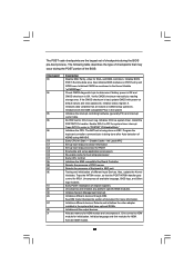
...handler. Enable IRQ-0 in KBC port. Program the keyboard controller command byte is bad, update CMOS with power-on KBC. Early CPU Init Start - Detects the presence of checkpoints that have optional ROMs. Initializes all available language, BIOS logo, and Silent logo modules..... Traps INT1Ch vector to CH-2 count reg. Initializes different devices. Testing and initialization of document for boot strap proccessor Early CPU Init Exit Initializes the 8042 compatible Key Board Controller. See DIM Code Checkpoints section of different Input Devices. Initializes different devices ...
...handler. Enable IRQ-0 in KBC port. Program the keyboard controller command byte is bad, update CMOS with power-on KBC. Early CPU Init Start - Detects the presence of checkpoints that have optional ROMs. Initializes all available language, BIOS logo, and Silent logo modules..... Traps INT1Ch vector to CH-2 count reg. Initializes different devices. Testing and initialization of document for boot strap proccessor Early CPU Init Exit Initializes the 8042 compatible Key Board Controller. See DIM Code Checkpoints section of different Input Devices. Initializes different devices ...
User Manual
Page 42
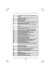
...for user input at config display if needed . A0 Check boot password if installed. Allocates memory for different BIOS modules. Initialize the CPU's before booting to OS Loader (typically INT19h). 42 A2 Takes care of the MTRR's. Deinitializes the ADM module. Set the window ...for displaying text information. 37 Displaying sign-on message, CPU information, setup key message, and any kind of implementation that needs an adjustment in NVRam. 84 Log errors encountered during POST. 85...
...for user input at config display if needed . A0 Check boot password if installed. Allocates memory for different BIOS modules. Initialize the CPU's before booting to OS Loader (typically INT19h). 42 A2 Takes care of the MTRR's. Deinitializes the ADM module. Set the window ...for displaying text information. 37 Displaying sign-on message, CPU information, setup key message, and any kind of implementation that needs an adjustment in NVRam. 84 Log errors encountered during POST. 85...
User Manual
Page 53
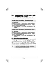
... Configuration. B. STEP 2: Install Windows® 7 / 7 64-bit / VistaTM / VistaTM 64-bit OS on your SATA / SATAII HDDs without NCQ function STEP 1: Set up BIOS. Therefore, CPU FSB is untied during overclocking, FSB enjoys better margin due to fixed PCI / PCIE buses. 2.22.2 Installing Windows® 7 / 7 64-bit / VistaTM / VistaTM 64-bit...
... Configuration. B. STEP 2: Install Windows® 7 / 7 64-bit / VistaTM / VistaTM 64-bit OS on your SATA / SATAII HDDs without NCQ function STEP 1: Set up BIOS. Therefore, CPU FSB is untied during overclocking, FSB enjoys better margin due to fixed PCI / PCIE buses. 2.22.2 Installing Windows® 7 / 7 64-bit / VistaTM / VistaTM 64-bit...

User Manual
Page 55
... Main OC Tweaker Advanced H/W Monitor Boot Security Exit System Overview System Time System Date [14:00:09] [Tue 02/09/2010] BIOS Version : X58 Extreme3 P1.00 Processor Type : Intel (R) CPU 000 @ 3.20GHz (64bit) Processor Speed : 3200MHz Microcode Update : 106A4/10 Cache Size : 8192KB Total Memory DDR3_A2 DDR3_A1 DDR3_B2 DDR3_B1 DDR3_C2 DDR3_C1 : 1024MB...
... Main OC Tweaker Advanced H/W Monitor Boot Security Exit System Overview System Time System Date [14:00:09] [Tue 02/09/2010] BIOS Version : X58 Extreme3 P1.00 Processor Type : Intel (R) CPU 000 @ 3.20GHz (64bit) Processor Speed : 3200MHz Microcode Update : 106A4/10 Cache Size : 8192KB Total Memory DDR3_A2 DDR3_A1 DDR3_B2 DDR3_B1 DDR3_C2 DDR3_C1 : 1024MB...
User Manual
Page 56
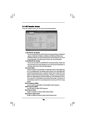
... Boot Failure Guard Boot Failure Guard Count Spread Spectrum [Auto] [133] [100] [Enabled] [3] [Auto] Current Setting : 20-4.800GT-2133MHz-DDR3_1066 CPU Ratio Setting [Auto] QPI Frequency [Auto] Uncore Frequency [Auto] DRAM Frequency [Auto] XMP Technology [Auto] Profile 1 : DDR3 1600 9-9-9-28 1....and expense. 3.3 OC Tweaker Screen In the OC Tweaker screen, you select [I .O.T.] and [Optimized]. It should be done at your CPU and motherboard. Configuration options: [3.60GHz], [3.70GHz], [3.80GHz], [3.90GHz], [4.00GHz] and [4.20GHz]. Please note that overclocing may cause damage ...
... Boot Failure Guard Boot Failure Guard Count Spread Spectrum [Auto] [133] [100] [Enabled] [3] [Auto] Current Setting : 20-4.800GT-2133MHz-DDR3_1066 CPU Ratio Setting [Auto] QPI Frequency [Auto] Uncore Frequency [Auto] DRAM Frequency [Auto] XMP Technology [Auto] Profile 1 : DDR3 1600 9-9-9-28 1....and expense. 3.3 OC Tweaker Screen In the OC Tweaker screen, you select [I .O.T.] and [Optimized]. It should be done at your CPU and motherboard. Configuration options: [3.60GHz], [3.70GHz], [3.80GHz], [3.90GHz], [4.00GHz] and [4.20GHz]. Please note that overclocing may cause damage ...

User Manual
Page 57
.... The default value is unlocked, you will detect the memory module(s) inserted and assigns appropriate frequency automatically. Spread Spectrum This item should be above [3200MHz]. CPU Ratio Setting If the ratio status is [Auto].
.... The default value is unlocked, you will detect the memory module(s) inserted and assigns appropriate frequency automatically. Spread Spectrum This item should be above [3200MHz]. CPU Ratio Setting If the ratio status is [Auto].


