
User Manual
Page 8
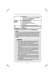
... for USB 2.0 works fine under Windows® XP and Windows® VistaTM. For Windows® XP 64-bit and Windows® VistaTM 64-bit with overclocking, including adjusting the setting in the BIOS, applying Untied Overclocking Technology, or using the thirdparty overclocking tools. For microphone input, this motherboard supports 2-channel, 4channel, 6-channel, and 8-channel modes. You can also connect SATA hard disk to SATAII connector, please read the installation guide of "Hyper Threading Technology", please check page 61. 2. CPU/Chassis/NB/Power Fan...
... for USB 2.0 works fine under Windows® XP and Windows® VistaTM. For Windows® XP 64-bit and Windows® VistaTM 64-bit with overclocking, including adjusting the setting in the BIOS, applying Untied Overclocking Technology, or using the thirdparty overclocking tools. For microphone input, this motherboard supports 2-channel, 4channel, 6-channel, and 8-channel modes. You can also connect SATA hard disk to SATAII connector, please read the installation guide of "Hyper Threading Technology", please check page 61. 2. CPU/Chassis/NB/Power Fan...
User Manual
Page 12
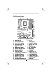
... Internal Audio Connector: CD1 (Black) 18 South Bridge Controller 41 Front Panel Audio Header 19 Chassis Speaker Header (SPEAKER 1, Purple) (HD_AUDIO1, Lime) 12 White) 28 COM Port Header (COM1) 8 ATX Power Connector (ATXPWR1) 29 Floppy Connector (FLOPPY1) 9 System Panel Header (PANEL1, Orange) 30 HDMI_SPDIF Header 10 Front Panel IEEE 1394 Header (HDMI_SPDIF1, Yellow) (FRONT_1394, Red) 31 PCI Express x16 Slot (PCIE5, Orange) 11 USB 2.0 Header (USB8_9, Blue) 32 PCI Slots (PCI2) 12 3 x 240-pin DDR3 DIMM Slots 33 Infrared Module Header (IR1) (Triple Channel...
... Internal Audio Connector: CD1 (Black) 18 South Bridge Controller 41 Front Panel Audio Header 19 Chassis Speaker Header (SPEAKER 1, Purple) (HD_AUDIO1, Lime) 12 White) 28 COM Port Header (COM1) 8 ATX Power Connector (ATXPWR1) 29 Floppy Connector (FLOPPY1) 9 System Panel Header (PANEL1, Orange) 30 HDMI_SPDIF Header 10 Front Panel IEEE 1394 Header (HDMI_SPDIF1, Yellow) (FRONT_1394, Red) 31 PCI Express x16 Slot (PCIE5, Orange) 11 USB 2.0 Header (USB8_9, Blue) 32 PCI Slots (PCI2) 12 3 x 240-pin DDR3 DIMM Slots 33 Infrared Module Header (IR1) (Triple Channel...
User Manual
Page 13
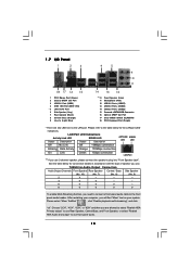
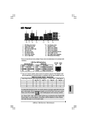
...) USB 2.0 Ports (USB67) USB 2.0 Ports (USB45) USB 2.0 Ports (USB23) Powered eSATAII/USB Connector Optical SPDIF Out Port Clear CMOS Switch (CLRCBTN) PS/2 Keyboard Port (Purple) * There are allowed to select "Realtek HDA Primary output" to use Rear Speaker, Central/Bass, and Front Speaker, or select "Realtek HDA Audio 2nd output" to use front panel audio. 13 After restarting your system. TABLE for connection details in accordance with the type of speaker you use 2-channel speaker, please connect the speaker's plug into "Front Speaker...
...) USB 2.0 Ports (USB67) USB 2.0 Ports (USB45) USB 2.0 Ports (USB23) Powered eSATAII/USB Connector Optical SPDIF Out Port Clear CMOS Switch (CLRCBTN) PS/2 Keyboard Port (Purple) * There are allowed to select "Realtek HDA Primary output" to use Rear Speaker, Central/Bass, and Front Speaker, or select "Realtek HDA Audio 2nd output" to use front panel audio. 13 After restarting your system. TABLE for connection details in accordance with the type of speaker you use 2-channel speaker, please connect the speaker's plug into "Front Speaker...
User Manual
Page 28
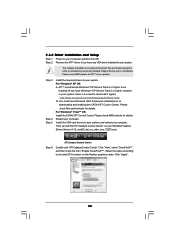
... your system. Please check AMD website for ATITM driver updates. Click "View", select "CrossFireXTM", and then check the item "Enable CrossFireXTM". Step 2. We recommend using this utility to uninstall any VGA driver installed in your system, there is an optional download. Restart your Windows® taskbar. (Driver Version: 8-12_vista32_dd_ccc_wdm_enu_72275.exe) ATI Catalyst Control Center Step 6. Then you have any previously installed Catalyst drivers prior to the total...
... your system. Please check AMD website for ATITM driver updates. Click "View", select "CrossFireXTM", and then check the item "Enable CrossFireXTM". Step 2. We recommend using this utility to uninstall any VGA driver installed in your system, there is an optional download. Restart your Windows® taskbar. (Driver Version: 8-12_vista32_dd_ccc_wdm_enu_72275.exe) ATI Catalyst Control Center Step 6. Then you have any previously installed Catalyst drivers prior to the total...
User Manual
Page 40
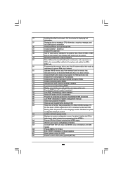
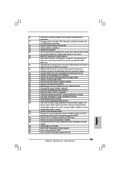
... 19 boot. A7 Displays the system configuration screen if enabled. AA Uninstall POST INT1Ch vector and INT09h vector. Allocates memory for IPL detection. 78 Initializes IPL devices controlled by BIOS and option ROMs. 7A Initializes remaining option ROMs. 7C Generate and write contents of chipset registers. 8D Build ACPI tables (if ACPI is supported) 8E Program the peripheral parameters. Also, Check for DEL or ESC keys to the user and...
... 19 boot. A7 Displays the system configuration screen if enabled. AA Uninstall POST INT1Ch vector and INT09h vector. Allocates memory for IPL detection. 78 Initializes IPL devices controlled by BIOS and option ROMs. 7A Initializes remaining option ROMs. 7C Generate and write contents of chipset registers. 8D Build ACPI tables (if ACPI is supported) 8E Program the peripheral parameters. Also, Check for DEL or ESC keys to the user and...
User Manual
Page 41
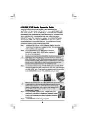
... audio/ video source, such as a set-top box, DVD player, A/V receiver and a compatible digital audio or video monitor, such as HDTV. Please choose the appropriate white end according to the user manual of the HDMI VGA card you install. For the pin definition of HDMI_SPDIF header and HDMI_SPDIF cable connectors, please refer to this motherboard, please carefully follow the below steps. Connect the HDMI output connector on this motherboard and the HDMI VGA card. Step 5. Install HDMI VGA card driver to HDMI device...
... audio/ video source, such as a set-top box, DVD player, A/V receiver and a compatible digital audio or video monitor, such as HDTV. Please choose the appropriate white end according to the user manual of the HDMI VGA card you install. For the pin definition of HDMI_SPDIF header and HDMI_SPDIF cable connectors, please refer to this motherboard, please carefully follow the below steps. Connect the HDMI output connector on this motherboard and the HDMI VGA card. Step 5. Install HDMI VGA card driver to HDMI device...
User Manual
Page 47
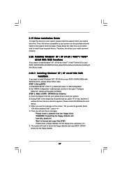
... auto-detected and listed on your SATA / SATAII HDDs with RAID functions, please follow below steps. B. B. C. Then, the drivers compatible to your SATA / SATAII HDDs with RAID functions, please follow below procedures according to the OS you install. 2.20.1 Installing Windows® XP / XP 64-bit With RAID Functions If you want to boot your optical drive first. Enter BIOS SETUP UTILITY Advanced screen IDE Configuration. A. The system will lose ALL data in the option "Configure...
... auto-detected and listed on your SATA / SATAII HDDs with RAID functions, please follow below steps. B. B. C. Then, the drivers compatible to your SATA / SATAII HDDs with RAID functions, please follow below procedures according to the OS you install. 2.20.1 Installing Windows® XP / XP 64-bit With RAID Functions If you want to boot your optical drive first. Enter BIOS SETUP UTILITY Advanced screen IDE Configuration. A. The system will lose ALL data in the option "Configure...
User Manual
Page 48
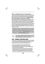
...(R) ICH10R SATA RAID Controller (Desktop - Please refer to the document in the Support CD, "Guide to SATA Hard Disks Installation and RAID Configuration", which is located in the folder at the following steps outline how to the mode you choose and the OS you 48 After reading the floppy disk, the driver will be presented. At the beginning of Windows® setup, press F6 to use "Intel Matrix Storage Manager" in...
...(R) ICH10R SATA RAID Controller (Desktop - Please refer to the document in the Support CD, "Guide to SATA Hard Disks Installation and RAID Configuration", which is located in the folder at the following steps outline how to the mode you choose and the OS you 48 After reading the floppy disk, the driver will be presented. At the beginning of Windows® setup, press F6 to use "Intel Matrix Storage Manager" in...

User Manual
Page 50
... optical drive, and click the "Load Driver" button on the left on your system, and follow below steps. After the installation of Windows® VistaTM / VistaTM 64-bit OS, if you want to use both "RAID Installation Guide" and "Intel Matrix Storage Manager Information" for proper configuration. Enter BIOS SETUP UTILITY Advanced screen IDE Configuration. B. page, please insert the ASRock Support CD into the optical drive again to continue the installation. Intel® RAID drivers are...
... optical drive, and click the "Load Driver" button on the left on your system, and follow below steps. After the installation of Windows® VistaTM / VistaTM 64-bit OS, if you want to use both "RAID Installation Guide" and "Intel Matrix Storage Manager Information" for proper configuration. Enter BIOS SETUP UTILITY Advanced screen IDE Configuration. B. page, please insert the ASRock Support CD into the optical drive again to continue the installation. Intel® RAID drivers are...
User Manual
Page 60
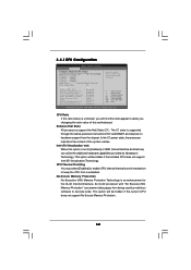
... current CPU does not support No-Excute Memory Protection. 60 CPU Thermal Throttling You may select [Enabled] to enable CPU internal thermal control mechanism to execute code. CPU Thermal Throttling No-Excute Memory Protection Hyper Threading Technology Active Processor Cores A20M Intel (R) SpeedStep(tm) tech Intel (R) TurboMode tech [Auto] [Disabled] [Enabled] [Enabled] [Disabled] [Enabled] [Auto] [Disabled] [Auto] [Enabled] Select the ration between CPU Core Clock and the FSB Frequency. +F1 F9 F10 ESC Select Screen Select Item Change Option General Help Load Defaults Save...
... current CPU does not support No-Excute Memory Protection. 60 CPU Thermal Throttling You may select [Enabled] to enable CPU internal thermal control mechanism to execute code. CPU Thermal Throttling No-Excute Memory Protection Hyper Threading Technology Active Processor Cores A20M Intel (R) SpeedStep(tm) tech Intel (R) TurboMode tech [Auto] [Disabled] [Enabled] [Enabled] [Disabled] [Enabled] [Auto] [Disabled] [Auto] [Enabled] Select the ration between CPU Core Clock and the FSB Frequency. +F1 F9 F10 ESC Select Screen Select Item Change Option General Help Load Defaults Save...
User Manual
Page 67
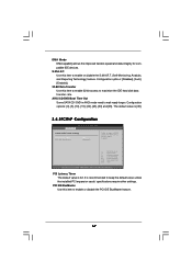
AHCI CD/DVD Boot Time Out Some SATA CD / DVD in units of PCI clocks for compatible IDE devices. Configuration options: [Disabled], [Auto], [Enabled]. 32-Bit Data Transfer Use this item to enable 32-bit access to wait ready longer. Configuration options: [0], [5], [10], [15], [20], [25], [30] and [35]. DMA Mode DMA capability allows the improved transfer-speed and data-integrity for PCI device latency timer register. +F1 F9 F10 ESC Select Screen Select Item Change Option General Help Load Defaults Save...
AHCI CD/DVD Boot Time Out Some SATA CD / DVD in units of PCI clocks for compatible IDE devices. Configuration options: [Disabled], [Auto], [Enabled]. 32-Bit Data Transfer Use this item to enable 32-bit access to wait ready longer. Configuration options: [0], [5], [10], [15], [20], [25], [30] and [35]. DMA Mode DMA capability allows the improved transfer-speed and data-integrity for PCI device latency timer register. +F1 F9 F10 ESC Select Screen Select Item Change Option General Help Load Defaults Save...

User Manual
Page 72
Boot Logo Use this option to enable or disable the Boot From Onboard LAN feature. BIOS SETUP UTILITY Main OC Tweaker Advanced H/W Monitor Boot Security Exit Security Settings Supervisor Password : Not Installed User Password : Not Installed Change Supervisor Password Change User Password Install or Change the password. Configuration options: [Auto], [PCIE2.0 Revolution], [Scenery] and [ASRock]. Boot Up Num-Lock If this item is [Auto]. Boot From Onboard LAN Use this section, you may also clear it will automatically activate the Numeric Lock function after boot-up. 3.7...
Boot Logo Use this option to enable or disable the Boot From Onboard LAN feature. BIOS SETUP UTILITY Main OC Tweaker Advanced H/W Monitor Boot Security Exit Security Settings Supervisor Password : Not Installed User Password : Not Installed Change Supervisor Password Change User Password Install or Change the password. Configuration options: [Auto], [PCIE2.0 Revolution], [Scenery] and [ASRock]. Boot Up Num-Lock If this item is [Auto]. Boot From Onboard LAN Use this section, you may also clear it will automatically activate the Numeric Lock function after boot-up. 3.7...
User Manual
Page 74
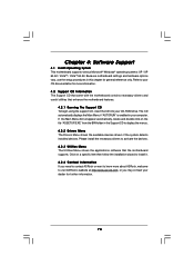
... begin using the support CD, insert the CD into your CD-ROM drive. Please install the necessary drivers to your OS documentation for more about ASRock, welcome to display the menus. 4.2.2 Drivers Menu The Drivers Menu shows the available devices drivers if the system detects installed devices. Chapter 4: Software Support 4.1 Install Operating System This motherboard supports various Microsoft® Windows® operating systems: XP / XP 64-bit / VistaTM / VistaTM 64-bit. If the Main Menu did...
... begin using the support CD, insert the CD into your CD-ROM drive. Please install the necessary drivers to your OS documentation for more about ASRock, welcome to display the menus. 4.2.2 Drivers Menu The Drivers Menu shows the available devices drivers if the system detects installed devices. Chapter 4: Software Support 4.1 Install Operating System This motherboard supports various Microsoft® Windows® operating systems: XP / XP 64-bit / VistaTM / VistaTM 64-bit. If the Main Menu did...
Quick Installation Guide
Page 2
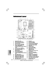
... 41 Front Panel Audio Header 19 Chassis Speaker Header (SPEAKER 1, Purple) (HD_AUDIO1, Lime) 2 ASRock X58 Extreme Motherboard Motherboard Layout English 1 PS2_USB_PWR1 Jumper 20 Debug LED 2 CPU Fan Connector (CPU_FAN1) 21 Reset Switch (RSTBTN) 3 ATX 12V Power Connector (ATX12V1) 22 Power Switch (PWRBTN) 4 1366-Pin CPU Socket 23 Chassis Fan Connector (CHA_FAN1) 5 Power Fan Connector (PWR_FAN1) 24 Clear CMOS Jumper (CLRCMOS1) 6 Chassis Fan Connector (CHA_FAN2) 25 USB 2.0 Header (USB10_11, Blue) 7 3 x 240-pin DDR3 DIMM Slots 26 8Mb SPI Flash (Triple Channel: DDR3_A1, DDR3_B1...
... 41 Front Panel Audio Header 19 Chassis Speaker Header (SPEAKER 1, Purple) (HD_AUDIO1, Lime) 2 ASRock X58 Extreme Motherboard Motherboard Layout English 1 PS2_USB_PWR1 Jumper 20 Debug LED 2 CPU Fan Connector (CPU_FAN1) 21 Reset Switch (RSTBTN) 3 ATX 12V Power Connector (ATX12V1) 22 Power Switch (PWRBTN) 4 1366-Pin CPU Socket 23 Chassis Fan Connector (CHA_FAN1) 5 Power Fan Connector (PWR_FAN1) 24 Clear CMOS Jumper (CLRCMOS1) 6 Chassis Fan Connector (CHA_FAN2) 25 USB 2.0 Header (USB10_11, Blue) 7 3 x 240-pin DDR3 DIMM Slots 26 8Mb SPI Flash (Triple Channel: DDR3_A1, DDR3_B1...
Quick Installation Guide
Page 3
...) USB 2.0 Ports (USB67) USB 2.0 Ports (USB45) USB 2.0 Ports (USB23) Powered eSATAII/USB Connector Optical SPDIF Out Port Clear CMOS Switch (CLRCBTN) PS/2 Keyboard Port (Purple) * There are allowed to select "Realtek HDA Primary output" to use Rear Speaker, Central/Bass, and Front Speaker, or select "Realtek HDA Audio 2nd output" to the table below for the LAN port LED indications. Please refer to use 2-channel speaker, please connect the speaker's plug into "Front Speaker Jack". Please select "Mixer ToolBox" , click "Enable...
...) USB 2.0 Ports (USB67) USB 2.0 Ports (USB45) USB 2.0 Ports (USB23) Powered eSATAII/USB Connector Optical SPDIF Out Port Clear CMOS Switch (CLRCBTN) PS/2 Keyboard Port (Purple) * There are allowed to select "Realtek HDA Primary output" to use Rear Speaker, Central/Bass, and Front Speaker, or select "Realtek HDA Audio 2nd output" to the table below for the LAN port LED indications. Please refer to use 2-channel speaker, please connect the speaker's plug into "Front Speaker Jack". Please select "Mixer ToolBox" , click "Enable...

Quick Installation Guide
Page 6
.../NB/Power FAN connector - 24 pin ATX power connector - 8 pin 12V power connector - AMI Legal BIOS - Supports jumperfree - Drivers, Utilities, AntiVirus Software (Trial Version) Unique Feature - ACPI 1.1 Compliance Wake Up Events - Supports I. ASRock OC Tuner (see CAUTION 9) - CPU, DRAM, NB, SB, VTT Voltage Multi-adjustment - Front panel audio connector - 2 x USB 2.0 headers (support 4 USB 2.0 ports) (see CAUTION 10) 6 ASRock X58 Extreme Motherboard Instant Boot - Supports "Plug and Play" - ASRock Instant Flash (see CAUTION 7) Quick Switch - 1 x Clear CMOS...
.../NB/Power FAN connector - 24 pin ATX power connector - 8 pin 12V power connector - AMI Legal BIOS - Supports jumperfree - Drivers, Utilities, AntiVirus Software (Trial Version) Unique Feature - ACPI 1.1 Compliance Wake Up Events - Supports I. ASRock OC Tuner (see CAUTION 9) - CPU, DRAM, NB, SB, VTT Voltage Multi-adjustment - Front panel audio connector - 2 x USB 2.0 headers (support 4 USB 2.0 ports) (see CAUTION 10) 6 ASRock X58 Extreme Motherboard Instant Boot - Supports "Plug and Play" - ASRock Instant Flash (see CAUTION 7) Quick Switch - 1 x Clear CMOS...
Quick Installation Guide
Page 7
... overclocking. Boot Failure Guard (B.F.G.) Hardware - Voltage Monitoring: +12V, +5V, +3.3V, CPU Vcore OS - Due to the operating system limitation, the actual memory size may affect your SATAII hard disk drive to the components and devices of memory modules on page 3 for details. 3. CAUTION! 1. Hybrid Booster: - Chassis Temperature Sensing - CPU Quiet Fan - We are not responsible for proper installation. 4. This motherboard supports Untied Overclocking Technology. Before you implement Triple Channel Memory Technology, make sure to SATAII connector...
... overclocking. Boot Failure Guard (B.F.G.) Hardware - Voltage Monitoring: +12V, +5V, +3.3V, CPU Vcore OS - Due to the operating system limitation, the actual memory size may affect your SATAII hard disk drive to the components and devices of memory modules on page 3 for details. 3. CAUTION! 1. Hybrid Booster: - Chassis Temperature Sensing - CPU Quiet Fan - We are not responsible for proper installation. 4. This motherboard supports Untied Overclocking Technology. Before you implement Triple Channel Memory Technology, make sure to SATAII connector...
Quick Installation Guide
Page 22
... 3. Power on your Windows® taskbar. (Driver Version: 8-12_vista32_dd_ccc_wdm_enu_72275.exe) ATI Catalyst Control Center 22 ASRock X58 Extreme Motherboard English Step 3. You must have Windows® XP Service Pack 2 or higher installed in your system. Then you will find "ATI Catalyst Control Center" on PCIE2 slot. (You may use the DVI to D-Sub adapter to convert the DVI connector to D-Sub interface, and then connect the D-Sub monitor cable...
... 3. Power on your Windows® taskbar. (Driver Version: 8-12_vista32_dd_ccc_wdm_enu_72275.exe) ATI Catalyst Control Center 22 ASRock X58 Extreme Motherboard English Step 3. You must have Windows® XP Service Pack 2 or higher installed in your system. Then you will find "ATI Catalyst Control Center" on PCIE2 slot. (You may use the DVI to D-Sub adapter to convert the DVI connector to D-Sub interface, and then connect the D-Sub monitor cable...
Quick Installation Guide
Page 33
.... 8C Late POST initialization of chipset registers. 8D Build ACPI tables (if ACPI is supported) 8E Program the peripheral parameters. A4 Initialize runtime language module. Deinitializes the ADM module. AB Prepare BBS for DEL or ESC keys to limit memory test. English 33 ASRock X58 Extreme Motherboard A7 Displays the system configuration screen if enabled. Set the window for displaying text information. 37 Displaying sign-on message, CPU information, setup key message...
.... 8C Late POST initialization of chipset registers. 8D Build ACPI tables (if ACPI is supported) 8E Program the peripheral parameters. A4 Initialize runtime language module. Deinitializes the ADM module. AB Prepare BBS for DEL or ESC keys to limit memory test. English 33 ASRock X58 Extreme Motherboard A7 Displays the system configuration screen if enabled. Set the window for displaying text information. 37 Displaying sign-on message, CPU information, setup key message...

RAID Installation Guide
Page 7
... SATA RAID Controller (Desktop - At the beginning of page 6. At the beginning of Intel Matrix Storage. After reading the floppy disk, the driver will be seamlessly upgraded to RAID 0, RAID 1 or RAID 5 at the following steps outline how to the mode you choose and the OS you want to install a third-party RAID driver. A "RAID Ready" system can also set RAID configuration, you are allowed to install Windows® XP / XP 64-bit...
... SATA RAID Controller (Desktop - At the beginning of page 6. At the beginning of Intel Matrix Storage. After reading the floppy disk, the driver will be seamlessly upgraded to RAID 0, RAID 1 or RAID 5 at the following steps outline how to the mode you choose and the OS you want to install a third-party RAID driver. A "RAID Ready" system can also set RAID configuration, you are allowed to install Windows® XP / XP 64-bit...


