
User Manual
Page 5
.../support/index.asp 1.1 Package Contents ASRock X58 Extreme Motherboard (ATX Form Factor: 12.0-in x 9.6-in, 30.5 cm x 24.4 cm) ASRock X58 Extreme Quick Installation Guide ASRock X58 Extreme Support CD 1 x 80-conductor Ultra ATA 66/100/133 IDE Ribbon Cable 1 x Ribbon Cable for purchasing ASRock X58 Extreme motherboard, a reliable motherboard produced under ASRock's consistently stringent quality control. Chapter 1: Introduction Thank you for a 3.5-in Floppy Drive 4 x Serial ATA...
.../support/index.asp 1.1 Package Contents ASRock X58 Extreme Motherboard (ATX Form Factor: 12.0-in x 9.6-in, 30.5 cm x 24.4 cm) ASRock X58 Extreme Quick Installation Guide ASRock X58 Extreme Support CD 1 x 80-conductor Ultra ATA 66/100/133 IDE Ribbon Cable 1 x Ribbon Cable for purchasing ASRock X58 Extreme motherboard, a reliable motherboard produced under ASRock's consistently stringent quality control. Chapter 1: Introduction Thank you for a 3.5-in Floppy Drive 4 x Serial ATA...
User Manual
Page 12
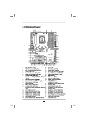
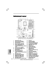
1.6 Motherboard Layout 123 45 6 7 24.4cm (9.6 in) PS2 Mouse PS2 Keyboard Clr...CrossFireX QPI 6.4GT/s 37 36 AUDIO CODEC PCIE2 PCIE3 RoHS 14 1394a VIA VT6330 SATAII_5_6 SATAII_3_4 SATAII_1_2 35 PCI1 X58 Extreme 8Mb BIOS 34 PCIE4 IDE1 15 33 32 31 Super I/O 1 IR1 FLOPPY1 HDMI_SPDIF1 1 PCI2 PCIE5 COM1 1... 8Mb SPI Flash (Triple Channel: DDR3_A1, DDR3_B1, DDR3_C1 27 TPM Header (TPM1) ; White) 28 COM Port Header (COM1) 8 ATX Power Connector (ATXPWR1) 29 Floppy Connector (FLOPPY1) 9 System Panel Header (PANEL1, Orange) 30 HDMI_SPDIF Header 10 Front Panel IEEE 1394 ...
1.6 Motherboard Layout 123 45 6 7 24.4cm (9.6 in) PS2 Mouse PS2 Keyboard Clr...CrossFireX QPI 6.4GT/s 37 36 AUDIO CODEC PCIE2 PCIE3 RoHS 14 1394a VIA VT6330 SATAII_5_6 SATAII_3_4 SATAII_1_2 35 PCI1 X58 Extreme 8Mb BIOS 34 PCIE4 IDE1 15 33 32 31 Super I/O 1 IR1 FLOPPY1 HDMI_SPDIF1 1 PCI2 PCIE5 COM1 1... 8Mb SPI Flash (Triple Channel: DDR3_A1, DDR3_B1, DDR3_C1 27 TPM Header (TPM1) ; White) 28 COM Port Header (COM1) 8 ATX Power Connector (ATXPWR1) 29 Floppy Connector (FLOPPY1) 9 System Panel Header (PANEL1, Orange) 30 HDMI_SPDIF Header 10 Front Panel IEEE 1394 ...
User Manual
Page 14
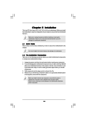
...ICs. 4. Whenever you handle components. 3. Unplug the power cord from the power supply. Doing so may damage the motherboard. 2.2 Pre-installation Precautions Take note of your motherboard directly on a grounded antistatic pad or in the bag that the power is switched off or the power cord is... an ATX form factor (12.0" x 9.6", 30.5 x 24.4 cm) motherboard. Chapter 2: Installation This is detached from the wall socket before touching any component, place it . Make sure to static ...
...ICs. 4. Whenever you handle components. 3. Unplug the power cord from the power supply. Doing so may damage the motherboard. 2.2 Pre-installation Precautions Take note of your motherboard directly on a grounded antistatic pad or in the bag that the power is switched off or the power cord is... an ATX form factor (12.0" x 9.6", 30.5 x 24.4 cm) motherboard. Chapter 2: Installation This is detached from the wall socket before touching any component, place it . Make sure to static ...
User Manual
Page 34
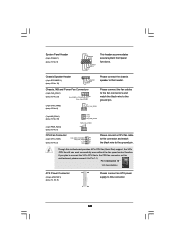
...support, the 3-Pin CPU fan still can work successfully even without the fan speed control function. Though this motherboard, please connect it to the ground pin. Pin 1-3 Connected 3-Pin Fan Installation ATX Power Connector (24-pin ATXPWR1) (see p.12 No. 2) FAN_SPEED_CONTROL 4 CPU_FAN_SPEED 3 +12V 2 GND... 5) GND +12V NB_FAN_SPEED PWR_FAN_SPEED +12V GND CPU Fan Connector (4-pin CPU_FAN1) (see p.12, No. 8) 12 24 1 13 Please connect an ATX power supply to this connector and match the black wire to Pin 1-3. System Panel Header (9-pin PANEL1) (see p.12 No. 19) 1 SPEAKER ...
...support, the 3-Pin CPU fan still can work successfully even without the fan speed control function. Though this motherboard, please connect it to the ground pin. Pin 1-3 Connected 3-Pin Fan Installation ATX Power Connector (24-pin ATXPWR1) (see p.12 No. 2) FAN_SPEED_CONTROL 4 CPU_FAN_SPEED 3 +12V 2 GND... 5) GND +12V NB_FAN_SPEED PWR_FAN_SPEED +12V GND CPU Fan Connector (4-pin CPU_FAN1) (see p.12, No. 8) 12 24 1 13 Please connect an ATX power supply to this connector and match the black wire to Pin 1-3. System Panel Header (9-pin PANEL1) (see p.12 No. 19) 1 SPEAKER ...
User Manual
Page 35
...#1 RRTS#1 GND TTXD1 DDCD#1 Besides one default IEEE 1394 port on this motherboard. Please connect the HDMI_SPDIF connector of HDMI VGA card to this connector. Though this motherboard provides 24-pin ATX power connector, 12 24 it can still work if you adopt a traditional... 4-pin ATX 12V power supply. HDMI_SPDIF Header HDMI_SPDIF header, providing n 1 (3-pin HDMI_SPDIF1) SPDIF audio output to...
...#1 RRTS#1 GND TTXD1 DDCD#1 Besides one default IEEE 1394 port on this motherboard. Please connect the HDMI_SPDIF connector of HDMI VGA card to this connector. Though this motherboard provides 24-pin ATX power connector, 12 24 it can still work if you adopt a traditional... 4-pin ATX 12V power supply. HDMI_SPDIF Header HDMI_SPDIF header, providing n 1 (3-pin HDMI_SPDIF1) SPDIF audio output to...
Quick Installation Guide
Page 2
Motherboard Layout English 1 PS2_USB_PWR1 Jumper 20 Debug LED 2 CPU Fan Connector (CPU_FAN1) 21 Reset Switch (RSTBTN) 3 ATX 12V Power Connector (ATX12V1) 22 Power Switch (PWRBTN) 4 1366-Pin CPU Socket 23 Chassis Fan Connector (CHA_FAN1) 5 Power ...(Black) 18 South Bridge Controller 41 Front Panel Audio Header 19 Chassis Speaker Header (SPEAKER 1, Purple) (HD_AUDIO1, Lime) 2 ASRock X58 Extreme Motherboard White) 28 COM Port Header (COM1) 8 ATX Power Connector (ATXPWR1) 29 Floppy Connector (FLOPPY1) 9 System Panel Header (PANEL1, Orange) 30 HDMI_SPDIF Header 10 Front Panel IEEE...
Motherboard Layout English 1 PS2_USB_PWR1 Jumper 20 Debug LED 2 CPU Fan Connector (CPU_FAN1) 21 Reset Switch (RSTBTN) 3 ATX 12V Power Connector (ATX12V1) 22 Power Switch (PWRBTN) 4 1366-Pin CPU Socket 23 Chassis Fan Connector (CHA_FAN1) 5 Power ...(Black) 18 South Bridge Controller 41 Front Panel Audio Header 19 Chassis Speaker Header (SPEAKER 1, Purple) (HD_AUDIO1, Lime) 2 ASRock X58 Extreme Motherboard White) 28 COM Port Header (COM1) 8 ATX Power Connector (ATXPWR1) 29 Floppy Connector (FLOPPY1) 9 System Panel Header (PANEL1, Orange) 30 HDMI_SPDIF Header 10 Front Panel IEEE...
Quick Installation Guide
Page 4
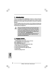
... to quality and endurance. 1. This Quick Installation Guide contains introduction of the motherboard can be available on ASRock website as well. www.asrock.com/support/index.asp 1.1 Package Contents ASRock X58 Extreme Motherboard (ATX Form Factor: 12.0-in x 9.6-in, 30.5 cm x 24.4 cm) ASRock X58 Extreme Quick Installation Guide ASRock X58 Extreme Support CD 1 x 80-conductor Ultra ATA 66/100/133 IDE Ribbon Cable...
... to quality and endurance. 1. This Quick Installation Guide contains introduction of the motherboard can be available on ASRock website as well. www.asrock.com/support/index.asp 1.1 Package Contents ASRock X58 Extreme Motherboard (ATX Form Factor: 12.0-in x 9.6-in, 30.5 cm x 24.4 cm) ASRock X58 Extreme Quick Installation Guide ASRock X58 Extreme Support CD 1 x 80-conductor Ultra ATA 66/100/133 IDE Ribbon Cable...
Quick Installation Guide
Page 5
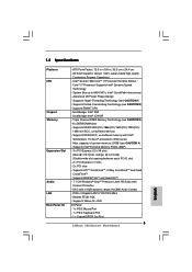
... Mb/s - 1.2 Specifications Platform CPU Chipset Memory Expansion Slot Audio LAN Rear Panel I /O Panel - 1 x PS/2 Mouse Port - 1 x PS/2 Keyboard Port - 1 x Coaxial SPDIF Out Port 5 ASRock X58 Extreme Motherboard English Supports EM64T CPU - ATX Form Factor: 12.0-in x 9.6-in, 30.5 cm x 24.4 cm - Intel® QuickPath Interconnect - Southbridge: Intel® ICH10R - Triple Channel DDR3 Memory Technology (see...
... Mb/s - 1.2 Specifications Platform CPU Chipset Memory Expansion Slot Audio LAN Rear Panel I /O Panel - 1 x PS/2 Mouse Port - 1 x PS/2 Keyboard Port - 1 x Coaxial SPDIF Out Port 5 ASRock X58 Extreme Motherboard English Supports EM64T CPU - ATX Form Factor: 12.0-in x 9.6-in, 30.5 cm x 24.4 cm - Intel® QuickPath Interconnect - Southbridge: Intel® ICH10R - Triple Channel DDR3 Memory Technology (see...

Quick Installation Guide
Page 6
... - 1 x IEEE 1394 header - 1 x TPM header - AMI Legal BIOS - O. T. (Intelligent Overclocking Technology) - CPU/Chassis/NB/Power FAN connector - 24 pin ATX power connector - 8 pin 12V power connector - Supports "Plug and Play" - Supports jumperfree - SMBIOS 2.3.1 Support English - CPU, DRAM, NB, SB, VTT Voltage Multi-... Reset Switch BIOS Feature - 8Mb AMI BIOS - HD Audio Jack: Side Speaker/Rear Speaker/Central/Bass/ Line in header - ASRock OC Tuner (see CAUTION 10) 6 ASRock X58 Extreme Motherboard Supports I. ASRock Instant Flash (see CAUTION 8) -
... - 1 x IEEE 1394 header - 1 x TPM header - AMI Legal BIOS - O. T. (Intelligent Overclocking Technology) - CPU/Chassis/NB/Power FAN connector - 24 pin ATX power connector - 8 pin 12V power connector - Supports "Plug and Play" - Supports jumperfree - SMBIOS 2.3.1 Support English - CPU, DRAM, NB, SB, VTT Voltage Multi-... Reset Switch BIOS Feature - 8Mb AMI BIOS - HD Audio Jack: Side Speaker/Rear Speaker/Central/Bass/ Line in header - ASRock OC Tuner (see CAUTION 10) 6 ASRock X58 Extreme Motherboard Supports I. ASRock Instant Flash (see CAUTION 8) -
Quick Installation Guide
Page 28
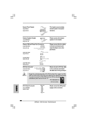
...NB and Power Fan Connectors (4-pin CHA_FAN1) (see p.2 No. 23) (3-pin CHA_FAN2) (see p.2, No. 8) 12 24 1 13 Please connect an ATX power supply to this header. Please connect the fan cables to the fan connectors and match the black wire to the ground pin. (3-pin NB_FAN1... on this motherboard provides 4-Pin CPU fan (Quiet Fan) support, the 3-Pin CPU fan still can work successfully even without the fan speed control function. System Panel Header (9-pin PANEL1) (see p.2 No. 2) Please connect a CPU fan cable 4 3 to this connector. English 28 ASRock X58 Extreme Motherboard
...NB and Power Fan Connectors (4-pin CHA_FAN1) (see p.2 No. 23) (3-pin CHA_FAN2) (see p.2, No. 8) 12 24 1 13 Please connect an ATX power supply to this header. Please connect the fan cables to the fan connectors and match the black wire to the ground pin. (3-pin NB_FAN1... on this motherboard provides 4-Pin CPU fan (Quiet Fan) support, the 3-Pin CPU fan still can work successfully even without the fan speed control function. System Panel Header (9-pin PANEL1) (see p.2 No. 2) Please connect a CPU fan cable 4 3 to this connector. English 28 ASRock X58 Extreme Motherboard
Quick Installation Guide
Page 29
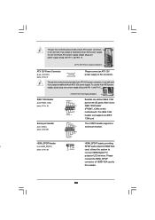
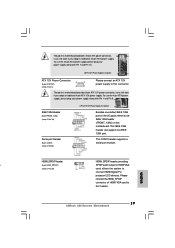
... (9-pin FRONT_1394) (see p.2 No. 10) Serial port Header (9-pin COM1) (see p.2 No.28) 4-Pin ATX 12V Power Supply Installation 4 1 Besides one default IEEE 1394 port on this motherboard. Please connect the HDMI_SPDIF connector of HDMI VGA card to con nect HDMI Digital TV/ projector/LCD devices. This...can support one IEEE 1394 header (FRONT_1394) on the I/O panel, there is one IEEE 1394 port. Though this motherboard provides 24-pin ATX power connector, 12 24 it can still work if you adopt a traditional 4-pin ATX 12V power supply. English 29 ASRock X58 Extreme Motherboard
... (9-pin FRONT_1394) (see p.2 No. 10) Serial port Header (9-pin COM1) (see p.2 No.28) 4-Pin ATX 12V Power Supply Installation 4 1 Besides one default IEEE 1394 port on this motherboard. Please connect the HDMI_SPDIF connector of HDMI VGA card to con nect HDMI Digital TV/ projector/LCD devices. This...can support one IEEE 1394 header (FRONT_1394) on the I/O panel, there is one IEEE 1394 port. Though this motherboard provides 24-pin ATX power connector, 12 24 it can still work if you adopt a traditional 4-pin ATX 12V power supply. English 29 ASRock X58 Extreme Motherboard

