
User Manual
Page 4
... 64-bit Without RAID Functions 51 2.21.2 Installing Windows® VistaTM / VistaTM 64-bit Without RAID Functions 52 2.22 Untied Overclocking Technology 52 3 BIOS SETUP UTILITY 53 3.1 Introduction 53 3.1.1 BIOS Menu Bar 53 3.1.2 Navigation Keys 54 3.2 Main Screen 54 3.3 OC Tweaker Screen 54 3.4 Advanced Screen 59 3.4.1 CPU Configuration 60 3.4.2 Chipset Configuration 63...
... 64-bit Without RAID Functions 51 2.21.2 Installing Windows® VistaTM / VistaTM 64-bit Without RAID Functions 52 2.22 Untied Overclocking Technology 52 3 BIOS SETUP UTILITY 53 3.1 Introduction 53 3.1.1 BIOS Menu Bar 53 3.1.2 Navigation Keys 54 3.2 Main Screen 54 3.3 OC Tweaker Screen 54 3.4 Advanced Screen 59 3.4.1 CPU Configuration 60 3.4.2 Chipset Configuration 63...
User Manual
Page 5
... ASRock X58 Extreme Motherboard (ATX Form Factor: 12.0-in x 9.6-in, 30.5 cm x 24.4 cm) ASRock X58 Extreme Quick Installation Guide ASRock X58 Extreme Support CD 1 x 80-conductor Ultra ATA 66/100/133 IDE Ribbon Cable 1 x Ribbon Cable for purchasing ASRock X58 Extreme motherboard, a reliable motherboard produced under ASRock's consistently stringent quality control. It delivers excellent performance with robust design conforming to ASRock's commitment to BIOS...
... ASRock X58 Extreme Motherboard (ATX Form Factor: 12.0-in x 9.6-in, 30.5 cm x 24.4 cm) ASRock X58 Extreme Quick Installation Guide ASRock X58 Extreme Support CD 1 x 80-conductor Ultra ATA 66/100/133 IDE Ribbon Cable 1 x Ribbon Cable for purchasing ASRock X58 Extreme motherboard, a reliable motherboard produced under ASRock's consistently stringent quality control. It delivers excellent performance with robust design conforming to ASRock's commitment to BIOS...

User Manual
Page 7
... - 1 x IR header - 1 x COM port header - 1 x HDMI_SPDIF header - 1 x IEEE 1394 header - 1 x TPM header - Supports I. ASRock OC Tuner (see CAUTION 9) - Intelligent Energy Saver (see CAUTION 8) - Front panel audio connector - 2 x USB 2.0 headers (support 4 USB 2.0 ports) (see ...CAUTION 10) 7 T. (Intelligent Overclocking Technology) - ASRock Instant Flash (see CAUTION 7) - 1 x Clear CMOS Switch - 1 x Power Switch - 1 x Reset Switch - 8Mb AMI BIOS - AMI Legal BIOS - Connector Quick Switch BIOS Feature Support CD Unique Feature - 7 x Ready-to-Use USB 2.0...
... - 1 x IR header - 1 x COM port header - 1 x HDMI_SPDIF header - 1 x IEEE 1394 header - 1 x TPM header - Supports I. ASRock OC Tuner (see CAUTION 9) - Intelligent Energy Saver (see CAUTION 8) - Front panel audio connector - 2 x USB 2.0 headers (support 4 USB 2.0 ports) (see ...CAUTION 10) 7 T. (Intelligent Overclocking Technology) - ASRock Instant Flash (see CAUTION 7) - 1 x Clear CMOS Switch - 1 x Power Switch - 1 x Reset Switch - 8Mb AMI BIOS - AMI Legal BIOS - Connector Quick Switch BIOS Feature Support CD Unique Feature - 7 x Ready-to-Use USB 2.0...
User Manual
Page 8
... 64-bit / VistaTM / VistaTM 64-bit compliant Certifications - FCC, CE, WHQL * For detailed product information, please visit our website: http://www.asrock.com WARNING Please realize that there is no such limitation. 5. Please read "Untied Overclocking Technology" on page 13 for details. 3. fore you implement ...® VistaTM 64-bit with 64-bit CPU, there is a certain risk involved with overclocking, including adjusting the setting in the BIOS, applying Untied Overclocking Technology, or using the thirdparty overclocking tools. CPU Quiet Fan - It should be less than 4GB for the ...
... 64-bit / VistaTM / VistaTM 64-bit compliant Certifications - FCC, CE, WHQL * For detailed product information, please visit our website: http://www.asrock.com WARNING Please realize that there is no such limitation. 5. Please read "Untied Overclocking Technology" on page 13 for details. 3. fore you implement ...® VistaTM 64-bit with 64-bit CPU, there is a certain risk involved with overclocking, including adjusting the setting in the BIOS, applying Untied Overclocking Technology, or using the thirdparty overclocking tools. CPU Quiet Fan - It should be less than 4GB for the ...
User Manual
Page 9
... 10. While CPU overheat is not recommended to access ASRock Instant Flash. With this utility, you can press key during the POST or press key to BIOS setup menu to perform over-clocking. Just launch this motherboard offers stepless control, it is detected, the.... 9 Before you to update system BIOS without preparing an additional floppy diskette or other than the recommended CPU bus frequencies may cause the instability of ASRock OC Tuner. ASRock website: http://www.asrock.com 9. ASRock Instant Flash is a user-friendly ASRock overclocking tool which allows you resume the...
... 10. While CPU overheat is not recommended to access ASRock Instant Flash. With this utility, you can press key during the POST or press key to BIOS setup menu to perform over-clocking. Just launch this motherboard offers stepless control, it is detected, the.... 9 Before you to update system BIOS without preparing an additional floppy diskette or other than the recommended CPU bus frequencies may cause the instability of ASRock OC Tuner. ASRock website: http://www.asrock.com 9. ASRock Instant Flash is a user-friendly ASRock overclocking tool which allows you resume the...
User Manual
Page 12
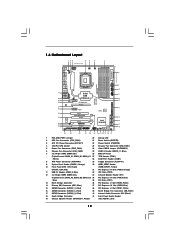
... PCIE1 13 PHY 38 PCI Express 2.0 CrossFireX QPI 6.4GT/s 37 36 AUDIO CODEC PCIE2 PCIE3 RoHS 14 1394a VIA VT6330 SATAII_5_6 SATAII_3_4 SATAII_1_2 35 PCI1 X58 Extreme 8Mb BIOS 34 PCIE4 IDE1 15 33 32 31 Super I/O 1 IR1 FLOPPY1 HDMI_SPDIF1 1 PCI2 PCIE5 COM1 1 1 TPM1 CMOS Battery Intel ICH10R USB10_11 CHA_FAN1 Debug CLRCMOS1 PWRBTN...
... PCIE1 13 PHY 38 PCI Express 2.0 CrossFireX QPI 6.4GT/s 37 36 AUDIO CODEC PCIE2 PCIE3 RoHS 14 1394a VIA VT6330 SATAII_5_6 SATAII_3_4 SATAII_1_2 35 PCI1 X58 Extreme 8Mb BIOS 34 PCIE4 IDE1 15 33 32 31 Super I/O 1 IR1 FLOPPY1 HDMI_SPDIF1 1 PCI2 PCIE5 COM1 1 1 TPM1 CMOS Battery Intel ICH10R USB10_11 CHA_FAN1 Debug CLRCMOS1 PWRBTN...
User Manual
Page 30
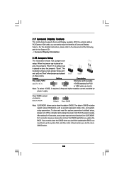
... Display Information 2.10 Jumpers Setup The illustration shows how jumpers are "Short" when jumper cap is placed on PCI Express VGA cards, you update the BIOS. With the external add-on these 2 pins. If no jumper cap is placed on pins, the jumper is "Short". Note: To select +5VSB, it ... Display feature. However, please do the clearCMOS action. 30 For the detailed instruction, please refer to clear the CMOS when you just finish updating the BIOS, you to enable +5VSB (standby) for PS/2 +5V +5VSB or USB wake up the system first, and then shut it requires 2 Amp and higher ...
... Display Information 2.10 Jumpers Setup The illustration shows how jumpers are "Short" when jumper cap is placed on PCI Express VGA cards, you update the BIOS. With the external add-on these 2 pins. If no jumper cap is placed on pins, the jumper is "Short". Note: To select +5VSB, it ... Display feature. However, please do the clearCMOS action. 30 For the detailed instruction, please refer to clear the CMOS when you just finish updating the BIOS, you to enable +5VSB (standby) for PS/2 +5V +5VSB or USB wake up the system first, and then shut it requires 2 Amp and higher ...
User Manual
Page 33
C. D. Enter Advanced Settings, and then select Chipset Configuration. Enter BIOS Setup Utility. Click the icon on the chassis must support HDA to the front panel audio header as the default record device. 33 To activate ...
C. D. Enter Advanced Settings, and then select Chipset Configuration. Enter BIOS Setup Utility. Click the icon on the chassis must support HDA to the front panel audio header as the default record device. 33 To activate ...
User Manual
Page 38
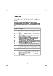
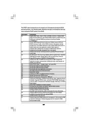
... that may occur during the bootblock initialization portion of RAM. Go to execute serial flash. Verify that flat mode is used to determine if BIOS recovery is enabled. Re-enable CACHE. Test base 512KB memory. Adjust policies and cache first 8MB. Set stack. Both key sequence and OEM... specific method is checked to provide code information, which makes troubleshooting even easier. Main BIOS checksum is given to lower system memory and control is tested. Determine whether to flat mode with 4GB limit and GA20 enabled. Restore CPUID ...
... that may occur during the bootblock initialization portion of RAM. Go to execute serial flash. Verify that flat mode is used to determine if BIOS recovery is enabled. Re-enable CACHE. Test base 512KB memory. Adjust policies and cache first 8MB. Set stack. Both key sequence and OEM... specific method is checked to provide code information, which makes troubleshooting even easier. Main BIOS checksum is given to lower system memory and control is tested. Determine whether to flat mode with 4GB limit and GA20 enabled. Restore CPUID ...
User Manual
Page 39
...boot strap proccessor Early CPU Init Exit Initializes the 8042 compatible Key Board Controller. Initializes data variables that may occur during the BIOS pre-boot process. Initializes the CPU. Detects the presence of checkpoints that are the largest set up boot strap proccessor for ... for more information. Init Local APIC Set up boot strap proccessor Information Set up application proccessors Re-enable cache for initialization. Initialize BIOS, POST, Runtime data area. Detects the presence of chipset registers. Give control to determine if battery power is OK and CMOS ...
...boot strap proccessor Early CPU Init Exit Initializes the 8042 compatible Key Board Controller. Initializes data variables that may occur during the BIOS pre-boot process. Initializes the CPU. Detects the presence of checkpoints that are the largest set up boot strap proccessor for ... for more information. Init Local APIC Set up boot strap proccessor Information Set up application proccessors Re-enable cache for initialization. Initialize BIOS, POST, Runtime data area. Detects the presence of chipset registers. Give control to determine if battery power is OK and CMOS ...
User Manual
Page 40
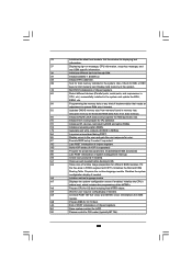
... INT1Ch vector and INT09h vector. Enable/Disable NMI as selected 90 Late POST initialization of runtime image preparation for error. 87 Execute BIOS setup if needed . 33 Initializes the silent boot module. Disables the system configuration display if needed / requested. 8C Late POST ... of POST initialization of ESCD in F000h segment with 0FFh. Also, Check for IPL detection. 78 Initializes IPL devices controlled by BIOS and option ROMs. 7A Initializes remaining option ROMs. 7C Generate and write contents of chipset registers. A0 Check boot password if ...
... INT1Ch vector and INT09h vector. Enable/Disable NMI as selected 90 Late POST initialization of runtime image preparation for error. 87 Execute BIOS setup if needed . 33 Initializes the silent boot module. Disables the system configuration display if needed / requested. 8C Late POST ... of POST initialization of ESCD in F000h segment with 0FFh. Also, Check for IPL detection. 78 Initializes IPL devices controlled by BIOS and option ROMs. 7A Initializes remaining option ROMs. 7C Generate and write contents of chipset registers. A0 Check boot password if ...
User Manual
Page 47
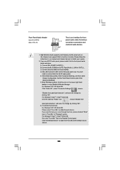
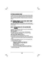
... floppy diskette. 47 STEP 1: Set up , press key, and then a window for boot devices selection appears. During POST at the beginning of system boot-up BIOS. B. Enter BIOS SETUP UTILITY Advanced screen IDE Configuration. Therefore, the drivers you install can be auto-detected and listed on the support CD driver page. A.
... floppy diskette. 47 STEP 1: Set up , press key, and then a window for boot devices selection appears. During POST at the beginning of system boot-up BIOS. B. Enter BIOS SETUP UTILITY Advanced screen IDE Configuration. Therefore, the drivers you install can be auto-detected and listed on the support CD driver page. A.
User Manual
Page 48
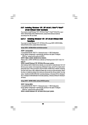
... Controller (Desktop - Assemble the system and attach a single SATA / SATAII hard drive. 2. At the beginning of Windows® setup, press F6 to set up system BIOS as step 2 of Windows® XP / Windows® XP-64bit OS, if you want to use both "RAID Installation Guide" and "Intel Matrix Storage Manager...
... Controller (Desktop - Assemble the system and attach a single SATA / SATAII hard drive. 2. At the beginning of Windows® setup, press F6 to set up system BIOS as step 2 of Windows® XP / Windows® XP-64bit OS, if you want to use both "RAID Installation Guide" and "Intel Matrix Storage Manager...

User Manual
Page 50
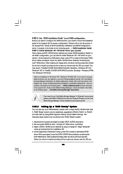
... and the document in the support CD, "Guide to boot your system, and follow below steps. STEP 1: Set up BIOS. Enter BIOS SETUP UTILITY Advanced screen IDE Configuration. page, please insert the ASRock Support CD into the optical drive to Intel Matrix Storage Manager", which is located in the Support CD for RAID...
... and the document in the support CD, "Guide to boot your system, and follow below steps. STEP 1: Set up BIOS. Enter BIOS SETUP UTILITY Advanced screen IDE Configuration. page, please insert the ASRock Support CD into the optical drive to Intel Matrix Storage Manager", which is located in the Support CD for RAID...
User Manual
Page 51
... XP / XP 64-bit OS on your system. 51 When prompted, insert the SATA / SATAII driver diskette containing the Intel® AHCI driver. Enter BIOS SETUP UTILITY Advanced screen IDE Configuration. Set "SATAII Configuration" to [Enhanced], and then in the option "Configure SATAII as ", please set the option to... to install Windows® XP / XP 64-bit OS on your system. Using SATA / SATAII HDDs with NCQ function STEP 1: Set Up BIOS. Using SATA / SATAII HDDs without NCQ function STEP 1: Set up BIOS. Please make a SATA / SATAII driver diskette by following section 2.20.1 step 2 on page 47.
... XP / XP 64-bit OS on your system. 51 When prompted, insert the SATA / SATAII driver diskette containing the Intel® AHCI driver. Enter BIOS SETUP UTILITY Advanced screen IDE Configuration. Set "SATAII Configuration" to [Enhanced], and then in the option "Configure SATAII as ", please set the option to... to install Windows® XP / XP 64-bit OS on your system. Using SATA / SATAII HDDs with NCQ function STEP 1: Set Up BIOS. Using SATA / SATAII HDDs without NCQ function STEP 1: Set up BIOS. Please make a SATA / SATAII driver diskette by following section 2.20.1 step 2 on page 47.

User Manual
Page 52
..., and click the "Load Driver" button on the left on your system. Enter BIOS SETUP UTILITY Advanced screen IDE Configuration. Enter BIOS SETUP UTILITY Advanced screen IDE Configuration. page, please insert the ASRock Support CD into the optical drive to boot your SATA / SATAII HDDs without NCQ ...function STEP 1: Set up BIOS. Set "SATAII Configuration" to [Enhanced], and then in the fixed mode so that , please insert Windows® ...
..., and click the "Load Driver" button on the left on your system. Enter BIOS SETUP UTILITY Advanced screen IDE Configuration. Enter BIOS SETUP UTILITY Advanced screen IDE Configuration. page, please insert the ASRock Support CD into the optical drive to boot your SATA / SATAII HDDs without NCQ ...function STEP 1: Set up BIOS. Set "SATAII Configuration" to [Enhanced], and then in the fixed mode so that , please insert Windows® ...
User Manual
Page 53
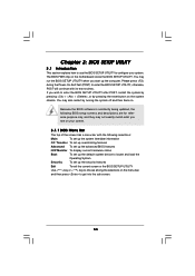
... match what you see on your system. You may also restart by pressing the reset button on the motherboard stores the BIOS SETUP UTILITY. Because the BIOS software is constantly being updated, the following selections: Main To set up the system time/date information OC Tweaker To set... up overclocking features Advanced To set up the advanced BIOS features H/W Monitor To display current hardware status Boot To set up the default system device to locate and load the Operating System Security...
... match what you see on your system. You may also restart by pressing the reset button on the motherboard stores the BIOS SETUP UTILITY. Because the BIOS software is constantly being updated, the following selections: Main To set up the system time/date information OC Tweaker To set... up overclocking features Advanced To set up the advanced BIOS features H/W Monitor To display current hardware status Boot To set up the default system device to locate and load the Operating System Security...
User Manual
Page 54
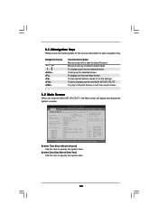
... UTILITY To jump to the Exit Screen or exit the current screen 3.2 Main Screen When you enter the BIOS SETUP UTILITY, the Main screen will appear and display the system overview. Use [+] or [-] to specify the system date. 54 Navigation Key(s) / / + / ... UTILITY Main OC Tweaker Advanced H/W Monitor Boot Security Exit System Overview System Time System Date [14:00:09] [Mon 07/20/2009] BIOS Version : X58 Extreme P1.00 Processor Type : Intel (R) CPU 000 @ 3.20GHz (64bit) Processor Speed : 3200MHz Microcode Update : 106A4/10 Cache Size : 8192KB Total Memory DDR3_A2 DDR3_A1...
... UTILITY To jump to the Exit Screen or exit the current screen 3.2 Main Screen When you enter the BIOS SETUP UTILITY, the Main screen will appear and display the system overview. Use [+] or [-] to specify the system date. 54 Navigation Key(s) / / + / ... UTILITY Main OC Tweaker Advanced H/W Monitor Boot Security Exit System Overview System Time System Date [14:00:09] [Mon 07/20/2009] BIOS Version : X58 Extreme P1.00 Processor Type : Intel (R) CPU 000 @ 3.20GHz (64bit) Processor Speed : 3200MHz Microcode Update : 106A4/10 Cache Size : 8192KB Total Memory DDR3_A2 DDR3_A1...
User Manual
Page 55
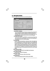
... loaded. PCIE Frequency (MHz) Use this option to load DDR3 EZ overclocking setting. Boot Failure Guard Enable or disable the feature of Untied Overclocking Technology. BIOS SETUP UTILITY Main OC Tweaker Advanced H/W Monitor Boot Security Exit OC Tweaker Settings Load CPU EZ OC Setting Load DDR3 EZ OC Setting [Press Enter...
... loaded. PCIE Frequency (MHz) Use this option to load DDR3 EZ overclocking setting. Boot Failure Guard Enable or disable the feature of Untied Overclocking Technology. BIOS SETUP UTILITY Main OC Tweaker Advanced H/W Monitor Boot Security Exit OC Tweaker Settings Load CPU EZ OC Setting Load DDR3 EZ OC Setting [Press Enter...

User Manual
Page 56
... may select [Auto], [400MHz (DDR3 800)], [533MHz (DDR3 1066)], [666MHz (DDR3 1333)], [800MHz (DDR3 1600)], [933MHz (DDR3 1866)] or [1066MHz (DDR3 2133)]. DRAM Timing Control BIOS SETUP UTILITY Advanced DRAM Timing Control Current Setting : 8-8-8-20-48-8-4-6-5-21 DRAM tCL [Auto] DRAM tRCD [Auto] DRAM tRP [Auto] DRAM tRAS [Auto] DRAM tRFC...
... may select [Auto], [400MHz (DDR3 800)], [533MHz (DDR3 1066)], [666MHz (DDR3 1333)], [800MHz (DDR3 1600)], [933MHz (DDR3 1866)] or [1066MHz (DDR3 2133)]. DRAM Timing Control BIOS SETUP UTILITY Advanced DRAM Timing Control Current Setting : 8-8-8-20-48-8-4-6-5-21 DRAM tCL [Auto] DRAM tRCD [Auto] DRAM tRP [Auto] DRAM tRAS [Auto] DRAM tRFC...


