User Manual
Page 1
All rights reserved. 1 M3A790GXH/128M User Manual Version 1.1 Published July 2009 Copyright©2009 ASRock INC.
All rights reserved. 1 M3A790GXH/128M User Manual Version 1.1 Published July 2009 Copyright©2009 ASRock INC.
User Manual
Page 2
...liable for any interference received, including interference that may apply, see www.dtsc.ca.gov/hazardouswaste/perchlorate" ASRock Website: http://www.asrock.com 2 Copyright Notice: No part of this manual may be reproduced, transcribed, transmitted, or translated in any language, in any form or by any...purpose, without notice, and should not be constructed as a commitment by the California Legislature. With respect to the contents of this manual, ASRock does not provide warranty of any kind, either expressed or implied, including but not limited to infringe. CALIFORNIA, USA ONLY The ...
...liable for any interference received, including interference that may apply, see www.dtsc.ca.gov/hazardouswaste/perchlorate" ASRock Website: http://www.asrock.com 2 Copyright Notice: No part of this manual may be reproduced, transcribed, transmitted, or translated in any language, in any form or by any...purpose, without notice, and should not be constructed as a commitment by the California Legislature. With respect to the contents of this manual, ASRock does not provide warranty of any kind, either expressed or implied, including but not limited to infringe. CALIFORNIA, USA ONLY The ...
User Manual
Page 5
..., 30.5 cm x 22.4 cm) 1 x ASRock M3A790GXH/128M Quick Installation Guide 2 x ASRock M3A790GXH/128M Support CD 1 x Ultra ATA 66/100/133 IDE Ribbon Cable (80-conductor) 1 x Ribbon Cable for purchasing ASRock M3A790GXH/128M motherboard, a reliable motherboard produced under ASRock's consistently stringent quality control. Because the motherboard specifications and the BIOS software might be subject to this manual occur, the updated version will...
..., 30.5 cm x 22.4 cm) 1 x ASRock M3A790GXH/128M Quick Installation Guide 2 x ASRock M3A790GXH/128M Support CD 1 x Ultra ATA 66/100/133 IDE Ribbon Cable (80-conductor) 1 x Ribbon Cable for purchasing ASRock M3A790GXH/128M motherboard, a reliable motherboard produced under ASRock's consistently stringent quality control. Because the motherboard specifications and the BIOS software might be subject to this manual occur, the updated version will...
User Manual
Page 17
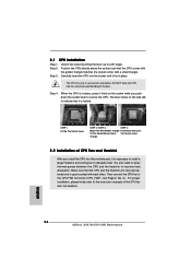
... matches the socket corner with each other. Then connect the CPU fan to improve heat dissipation. For proper installation, please kindly refer to the instruction manuals of CPU Fan and Heatsink After you push down the socket lever to a 90o angle. You also need to spray thermal grease between the CPU...
... matches the socket corner with each other. Then connect the CPU fan to improve heat dissipation. For proper installation, please kindly refer to the instruction manuals of CPU Fan and Heatsink After you push down the socket lever to a 90o angle. You also need to spray thermal grease between the CPU...

User Manual
Page 25
...a 16-pipe card, both cards will operate as 12-pipe cards while in the future, please refer to ATITM graphics card manuals for ATITM CrossFireXTM and 3-Way CrossFireXTM driver updates. 1. If you pair a 12-pipe CrossFireTM Edition card with Windows® VistaTM OS. Step... 1. ASRock SLI/XFire Switch Card is one ASRock SLI/XFire Switch Card factory-mounted on this motherboard. Please check AMD website for detailed installation guide. For other CrossFireXTM cards that...
...a 16-pipe card, both cards will operate as 12-pipe cards while in the future, please refer to ATITM graphics card manuals for ATITM CrossFireXTM and 3-Way CrossFireXTM driver updates. 1. If you pair a 12-pipe CrossFireTM Edition card with Windows® VistaTM OS. Step... 1. ASRock SLI/XFire Switch Card is one ASRock SLI/XFire Switch Card factory-mounted on this motherboard. Please check AMD website for detailed installation guide. For other CrossFireXTM cards that...
User Manual
Page 37
...", and save the change by clicking "OK". Click "Set Default Device" to install your voice through front mic, please deselect "Mute" icon in our manual and chassis manual to make the Front Mic as below: A. High Definition Audio supports Jack Sensing, but the panel wire on the lower right hand taskbar to...
...", and save the change by clicking "OK". Click "Set Default Device" to install your voice through front mic, please deselect "Mute" icon in our manual and chassis manual to make the Front Mic as below: A. High Definition Audio supports Jack Sensing, but the panel wire on the lower right hand taskbar to...
User Manual
Page 41
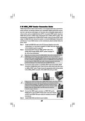
...to the HDMI_SPDIF connector of HDMI VGA card vendor. Connect the white end (B or C) of HDMI_SPDIF cable to the user manual of HDMI VGA card. (There are two white ends (2-pin and 3-pin) on this motherboard, please carefully follow the ... card according to your system. 41 Please refer to the user manual of HDTV and HDMI VGA card vendor for connector usage in advance. Please refer to the VGA card... user manual for detailed connection procedures. Connect the black end (A) of HDMI VGA card, please refer...
...to the HDMI_SPDIF connector of HDMI VGA card vendor. Connect the white end (B or C) of HDMI_SPDIF cable to the user manual of HDMI VGA card. (There are two white ends (2-pin and 3-pin) on this motherboard, please carefully follow the ... card according to your system. 41 Please refer to the user manual of HDTV and HDMI VGA card vendor for connector usage in advance. Please refer to the VGA card... user manual for detailed connection procedures. Connect the black end (A) of HDMI VGA card, please refer...
User Manual
Page 47
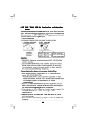
..., which cannot support Hot Plug function, will cause the HDD damage and data loss. Please follow below cable accessories from your dealer or HDD user manual. Make sure to reduce the risk of our motherboard is designed only for SATA / SATAII HDD in the product spec on our support website: www...
..., which cannot support Hot Plug function, will cause the HDD damage and data loss. Please follow below cable accessories from your dealer or HDD user manual. Make sure to reduce the risk of our motherboard is designed only for SATA / SATAII HDD in the product spec on our support website: www...

User Manual
Page 60
...] Memory Clock Flexibility Option [Auto] [Disabled] If AUTO, multiplier and voltage will be left at the rated frequency/voltage. The default value is [Auto]. If Manual, multiplier and voltage will be set the configurations for CPU WARNING : Setting wrong values in Setup. +F1 F9 F10 ESC Select Screen Select Item Change...
...] Memory Clock Flexibility Option [Auto] [Disabled] If AUTO, multiplier and voltage will be left at the rated frequency/voltage. The default value is [Auto]. If Manual, multiplier and voltage will be set the configurations for CPU WARNING : Setting wrong values in Setup. +F1 F9 F10 ESC Select Screen Select Item Change...
User Manual
Page 61
... chipset. Please note that enabling this item to [Enabled]. Enhance Halt State All processors support the Halt State (C1). The C1 state is set to [Manual], you install Windows® VistaTM and want to enable this function, please set this function may adjust the value of Processor Frequency and Processor Voltage...
... chipset. Please note that enabling this item to [Enabled]. Enhance Halt State All processors support the Halt State (C1). The C1 state is set to [Manual], you install Windows® VistaTM and want to enable this function, please set this function may adjust the value of Processor Frequency and Processor Voltage...
User Manual
Page 62
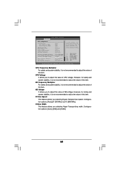
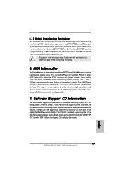
...[Disabled] [BSP Only] Processor Maximum Frequency x31.5 6300 MHZ North Bridge Maximum Frequency x31.0 6200 MHz Processor Maximum Voltage 1.5500 V Multiplier/Voltage Change [Manual] CPU Frequency Multiplier [x0.5 100 MHz] CPU Voltage [0.6000 V] NB Frequency Multiplier [x5.0 1000 MHz] If AUTO, multiplier and voltage will be ...to adjust the value of CPU voltage. Configuration options: [Auto],[x1 200 MHz] to adjust the value of NB voltage. If Manual, multiplier and voltage will be set based on User Selection in Setup. +F1 F9 F10 ESC Select Screen Select Item Change Option...
...[Disabled] [BSP Only] Processor Maximum Frequency x31.5 6300 MHZ North Bridge Maximum Frequency x31.0 6200 MHz Processor Maximum Voltage 1.5500 V Multiplier/Voltage Change [Manual] CPU Frequency Multiplier [x0.5 100 MHz] CPU Voltage [0.6000 V] NB Frequency Multiplier [x5.0 1000 MHz] If AUTO, multiplier and voltage will be ...to adjust the value of CPU voltage. Configuration options: [Auto],[x1 200 MHz] to adjust the value of NB voltage. If Manual, multiplier and voltage will be set based on User Selection in Setup. +F1 F9 F10 ESC Select Screen Select Item Change Option...
Quick Installation Guide
Page 4
... stringent quality control. Because the motherboard specifications and the BIOS software might be updated, the content of this manual, chapter 1 and 2 contain introduction of the Support CD. www.asrock.com/support/index.asp 1.1 Package Contents 1 x ASRock M3A790GXH/128M Motherboard (ATX Form Factor: 12.0-in x 8.8-in Floppy Drive 4 x Serial ATA (SATA) Data Cables (Optional) 1 x Serial ATA...
... stringent quality control. Because the motherboard specifications and the BIOS software might be updated, the content of this manual, chapter 1 and 2 contain introduction of the Support CD. www.asrock.com/support/index.asp 1.1 Package Contents 1 x ASRock M3A790GXH/128M Motherboard (ATX Form Factor: 12.0-in x 8.8-in Floppy Drive 4 x Serial ATA (SATA) Data Cables (Optional) 1 x Serial ATA...
Quick Installation Guide
Page 8
... installation procedures. 12. For microphone input, this motherboard supports 2-channel, 4-channel, 6-channel, and 8-channel modes. You can reduce the number of "User Manual" in advance. 6. ASRock website: http://www.asrock.com 8 ASRock M3A790GXH/128M Motherboard English It is a multi-channel digital surround sound format. Please read the "SATAII Hard Disk Setup Guide" on page 37 for...
... installation procedures. 12. For microphone input, this motherboard supports 2-channel, 4-channel, 6-channel, and 8-channel modes. You can reduce the number of "User Manual" in advance. 6. ASRock website: http://www.asrock.com 8 ASRock M3A790GXH/128M Motherboard English It is a multi-channel digital surround sound format. Please read the "SATAII Hard Disk Setup Guide" on page 37 for...
Quick Installation Guide
Page 14
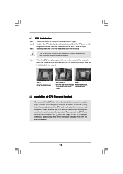
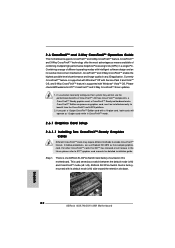
... to the instruction manuals of the CPU fan and the heatsink. Step 2. The lever clicks on the socket while you install the CPU into the socket to dissipate heat. Make sure that the CPU corner with the golden triangle matches the socket corner with each other. English 14 ASRock M3A790GXH/128M Motherboard Step 3. For...
... to the instruction manuals of the CPU fan and the heatsink. Step 2. The lever clicks on the socket while you install the CPU into the socket to dissipate heat. Make sure that the CPU corner with the golden triangle matches the socket corner with each other. English 14 ASRock M3A790GXH/128M Motherboard Step 3. For...
Quick Installation Guide
Page 22
... Installing Two CrossFireXTM-Ready Graphics Cards Different CrossFireXTM cards may require different methods to enable CrossFireXTM feature. English 22 ASRock M3A790GXH/128M Motherboard 2.6 CrossFireXTM and 3-Way CrossFireXTM Operation Guide This motherboard supports CrossFireXTM and 3-Way CrossFireXTM feature. Combining a range... co-processor graphics card, must be installed correctly to ATITM graphics card manuals for ATITM CrossFireXTM and 3-Way CrossFireXTM driver updates. 1. ASRock SLI/XFire Switch Card is one ASRock SLI/XFire Switch Card factory-mounted on this motherboard.
... Installing Two CrossFireXTM-Ready Graphics Cards Different CrossFireXTM cards may require different methods to enable CrossFireXTM feature. English 22 ASRock M3A790GXH/128M Motherboard 2.6 CrossFireXTM and 3-Way CrossFireXTM Operation Guide This motherboard supports CrossFireXTM and 3-Way CrossFireXTM feature. Combining a range... co-processor graphics card, must be installed correctly to ATITM graphics card manuals for ATITM CrossFireXTM and 3-Way CrossFireXTM driver updates. 1. ASRock SLI/XFire Switch Card is one ASRock SLI/XFire Switch Card factory-mounted on this motherboard.
Quick Installation Guide
Page 34
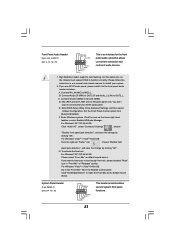
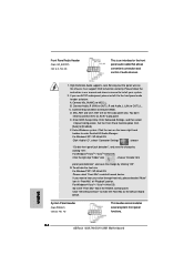
... 64-bit OS: Click the right-top "Folder" icon , choose "Disable front panel jack detection", and save the change by clicking "OK". English 34 ASRock M3A790GXH/128M Motherboard Connect Mic_IN (MIC) to OUT2_L. G. Set the Front Panel Control option from [Auto] to Ground (GND). F. For Windows® XP / XP... Audio Header (9-pin HD_AUDIO1) (see p.2 No. 16) This header accommodates several system front panel functions. Please follow the instruction in our manual and chassis manual to the front panel audio header as the default record device. D. To activate the front mic.
... 64-bit OS: Click the right-top "Folder" icon , choose "Disable front panel jack detection", and save the change by clicking "OK". English 34 ASRock M3A790GXH/128M Motherboard Connect Mic_IN (MIC) to OUT2_L. G. Set the Front Panel Control option from [Auto] to Ground (GND). F. For Windows® XP / XP... Audio Header (9-pin HD_AUDIO1) (see p.2 No. 16) This header accommodates several system front panel functions. Please follow the instruction in our manual and chassis manual to the front panel audio header as the default record device. D. To activate the front mic.
Quick Installation Guide
Page 43
It is enabled in the Support CD to display the menus. 43 ASRock M3A790GXH/128M Motherboard English For the detailed information about BIOS Setup, please refer to [CPU, PCIE, Async.]. It will enhance motherboard features. Before you enable Untied Overclocking ... you start up the computer, please press during overclocking, FSB enjoys better margin due to enter BIOS Setup utility; EXE" from [Auto] to the User Manual (PDF file) contained in the fixed mode so that will display the Main Menu automatically if "AUTORUN" is a menu-driven program, which means during the...
It is enabled in the Support CD to display the menus. 43 ASRock M3A790GXH/128M Motherboard English For the detailed information about BIOS Setup, please refer to [CPU, PCIE, Async.]. It will enhance motherboard features. Before you enable Untied Overclocking ... you start up the computer, please press during overclocking, FSB enjoys better margin due to enter BIOS Setup utility; EXE" from [Auto] to the User Manual (PDF file) contained in the fixed mode so that will display the Main Menu automatically if "AUTORUN" is a menu-driven program, which means during the...
RAID Installation Guide
Page 2
... Striping) RAID 0 is saved to a second drive. When one drive to the next drive automatically. For optimal performance, please install identical drives of the "User Manual" in parallel, interleaved stacks. Although RAID 0 function can start to use the onboard FastBuild BIOS utility to configure RAID. 1.1 Introduction to the surviving drive as...
... Striping) RAID 0 is saved to a second drive. When one drive to the next drive automatically. For optimal performance, please install identical drives of the "User Manual" in parallel, interleaved stacks. Although RAID 0 function can start to use the onboard FastBuild BIOS utility to configure RAID. 1.1 Introduction to the surviving drive as...
RAID Installation Guide
Page 8
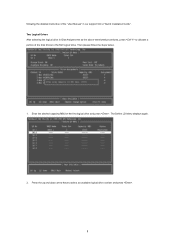
Enter the desired capacity (MB) for the first logical drive and press . Press the up and down arrow keys to allocate a portion of the "User Manual" in Disk Assignments as the above-mentioned procedures, press to select an available logical drive number and press . 8 Then please follow the steps below. 1. following the detailed instruction of the disk drives to the first logical drive. The Define LD Menu displays again. 2. Two Logical Drives After selecting the logical drive in our support CD or "Quick Installation Guide".
Enter the desired capacity (MB) for the first logical drive and press . Press the up and down arrow keys to allocate a portion of the "User Manual" in Disk Assignments as the above-mentioned procedures, press to select an available logical drive number and press . 8 Then please follow the steps below. 1. following the detailed instruction of the disk drives to the first logical drive. The Define LD Menu displays again. 2. Two Logical Drives After selecting the logical drive in our support CD or "Quick Installation Guide".
RAID Installation Guide
Page 9
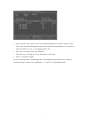
Note that the disk drives in Channels 1 and 2 reflect smaller capacities because a portion of the "User Manual" in Channels 3 and 4 are not assigned to save your computer by following the detailed instruction of their capacity belongs to restart the computer. Press to ...
Note that the disk drives in Channels 1 and 2 reflect smaller capacities because a portion of the "User Manual" in Channels 3 and 4 are not assigned to save your computer by following the detailed instruction of their capacity belongs to restart the computer. Press to ...
