User Manual
Page 4
... 56 3.1 Introduction 56 3.1.1 BIOS Menu Bar 56 3.1.2 Navigation Keys 57 3.2 Main Screen 57 3.3 Smart Screen 58 3.4 Advanced Screen 60 3.4.1 CPU Configuration 61 3.4.2 Memory Configuration 63 3.4.3 Chipset Configuration 67 3.4.4 ACPI ...
... 56 3.1 Introduction 56 3.1.1 BIOS Menu Bar 56 3.1.2 Navigation Keys 57 3.2 Main Screen 57 3.3 Smart Screen 58 3.4 Advanced Screen 60 3.4.1 CPU Configuration 61 3.4.2 Memory Configuration 63 3.4.3 Chipset Configuration 67 3.4.4 ACPI ...
User Manual
Page 5
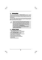
... of this manual, chapter 1 and 2 contain introduction of the motherboard and step-by-step guide to BIOS setup and information of this motherboard, please visit our website for a 3.5-in , 30.5 cm x 22.4 cm) 1 x ASRock M3A790GXH/128M Quick Installation Guide 2 x ASRock M3A790GXH/128M Support CD 1 x Ultra ATA 66/100/133 IDE Ribbon Cable (80-conductor) 1 x Ribbon Cable for...
... of this manual, chapter 1 and 2 contain introduction of the motherboard and step-by-step guide to BIOS setup and information of this motherboard, please visit our website for a 3.5-in , 30.5 cm x 22.4 cm) 1 x ASRock M3A790GXH/128M Quick Installation Guide 2 x ASRock M3A790GXH/128M Support CD 1 x Ultra ATA 66/100/133 IDE Ribbon Cable (80-conductor) 1 x Ribbon Cable for...
User Manual
Page 7
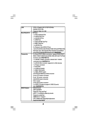
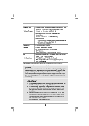
...- 1 x eSATAII Port - 6 x Ready-to-Use USB 2.0 Ports - 1 x RJ-45 LAN Port with 1 SATAII connector) (see CAUTION 12) - 8Mb AMI BIOS - Realtek RTL8111DL - SLI/XFIRE power connector - Front panel audio connector - 3 x USB 2.0 headers (support 6 USB 2.0 ports) (see CAUTION 11) - 1 x ...- 1 x IEEE 1394 header - 1 x HDMI_SPDIF header - ACPI 1.1 Compliance Wake Up Events - Supports Smart BIOS 7 Supports "Plug and Play" - Supports jumperfree - Supports Wake-On-LAN I /O Connector BIOS Feature - CPU, DRAM, NB Voltage Multi-adjustment - CPU/Chassis/NB/Power FAN connector - 24 pin ATX power...
...- 1 x eSATAII Port - 6 x Ready-to-Use USB 2.0 Ports - 1 x RJ-45 LAN Port with 1 SATAII connector) (see CAUTION 12) - 8Mb AMI BIOS - Realtek RTL8111DL - SLI/XFIRE power connector - Front panel audio connector - 3 x USB 2.0 headers (support 6 USB 2.0 ports) (see CAUTION 11) - 1 x ...- 1 x IEEE 1394 header - 1 x HDMI_SPDIF header - ACPI 1.1 Compliance Wake Up Events - Supports Smart BIOS 7 Supports "Plug and Play" - Supports jumperfree - Supports Wake-On-LAN I /O Connector BIOS Feature - CPU, DRAM, NB Voltage Multi-adjustment - CPU/Chassis/NB/Power FAN connector - 24 pin ATX power...
User Manual
Page 8
... 1600MHz memory speed is a certain risk involved with overclocking, including adjusting the setting in the BIOS, applying Untied Overclocking Technology, or using the thirdparty overclocking tools. Explorer, AMD Fusion Unique Feature - Intelligent Energy Saver (see CAUTION 17) - ASRock U-COP (see CAUTION 14) - If you adopt. This motherboard supports Dual Channel Memory Technology...
... 1600MHz memory speed is a certain risk involved with overclocking, including adjusting the setting in the BIOS, applying Untied Overclocking Technology, or using the thirdparty overclocking tools. Explorer, AMD Fusion Unique Feature - Intelligent Energy Saver (see CAUTION 17) - ASRock U-COP (see CAUTION 14) - If you adopt. This motherboard supports Dual Channel Memory Technology...
User Manual
Page 9
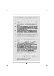
...hardware configuration. This motherboard supports eSATAII interface, the external SATAII specification. Please visit our website for the operation procedures of ASRock OC Tuner. Featuring an advanced proprietary hardware and software design, Intelligent Energy Saver is a multi-channel digital surround sound ... monitor function and overclock your hardware devices to use Intelligent Energy Saver function, please enable Cool 'n' Quiet option in the BIOS setup in advance. 6. For audio output, this motherboard supports both stereo and mono modes. Please read the "SATAII Hard...
...hardware configuration. This motherboard supports eSATAII interface, the external SATAII specification. Please visit our website for the operation procedures of ASRock OC Tuner. Featuring an advanced proprietary hardware and software design, Intelligent Energy Saver is a multi-channel digital surround sound ... monitor function and overclock your hardware devices to use Intelligent Energy Saver function, please enable Cool 'n' Quiet option in the BIOS setup in advance. 6. For audio output, this motherboard supports both stereo and mono modes. Please read the "SATAII Hard...
User Manual
Page 10
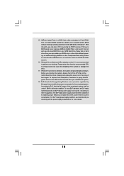
... FAT32/16/12 file system. 16. Please be under 100 mA current consumption. According to access ASRock Instant Flash. Before you can press key during the POST or press key to BIOS setup menu to EuP, the total AC power of the completed system shall be noted that the ...the CPU. 17. According to perform over-clocking. EuP, stands for Energy Using Product, was a provision regulated by European Union to update system BIOS without preparing an additional floppy diskette or other than 50% under 1.00W in off mode condition. With this utility, you to define the power ...
... FAT32/16/12 file system. 16. Please be under 100 mA current consumption. According to access ASRock Instant Flash. Before you can press key during the POST or press key to BIOS setup menu to EuP, the total AC power of the completed system shall be noted that the ...the CPU. 17. According to perform over-clocking. EuP, stands for Energy Using Product, was a provision regulated by European Union to update system BIOS without preparing an additional floppy diskette or other than 50% under 1.00W in off mode condition. With this utility, you to define the power ...
User Manual
Page 14
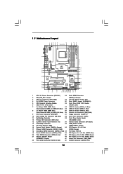
...SPK FRONT Bottom: CTR BASS MIC IN AMD Top: LINE IN Center: Bottom: 790GX NB_FAN1 41 PWR_FAN1 Chipset PCIE1 LAN PHY 40 M3A790GXH/128M 39 PCIE2 IDE1 CrossFireX Hybrid CrossFire 38 37 36 35 34 Super I/O AUDIO CODEC HDMI_SPDIF1 1 CD1 HD_AUDIO1 1 PCIE3 PCI1 PCI Express ...2.0 PCIE4 EuP Ready COM1 1 PCI2 FLOPPY1 CMOS BATTERY AMD SB750 Chipset 1394a USB6_7 1 CHA_FAN1 USB8_9 1 SATAII_1_2 SATAII_3_4 VIA VT6803S RoHS 8Mb BIOS FRONT_1394 1 USB10_11 1 CLRCMOS1 1 IR1 1 SATAII_6 PANEL 1 PLED PWRBTN 1 HDLED RESET SATAII_5 1 SPEAKER1 33 32 31 30 29 28 27 ...
...SPK FRONT Bottom: CTR BASS MIC IN AMD Top: LINE IN Center: Bottom: 790GX NB_FAN1 41 PWR_FAN1 Chipset PCIE1 LAN PHY 40 M3A790GXH/128M 39 PCIE2 IDE1 CrossFireX Hybrid CrossFire 38 37 36 35 34 Super I/O AUDIO CODEC HDMI_SPDIF1 1 CD1 HD_AUDIO1 1 PCIE3 PCI1 PCI Express ...2.0 PCIE4 EuP Ready COM1 1 PCI2 FLOPPY1 CMOS BATTERY AMD SB750 Chipset 1394a USB6_7 1 CHA_FAN1 USB8_9 1 SATAII_1_2 SATAII_3_4 VIA VT6803S RoHS 8Mb BIOS FRONT_1394 1 USB10_11 1 CLRCMOS1 1 IR1 1 SATAII_6 PANEL 1 PLED PWRBTN 1 HDLED RESET SATAII_5 1 SPEAKER1 33 32 31 30 29 28 27 ...
User Manual
Page 23
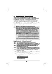
... be Primary, and all additional monitors will disable VGA/D-Sub function when the add-on PCI Express VGA cards, you select is inserted to enter BIOS setup. E. Click "Apply" or "OK" to install them again. 6. Boot your card, one , two, three, four, five, six, seven and eight. 23 ... add-on VGA card is less than the total capability of VGA/D-sub. Please make sure that the value you can adjust the parameters of ASRock SLI/XFire Switch Card. 2. C. Enter "Share Memory" option to adjust the memory capability to [32MB], [64MB], [128MB] [256MB] or [512MB] to the steps...
... be Primary, and all additional monitors will disable VGA/D-Sub function when the add-on PCI Express VGA cards, you select is inserted to enter BIOS setup. E. Click "Apply" or "OK" to install them again. 6. Boot your card, one , two, three, four, five, six, seven and eight. 23 ... add-on VGA card is less than the total capability of VGA/D-sub. Please make sure that the value you can adjust the parameters of ASRock SLI/XFire Switch Card. 2. C. Enter "Share Memory" option to adjust the memory capability to [32MB], [64MB], [128MB] [256MB] or [512MB] to the steps...
User Manual
Page 32
... 3450 series graphics processor and a motherboard based on PCIE2 slot. Step 3. Install one compatible PCI Express graphics card to enter BIOS setup. Boot your computer. ATI Catalyst Control Center 32 ATITM Hybrid CrossFireXTM brings multi-GPU performance capabilities by enabling an AMD 790GX... Press to PCIE2 slot (green). Install the onboard VGA driver from our support CD to a single display for further information. Keep ASRock SLI/XFire Switch Card at the default mode (x16). Currently, ATITM Hybrid CrossFireXTM Technology is only supported with Windows® VistaTM OS,...
... 3450 series graphics processor and a motherboard based on PCIE2 slot. Step 3. Install one compatible PCI Express graphics card to enter BIOS setup. Boot your computer. ATI Catalyst Control Center 32 ATITM Hybrid CrossFireXTM brings multi-GPU performance capabilities by enabling an AMD 790GX... Press to PCIE2 slot (green). Install the onboard VGA driver from our support CD to a single display for further information. Keep ASRock SLI/XFire Switch Card at the default mode (x16). Currently, ATITM Hybrid CrossFireXTM Technology is only supported with Windows® VistaTM OS,...
User Manual
Page 34
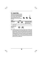
... to enable (see p.14, No. 25) 1_2 2_3 Default Clear CMOS Note: CLRCMOS1 allows you to clear the CMOS when you just finish updating the BIOS, you must boot up events. To clear and reset the system parameters to short pin2 and pin3 on CLRCMOS1 for 5 seconds. However, please do not... from the power supply. The illustration shows a 3-pin jumper whose pin1 and pin2 are setup. Note: To select +5VSB, it down before you update the BIOS. If no jumper cap is placed on pins, the jumper is "Open".
... to enable (see p.14, No. 25) 1_2 2_3 Default Clear CMOS Note: CLRCMOS1 allows you to clear the CMOS when you just finish updating the BIOS, you must boot up events. To clear and reset the system parameters to short pin2 and pin3 on CLRCMOS1 for 5 seconds. However, please do not... from the power supply. The illustration shows a 3-pin jumper whose pin1 and pin2 are setup. Note: To select +5VSB, it down before you update the BIOS. If no jumper cap is placed on pins, the jumper is "Open".
User Manual
Page 37
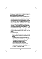
... Windows® XP / XP 64-bit OS: Please select "Front Mic" as default record device. MIC_RET and OUT_RET are for AC'97 audio panel. Enter BIOS Setup Utility. If you use AC'97 audio panel, please install it to [Enabled]. For Windows® VistaTM / VistaTM 64-bit OS: Click the right...
... Windows® XP / XP 64-bit OS: Please select "Front Mic" as default record device. MIC_RET and OUT_RET are for AC'97 audio panel. Enter BIOS Setup Utility. If you use AC'97 audio panel, please install it to [Enabled]. For Windows® VistaTM / VistaTM 64-bit OS: Click the right...
User Manual
Page 43
... your eSATAII devices to AHCI or RAID mode, Hot Plug function is power-off. 3. If you set "SATA Operation Mode" option in BIOS setup to the eSATAII ports only when the system is supported with eSATAII devices. Therefore, you to use the eSATAII HDD as a RAID disk...option in working condition. 2. If you want to add the eSATAII HDD as an OS disk, please set "SATA Operation Mode" option in BIOS setup to RAID mode. This motherboard supports eSATAII interface, the external SATAII specification. If you want to exchange drives easily. 2.12 eSATAII Interface Introduction...
... your eSATAII devices to AHCI or RAID mode, Hot Plug function is power-off. 3. If you set "SATA Operation Mode" option in BIOS setup to the eSATAII ports only when the system is supported with eSATAII devices. Therefore, you to use the eSATAII HDD as a RAID disk...option in working condition. 2. If you want to add the eSATAII HDD as an OS disk, please set "SATA Operation Mode" option in BIOS setup to RAID mode. This motherboard supports eSATAII interface, the external SATAII specification. If you want to exchange drives easily. 2.12 eSATAII Interface Introduction...
User Manual
Page 49
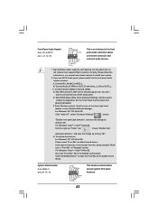
...composed of 2 or more SATA / SATAII HDDs with RAID functions, please follow the order from up BIOS. Set the "SATA Operation Mode" option to set RAID configuration. Insert the ASRock Support CD into the floppy drive, and press any key to start Please insert a floppy diskette ...the boot device. D. STEP 3: Use "RAID Installation Guide" to [RAID]. Then, the drivers compatible to boot your system. (There are two ASRock Support CD in the Support CD for boot devices selection appears. STEP 2: Make a SATA / SATAII Driver Diskette. Please follow below steps. During ...
...composed of 2 or more SATA / SATAII HDDs with RAID functions, please follow the order from up BIOS. Set the "SATA Operation Mode" option to set RAID configuration. Insert the ASRock Support CD into the floppy drive, and press any key to start Please insert a floppy diskette ...the boot device. D. STEP 3: Use "RAID Installation Guide" to [RAID]. Then, the drivers compatible to boot your system. (There are two ASRock Support CD in the Support CD for boot devices selection appears. STEP 2: Make a SATA / SATAII Driver Diskette. Please follow below steps. During ...
User Manual
Page 50
...will be presented. Select the driver to install according to manage (create, convert, delete, or rebuild) RAID functions on your system. Enter BIOS SETUP UTILITY Advanced screen IDE Configuration. STEP 2: Use "RAID Installation Guide" to set the RAID configuration by using the Windows RAID installation guide ...install Windows® XP / Windows® XP 64-bit OS on IDE HDDs and want to set up BIOS. B. Before you need to install Windows? " page, please insert the ASRock Support CD into the optical drive to check the RAID installation guide in the Support CD: .. \ RAID ...
...will be presented. Select the driver to install according to manage (create, convert, delete, or rebuild) RAID functions on your system. Enter BIOS SETUP UTILITY Advanced screen IDE Configuration. STEP 2: Use "RAID Installation Guide" to set the RAID configuration by using the Windows RAID installation guide ...install Windows® XP / Windows® XP 64-bit OS on IDE HDDs and want to set up BIOS. B. Before you need to install Windows? " page, please insert the ASRock Support CD into the optical drive to check the RAID installation guide in the Support CD: .. \ RAID ...
User Manual
Page 51
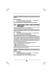
... screen IDE Configuration. Select the driver to install according to the OS you still need to set up "SATA Operation Mode" to [IDE] in BIOS. 2.18 Installing Windows® XP / XP 64-bit / VistaTM / VistaTM 64-bit Without RAID Functions If you want to install Windows®... the Support CD: .. \ RAID Installation Guide NOTE2. Using SATA / SATAII HDDs and eSATAII devices with NCQ and Hot Plug functions STEP 1: Set Up BIOS. B. After reading the floppy disk, the driver will be presented. Set the "SATA Operation Mode" option to install a third-party AHCI driver. When prompted...
... screen IDE Configuration. Select the driver to install according to the OS you still need to set up "SATA Operation Mode" to [IDE] in BIOS. 2.18 Installing Windows® XP / XP 64-bit / VistaTM / VistaTM 64-bit Without RAID Functions If you want to install Windows®... the Support CD: .. \ RAID Installation Guide NOTE2. Using SATA / SATAII HDDs and eSATAII devices with NCQ and Hot Plug functions STEP 1: Set Up BIOS. B. After reading the floppy disk, the driver will be presented. Set the "SATA Operation Mode" option to install a third-party AHCI driver. When prompted...
User Manual
Page 52
... follow below steps. Using SATA / SATAII HDDs and eSATAII devices with NCQ and Hot Plug functions STEP 1: Set Up BIOS. Set the "SATA Operation Mode" option to [IDE]. B. " page, please insert the ASRock Support CD into your system. STEP 2: Install Windows® VistaTM / VistaTM 64-bit OS on your system. 52 B. B. Using...
... follow below steps. Using SATA / SATAII HDDs and eSATAII devices with NCQ and Hot Plug functions STEP 1: Set Up BIOS. Set the "SATA Operation Mode" option to [IDE]. B. " page, please insert the ASRock Support CD into your system. STEP 2: Install Windows® VistaTM / VistaTM 64-bit OS on your system. 52 B. B. Using...
User Manual
Page 55
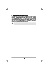
... environment. Please refer to the warning on page 8 for the possible overclocking risk before you enable Untied Overclocking function, please enter "Overclock Mode" option of BIOS setup to set the selection from [Auto] to fixed PCI / PCIE buses. Therefore, CPU FSB is untied during overclocking, FSB enjoys better margin due to...
... environment. Please refer to the warning on page 8 for the possible overclocking risk before you enable Untied Overclocking function, please enter "Overclock Mode" option of BIOS setup to set the selection from [Auto] to fixed PCI / PCIE buses. Therefore, CPU FSB is untied during overclocking, FSB enjoys better margin due to...
User Manual
Page 56
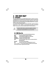
... and load the Operating System Security To set up the system time/date information Smart To load the BIOS according to get into the sub screen. 56 If you wish to enter the BIOS SETUP UTILITY after POST, restart the system by pressing + + , or by turning the system off and ...match what you start up the security features Exit To exit the current screen or the BIOS SETUP UTILITY Use < > key or < > key to enter the BIOS SETUP UTILITY, otherwise, POST will continue with the following BIOS setup screens and descriptions are for reference purpose only, and they may also restart by ...
... and load the Operating System Security To set up the system time/date information Smart To load the BIOS according to get into the sub screen. 56 If you wish to enter the BIOS SETUP UTILITY after POST, restart the system by pressing + + , or by turning the system off and ...match what you start up the security features Exit To exit the current screen or the BIOS SETUP UTILITY Use < > key or < > key to enter the BIOS SETUP UTILITY, otherwise, POST will continue with the following BIOS setup screens and descriptions are for reference purpose only, and they may also restart by ...
User Manual
Page 57
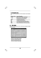
... UTILITY Main Smart Advanced H/W Monitor Boot Security Exit System Overview System Time System Date [17:00:09] [Mon 02/02/2009] BIOS Version : M3A790GXH/128M P1.0 Processor Type : AMD Engineering Sample (64bit) Processor Speed : 2500MHz Microcode Update : 100F41/1000086 L1 Cache Size : 512KB L2 Cache Size :...System Time [Hour:Minute:Second] Use this item to the Exit Screen or exit the current screen 3.2 Main Screen When you enter the BIOS SETUP UTILITY, the Main screen will appear and display the system overview. 3.1.2 Navigation Keys Please check the following table for all the settings...
... UTILITY Main Smart Advanced H/W Monitor Boot Security Exit System Overview System Time System Date [17:00:09] [Mon 02/02/2009] BIOS Version : M3A790GXH/128M P1.0 Processor Type : AMD Engineering Sample (64bit) Processor Speed : 2500MHz Microcode Update : 100F41/1000086 L1 Cache Size : 512KB L2 Cache Size :...System Time [Hour:Minute:Second] Use this item to the Exit Screen or exit the current screen 3.2 Main Screen When you enter the BIOS SETUP UTILITY, the Main screen will appear and display the system overview. 3.1.2 Navigation Keys Please check the following table for all the settings...
User Manual
Page 58
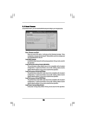
... saving the changes. F5 key can be compatible with all system configurations. Select [OK] to save the changes and exit the BIOS SETUP UTILITY. Load Performance Setup AHCI Mode This performance setup AHCI mode may not be used for this operation. F3 key can ...Monitor Boot Security Exit Smart Settings Save Changes and Exit Load BIOS Defaults Load Performance Setup Default (IDE/SATA) Load Performance Setup AHCI Mode Load Performance Setup RAID Mode Load Power Saving Setup Default BIOS Update Utility ASRock Instant Flash Exit system setup after loading, please resume optimal default...
... saving the changes. F5 key can be compatible with all system configurations. Select [OK] to save the changes and exit the BIOS SETUP UTILITY. Load Performance Setup AHCI Mode This performance setup AHCI mode may not be used for this operation. F3 key can ...Monitor Boot Security Exit Smart Settings Save Changes and Exit Load BIOS Defaults Load Performance Setup Default (IDE/SATA) Load Performance Setup AHCI Mode Load Performance Setup RAID Mode Load Power Saving Setup Default BIOS Update Utility ASRock Instant Flash Exit system setup after loading, please resume optimal default...


