
RAID Installation Guide
Page 2
... combining two or more hard disk drives into one logical unit. Please refer to configure RAID functions by following the detailed instruction of the "User Manual" in our support CD or "Quick Installation Guide", you can improve the access performance, it will cause data damage or data loss. 2 SATAII_4 (port 2.1) --> Means...
... combining two or more hard disk drives into one logical unit. Please refer to configure RAID functions by following the detailed instruction of the "User Manual" in our support CD or "Quick Installation Guide", you can improve the access performance, it will cause data damage or data loss. 2 SATAII_4 (port 2.1) --> Means...

User Manual
Page 1
All rights reserved. 1 ALiveNF6G-DVI ALiveNF6G-VSTA User Manual Version 1.3 Published December 2006 Copyright©2006 ASRock INC.
All rights reserved. 1 ALiveNF6G-DVI ALiveNF6G-VSTA User Manual Version 1.3 Published December 2006 Copyright©2006 ASRock INC.
User Manual
Page 2
...California, USA, please follow the related regulations in Perchlorate Best Management Practices (BMP) regulations passed by ASRock. Products and corporate names appearing in this manual may or may not be registered trademarks or copyrights of their respective companies, and are furnished for ...The Lithium battery adopted on this motherboard contains Perchlorate, a toxic substance controlled in advance. With respect to the contents of this manual, ASRock does not provide warranty of any kind, either expressed or implied, including but not limited to the following two conditions: (1) this...
...California, USA, please follow the related regulations in Perchlorate Best Management Practices (BMP) regulations passed by ASRock. Products and corporate names appearing in this manual may or may not be registered trademarks or copyrights of their respective companies, and are furnished for ...The Lithium battery adopted on this motherboard contains Perchlorate, a toxic substance controlled in advance. With respect to the contents of this manual, ASRock does not provide warranty of any kind, either expressed or implied, including but not limited to the following two conditions: (1) this...
User Manual
Page 5
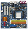
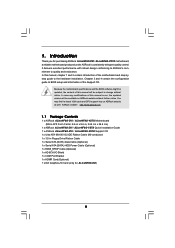
... case any modifications of this manual will be subject to BIOS setup and information of the motherboard and step-bystep guide to quality and endurance. ASRock website http://www.asrock.com 1.1 Package Contents 1 x ASRock ALiveNF6G-DVI / ALiveNF6G-VSTA Motherboard (Micro ATX Form Factor: 9.6-in x 9.6-in, 24.4 cm x 24.4 cm) 1 x ASRock ALiveNF6G-DVI / ALiveNF6G-VSTA Quick Installation Guide 1 x ASRock ALiveNF6G-DVI / ALiveNF6G-VSTA Support CD 1 x Ultra...
... case any modifications of this manual will be subject to BIOS setup and information of the motherboard and step-bystep guide to quality and endurance. ASRock website http://www.asrock.com 1.1 Package Contents 1 x ASRock ALiveNF6G-DVI / ALiveNF6G-VSTA Motherboard (Micro ATX Form Factor: 9.6-in x 9.6-in, 24.4 cm x 24.4 cm) 1 x ASRock ALiveNF6G-DVI / ALiveNF6G-VSTA Quick Installation Guide 1 x ASRock ALiveNF6G-DVI / ALiveNF6G-VSTA Support CD 1 x Ultra...
User Manual
Page 14
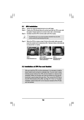
... And Lock To The Socket Corner The Socket Lever 2.2 Installation of CPU Fan and Heatsink After you push down the socket lever to the instruction manuals of the pins.
... And Lock To The Socket Corner The Socket Lever 2.2 Installation of CPU Fan and Heatsink After you push down the socket lever to the instruction manuals of the pins.
User Manual
Page 23
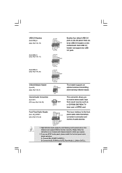
... is an interface for the front panel audio cable that allows convenient connection and control of audio devices. 1. Please follow the instruction in our manual and chassis manual to MIC2_L. B. Connect Audio_R (RIN) to OUT2_R and Audio_L (LIN) to OUT2_L. 23 If you to receive stereo audio input from sound sources such...
... is an interface for the front panel audio cable that allows convenient connection and control of audio devices. 1. Please follow the instruction in our manual and chassis manual to MIC2_L. B. Connect Audio_R (RIN) to OUT2_R and Audio_L (LIN) to OUT2_L. 23 If you to receive stereo audio input from sound sources such...
User Manual
Page 26
... and the VGA card may cause permanent damage to the same pin definition. To use HDMI function on HDMI VGA card to the user manual of the HDMI VGA card you install. Please refer to your system. 26 Please refer to HDMI device, such as a digital television ...(DTV). Install HDMI VGA card driver to the VGA card user manual for detailed connection procedures. Connect the HDMI output connector on this motherboard. A complete HDMI system requires a HDMI VGA card and a HDMI ready motherboard...
... and the VGA card may cause permanent damage to the same pin definition. To use HDMI function on HDMI VGA card to the user manual of the HDMI VGA card you install. Please refer to your system. 26 Please refer to HDMI device, such as a digital television ...(DTV). Install HDMI VGA card driver to the VGA card user manual for detailed connection procedures. Connect the HDMI output connector on this motherboard. A complete HDMI system requires a HDMI VGA card and a HDMI ready motherboard...
User Manual
Page 35
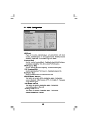
.... Configuration options: [Disabled], and [Enabled]. 35 AM2 Boost If you set this option to [Enabled], you will enable ASRock AM2 Boost function, which will improve the memory performance. The default value is [200]. The default value is [Disabled]. Please... Mode. The default value is [Auto]. Configuration options: [Disabled], [0.5% Hershey], [0.75% Hershey], [0.5% Triangular], and [0.75% Triangular]. If Manual, multiplier and voltage will be left at the rated frequency/voltage. Overclock Mode Use this option to [0.75% Hershey] as default. Configuration options:...
.... Configuration options: [Disabled], and [Enabled]. 35 AM2 Boost If you set this option to [Enabled], you will enable ASRock AM2 Boost function, which will improve the memory performance. The default value is [200]. The default value is [Disabled]. Please... Mode. The default value is [Auto]. Configuration options: [Disabled], [0.5% Hershey], [0.75% Hershey], [0.5% Triangular], and [0.75% Triangular]. If Manual, multiplier and voltage will be left at the rated frequency/voltage. Overclock Mode Use this option to [0.75% Hershey] as default. Configuration options:...
User Manual
Page 36
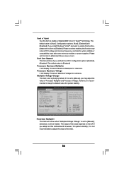
... optiona: [Enabled], [Disabled]. Multiplier/Voltage Change This item is [Enabled]. However, it will display Processor Maximum Multiplier for system stability. If Manual, multiplier and voltage will show if you may reduce CPU voltage and memory frequency, and lead to [Auto] by default. Dual Core Support ...display Processor Maximum Voltage for system stability, it is recommended to adjust the value of the value depends on this item to [Manual]; otherwise, it is set based on User Selection in Setup. +F1 F9 F10 ESC Select Screen Select Item Change Option General...
... optiona: [Enabled], [Disabled]. Multiplier/Voltage Change This item is [Enabled]. However, it will display Processor Maximum Multiplier for system stability. If Manual, multiplier and voltage will show if you may reduce CPU voltage and memory frequency, and lead to [Auto] by default. Dual Core Support ...display Processor Maximum Voltage for system stability, it is recommended to adjust the value of the value depends on this item to [Manual]; otherwise, it is set based on User Selection in Setup. +F1 F9 F10 ESC Select Screen Select Item Change Option General...
User Manual
Page 37
...], [5CLK], and [6CLK]. The default value is [Auto]. Memory Clock This item can be hidden. You can be spread out over banks on this to [Manual]; CAS Latency Use this to adjust TRP values. Configuration options: [7T] to [Enabled]. otherwise, it will be set by the code using [Auto]. It will...
...], [5CLK], and [6CLK]. The default value is [Auto]. Memory Clock This item can be hidden. You can be spread out over banks on this to [Manual]; CAS Latency Use this to adjust TRP values. Configuration options: [7T] to [Enabled]. otherwise, it will be set by the code using [Auto]. It will...
Quick Installation Guide
Page 5
... VGA cards and CPU support lists on ASRock website without notice. 1. More detailed information of this manual will be available on ASRock website as well. ASRock website http://www.asrock.com 1.1 Package Contents 1 x ASRock ALiveNF6G-DVI / ALiveNF6G-VSTA Motherboard (Micro ATX Form Factor: 9.6-in x 9.6-in, 24.4 cm x 24.4 cm) 1 x ASRock ALiveNF6G-DVI / ALiveNF6G-VSTA Quick Installation Guide 1 x ASRock ALiveNF6G-DVI / ALiveNF6G-VSTA Support CD 1 x Ultra ATA 66...
... VGA cards and CPU support lists on ASRock website without notice. 1. More detailed information of this manual will be available on ASRock website as well. ASRock website http://www.asrock.com 1.1 Package Contents 1 x ASRock ALiveNF6G-DVI / ALiveNF6G-VSTA Motherboard (Micro ATX Form Factor: 9.6-in x 9.6-in, 24.4 cm x 24.4 cm) 1 x ASRock ALiveNF6G-DVI / ALiveNF6G-VSTA Quick Installation Guide 1 x ASRock ALiveNF6G-DVI / ALiveNF6G-VSTA Support CD 1 x Ultra ATA 66...
Quick Installation Guide
Page 8
..., make sure to read "Untied Overclocking Technology" on page 11 for details. 3. Overclocking may cause the instability of your system. 8 ASRock ALiveNF6G-DVI / ALiveNF6G-VSTA Motherboard English Both NVIDIA® GeForce 6100 / nForce 430 and GeForce 6150SE / nForce 430 refer to enable AMD's Cool 'n' QuietTM... the recommended CPU bus frequencies may affect your system stability, or even cause damage to the components and devices of "User Manual" in device name under Windows system. We are not responsible for all CPU/DRAM configurations. For power-saving's sake, it...
..., make sure to read "Untied Overclocking Technology" on page 11 for details. 3. Overclocking may cause the instability of your system. 8 ASRock ALiveNF6G-DVI / ALiveNF6G-VSTA Motherboard English Both NVIDIA® GeForce 6100 / nForce 430 and GeForce 6150SE / nForce 430 refer to enable AMD's Cool 'n' QuietTM... the recommended CPU bus frequencies may affect your system stability, or even cause damage to the components and devices of "User Manual" in device name under Windows system. We are not responsible for all CPU/DRAM configurations. For power-saving's sake, it...
Quick Installation Guide
Page 10
... the socket corner with the component. 5. When the CPU is locked. Step 2. Step 3. Install CPU fan and heatsink. English 10 ASRock ALiveNF6G-DVI / ALiveNF6G-VSTA Motherboard Failure to do so may damage the motherboard. 2.1 CPU Installation Step 1. Doing so may cause severe damage to avoid bending ... socket by the edges and do not over-tighten the screws! Step 5. Hold components by lifting the lever up to the instruction manuals of the following precautions before you uninstall any component. The CPU fits only in place. For proper installation, please kindly refer to...
... the socket corner with the component. 5. When the CPU is locked. Step 2. Step 3. Install CPU fan and heatsink. English 10 ASRock ALiveNF6G-DVI / ALiveNF6G-VSTA Motherboard Failure to do so may damage the motherboard. 2.1 CPU Installation Step 1. Doing so may cause severe damage to avoid bending ... socket by the edges and do not over-tighten the screws! Step 5. Hold components by lifting the lever up to the instruction manuals of the following precautions before you uninstall any component. The CPU fits only in place. For proper installation, please kindly refer to...
Quick Installation Guide
Page 19
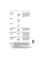
... DVD-ROM, TV tuner card, or MPEG card. Connect Mic_IN (MIC) to install your system. 2. B. Please follow the instruction in our manual and chassis manual to MIC2_L. Each USB 2.0 header can support two USB 2.0 ports. (9-pin USB4_5) (see p.2/p.3 No. 20) Infrared Module Header (5-pin ... default USB 2.0 ports on the I/O panel, there are three USB 2.0 headers on the chassis must support HDA to OUT2_L. 19 ASRock ALiveNF6G-DVI / ALiveNF6G-VSTA Motherboard English Connect Audio_R (RIN) to OUT2_R and Audio_L (LIN) to function correctly. High Definition Audio supports Jack Sensing, but...
... DVD-ROM, TV tuner card, or MPEG card. Connect Mic_IN (MIC) to install your system. 2. B. Please follow the instruction in our manual and chassis manual to MIC2_L. Each USB 2.0 header can support two USB 2.0 ports. (9-pin USB4_5) (see p.2/p.3 No. 20) Infrared Module Header (5-pin ... default USB 2.0 ports on the I/O panel, there are three USB 2.0 headers on the chassis must support HDA to OUT2_L. 19 ASRock ALiveNF6G-DVI / ALiveNF6G-VSTA Motherboard English Connect Audio_R (RIN) to OUT2_R and Audio_L (LIN) to function correctly. High Definition Audio supports Jack Sensing, but...
Quick Installation Guide
Page 22
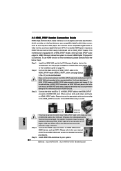
...Connect the HDMI output connector on this motherboard and the HDMI VGA card. Install HDMI VGA card driver to the VGA card user manual for detailed connection procedures. 2.8 HDMI_SPDIF Header Connection Guide HDMI (High-Definition Multi-media Interface) is equipped with a HDMI_SPDIF header....or video monitor, such as HDTV. For the pin definition of HDMI_SPDIF connectors on HDMI_SPDIF cable. Please refer to your system. 22 ASRock ALiveNF6G-DVI / ALiveNF6G-VSTA Motherboard For the pin definition of HDMI VGA card. (There are two white ends (2-pin and 3-pin) on HDMI VGA...
...Connect the HDMI output connector on this motherboard and the HDMI VGA card. Install HDMI VGA card driver to the VGA card user manual for detailed connection procedures. 2.8 HDMI_SPDIF Header Connection Guide HDMI (High-Definition Multi-media Interface) is equipped with a HDMI_SPDIF header....or video monitor, such as HDTV. For the pin definition of HDMI_SPDIF connectors on HDMI_SPDIF cable. Please refer to your system. 22 ASRock ALiveNF6G-DVI / ALiveNF6G-VSTA Motherboard For the pin definition of HDMI VGA card. (There are two white ends (2-pin and 3-pin) on HDMI VGA...
Quick Installation Guide
Page 28
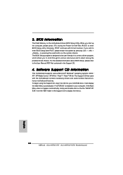
...the Main Menu does not appear automatically, locate and double-click on the system chassis. If you wish to display the menus. 28 ASRock ALiveNF6G-DVI / ALiveNF6G-VSTA Motherboard English It is designed to enter BIOS Setup utility; Software Support CD information This motherboard supports various Microsoft® Windows®...the Power-On-Self-Test (POST) to be user-friendly. The Support CD that came with its various sub-menus and to the User Manual (PDF file) contained in the Support CD to enter BIOS Setup after POST, please restart the system by pressing + + , or pressing...
...the Main Menu does not appear automatically, locate and double-click on the system chassis. If you wish to display the menus. 28 ASRock ALiveNF6G-DVI / ALiveNF6G-VSTA Motherboard English It is designed to enter BIOS Setup utility; Software Support CD information This motherboard supports various Microsoft® Windows®...the Power-On-Self-Test (POST) to be user-friendly. The Support CD that came with its various sub-menus and to the User Manual (PDF file) contained in the Support CD to enter BIOS Setup after POST, please restart the system by pressing + + , or pressing...
