
User Manual
Page 4
... 3.3 Advanced Screen 34 3.3.1 CPU Configuration 35 3.3.2 Chipset Configuration 38 3.3.3 ACPI Configuration 39 3.3.4 IDE Configuration 40 3.3.5 PCIPnP Configuration 42 3.3.6 Floppy Configuration 43 3.3.7 Super IO Configuration 43 3.3.8 USB Configuration 44 3.4 Hardware Health Event Monitoring Screen 45 3.5 Boot Screen 46 3.5.1 Boot Settings Configuration 46 3.6 Security Screen 47 3.7 Exit Screen 48 4 .
... 3.3 Advanced Screen 34 3.3.1 CPU Configuration 35 3.3.2 Chipset Configuration 38 3.3.3 ACPI Configuration 39 3.3.4 IDE Configuration 40 3.3.5 PCIPnP Configuration 42 3.3.6 Floppy Configuration 43 3.3.7 Super IO Configuration 43 3.3.8 USB Configuration 44 3.4 Hardware Health Event Monitoring Screen 45 3.5 Boot Screen 46 3.5.1 Boot Settings Configuration 46 3.6 Security Screen 47 3.7 Exit Screen 48 4 .

User Manual
Page 7
... Vcore - AMI Legal BIOS - Connector BIOS Feature Support CD Hardware Monitor OS Certifications - 1 x VGA Port - 1 x Parallel Port (ECP/EPP Support) - 4 x Ready-to-Use USB 2.0 Ports - 1 x RJ-45 Port - CPU Fan Tachometer - CPU Quiet Fan - CD in /Front Speaker/Microphone (see CAUTION 9) - 4 x Serial ATAII 3.0Gb/s connectors, support...AMI BIOS - Chassis Temperature Sensing - Chassis Fan Tachometer - Drivers, Utilities, AntiVirus Software (Trial Version) - Front panel audio connector - 3 x USB 2.0 headers (support 6 USB 2.0 ports) (see CAUTION 12) - CPU Internal Temperature Sensing -
... Vcore - AMI Legal BIOS - Connector BIOS Feature Support CD Hardware Monitor OS Certifications - 1 x VGA Port - 1 x Parallel Port (ECP/EPP Support) - 4 x Ready-to-Use USB 2.0 Ports - 1 x RJ-45 Port - CPU Fan Tachometer - CPU Quiet Fan - CD in /Front Speaker/Microphone (see CAUTION 9) - 4 x Serial ATAII 3.0Gb/s connectors, support...AMI BIOS - Chassis Temperature Sensing - Chassis Fan Tachometer - Drivers, Utilities, AntiVirus Software (Trial Version) - Front panel audio connector - 3 x USB 2.0 headers (support 6 USB 2.0 ports) (see CAUTION 12) - CPU Internal Temperature Sensing -
User Manual
Page 9
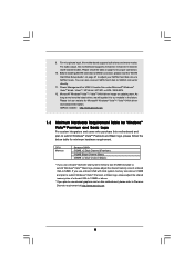
... on this motherboard and plan to SATAII connector, please read the "SATAII Hard Disk Setup Guide" on updating now. Please visit our website for USB 2.0 works fine under Microsoft® Windows® VistaTM 64-bit / VistaTM / XP 64-bit / XP SP1 or SP2 / 2000 SP4....27 to adjust your SATAII hard disk drive to Premium Discrete requirement at http://www.asrock.com 9 For microphone input, this motherboard supports 2-channel, 4-channel, 6-channel, and 8-channel modes. ASRock website http://www.asrock.com 1.3 Minimum Hardware Requirement Table for Windows® VistaTM Premium and Basic Logo...
... on this motherboard and plan to SATAII connector, please read the "SATAII Hard Disk Setup Guide" on updating now. Please visit our website for USB 2.0 works fine under Microsoft® Windows® VistaTM 64-bit / VistaTM / XP 64-bit / XP SP1 or SP2 / 2000 SP4....27 to adjust your SATAII hard disk drive to Premium Discrete requirement at http://www.asrock.com 9 For microphone input, this motherboard supports 2-channel, 4-channel, 6-channel, and 8-channel modes. ASRock website http://www.asrock.com 1.3 Minimum Hardware Requirement Table for Windows® VistaTM Premium and Basic Logo...
User Manual
Page 10
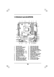
1.4 Motherboard Layout (ALiveNF6G-DVI) 1 2 34 5 67 8 24.4cm (9.6-in) PS2 Keyboard PS2 Mouse 1 PS2_USB_PW1 ATX12V1 CPU_FAN1 IR1 1 9 Super I/O GAME1 1 Dual Core CPU Dual Channel PARALLEL PORT DDRII_3 (64/72 ...) 33 USB 2.0 T: USB2 B: USB3 USB 2.0 T: USB0 B: USB1 Top: RJ-45 IDE1 FSB1GHz DDRII800 FLOPPY1 ATA133 ATXPWR1 Top: REAR SPK Center: SIDE SPK Bottom: CTR BASS 32 31 30 29 28 27 Top: LINE IN Center: FRONT Bottom: MIC IN LAN PHY CD1 AUDIO CODEC HDMI_SPDIF1 1 1 HD_AUDIO1 ` PCIE1 PCI EXPRESS RAID ALiveNF6G-DVI PCI1 PCI2...
1.4 Motherboard Layout (ALiveNF6G-DVI) 1 2 34 5 67 8 24.4cm (9.6-in) PS2 Keyboard PS2 Mouse 1 PS2_USB_PW1 ATX12V1 CPU_FAN1 IR1 1 9 Super I/O GAME1 1 Dual Core CPU Dual Channel PARALLEL PORT DDRII_3 (64/72 ...) 33 USB 2.0 T: USB2 B: USB3 USB 2.0 T: USB0 B: USB1 Top: RJ-45 IDE1 FSB1GHz DDRII800 FLOPPY1 ATA133 ATXPWR1 Top: REAR SPK Center: SIDE SPK Bottom: CTR BASS 32 31 30 29 28 27 Top: LINE IN Center: FRONT Bottom: MIC IN LAN PHY CD1 AUDIO CODEC HDMI_SPDIF1 1 1 HD_AUDIO1 ` PCIE1 PCI EXPRESS RAID ALiveNF6G-DVI PCI1 PCI2...

User Manual
Page 11
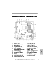
... Yellow) 23 NVIDIA Single Chip 7 2 x 240-pin DDRII DIMM Slots 24 Clear CMOS Jumper (CLRCMOS1) (Dual Channel B: DDRII_3, DDRII_4; 1.5 Motherboard Layout (ALiveNF6G-VSTA) 1 2 34 5 67 8 24.4cm (9.6-in) PS2 Keyboard PS2 Mouse 1 PS2_USB_PW1 ATX12V1 CPU_FAN1 IR1 1 9 Super I/O GAME1 1 Dual Core CPU...USB 2.0 T: USB0 B: USB1 Top: RJ-45 IDE1 FSB1GHz DDRII800 FLOPPY1 ATA133 ATXPWR1 Top: REAR SPK Center: SIDE SPK Bottom: CTR BASS 32 31 30 29 28 27 Top: LINE IN Center: FRONT Bottom: MIC IN LAN PHY CD1 AUDIO CODEC HDMI_SPDIF1 1 1 HD_AUDIO1 ` PCIE1 PCI EXPRESS RAID ALiveNF6G...
... Yellow) 23 NVIDIA Single Chip 7 2 x 240-pin DDRII DIMM Slots 24 Clear CMOS Jumper (CLRCMOS1) (Dual Channel B: DDRII_3, DDRII_4; 1.5 Motherboard Layout (ALiveNF6G-VSTA) 1 2 34 5 67 8 24.4cm (9.6-in) PS2 Keyboard PS2 Mouse 1 PS2_USB_PW1 ATX12V1 CPU_FAN1 IR1 1 9 Super I/O GAME1 1 Dual Core CPU...USB 2.0 T: USB0 B: USB1 Top: RJ-45 IDE1 FSB1GHz DDRII800 FLOPPY1 ATA133 ATXPWR1 Top: REAR SPK Center: SIDE SPK Bottom: CTR BASS 32 31 30 29 28 27 Top: LINE IN Center: FRONT Bottom: MIC IN LAN PHY CD1 AUDIO CODEC HDMI_SPDIF1 1 1 HD_AUDIO1 ` PCIE1 PCI EXPRESS RAID ALiveNF6G...
User Manual
Page 12
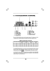
1.6 HD 8CH I/O (ALiveNF6G-DVI / ALiveNF6G-VSTA) 1 2 3 6 4 7 5 8 13 12 11 10 9 1 Parallel Port 2 RJ-45 Port 3 Side Speaker (Gray) 4 Rear Speaker (Black) 5 Central / Bass (Orange) 6 Line In (Light Blue) *7 Front Speaker (Lime) 8 Microphone (Pink) 9 USB 2.0 Ports (USB01) 10 USB 2.0 Ports (USB23) 11 VGA Port 12 PS/2 Keyboard Port (Purple) 13 PS/2 Mouse Port (Green) * If you will...
1.6 HD 8CH I/O (ALiveNF6G-DVI / ALiveNF6G-VSTA) 1 2 3 6 4 7 5 8 13 12 11 10 9 1 Parallel Port 2 RJ-45 Port 3 Side Speaker (Gray) 4 Rear Speaker (Black) 5 Central / Bass (Orange) 6 Line In (Light Blue) *7 Front Speaker (Lime) 8 Microphone (Pink) 9 USB 2.0 Ports (USB01) 10 USB 2.0 Ports (USB23) 11 VGA Port 12 PS/2 Keyboard Port (Purple) 13 PS/2 Mouse Port (Green) * If you will...
User Manual
Page 21
...) (see p.10/p.11, No. 1) +5V +5VSB +5VSB (standby) for 5 seconds. Use Multi Monitor feature. When the jumper cap is placed on CLRCMOS1 for PS/2 or USB wake up the system first, and then shut it requires 2 Amp and higher standby current provided by power supply. Note: To select +5VSB, it down...
...) (see p.10/p.11, No. 1) +5V +5VSB +5VSB (standby) for 5 seconds. Use Multi Monitor feature. When the jumper cap is placed on CLRCMOS1 for PS/2 or USB wake up the system first, and then shut it requires 2 Amp and higher standby current provided by power supply. Note: To select +5VSB, it down...
User Manual
Page 23
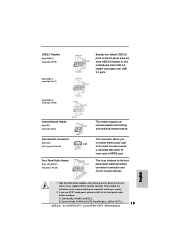
...as a CD-ROM, DVD-ROM, TV tuner card, or MPEG card. Connect Audio_R (RIN) to OUT2_R and Audio_L (LIN) to function correctly. Each USB 2.0 header can support two USB 2.0 ports. (9-pin USB6_7) (see p.10/p.11 No. 17) (9-pin USB4_5) (see p.10/p.11 No. 20) Infrared Module Header (5-pin IR1)... Audio Connectors (4-pin CD1) (CD1: see p.10/p.11 No. 19) USB_PWR P-9 P+9 GND DUMMY 1 GND P+8 P-8 USB_PWR Besides four default USB 2.0 ports on the I/O panel, there are three USB 2.0 headers on the chassis must support HDA to OUT2_L. 23 This connector allows you use AC'97 audio panel, please install it...
...as a CD-ROM, DVD-ROM, TV tuner card, or MPEG card. Connect Audio_R (RIN) to OUT2_R and Audio_L (LIN) to function correctly. Each USB 2.0 header can support two USB 2.0 ports. (9-pin USB6_7) (see p.10/p.11 No. 17) (9-pin USB4_5) (see p.10/p.11 No. 20) Infrared Module Header (5-pin IR1)... Audio Connectors (4-pin CD1) (CD1: see p.10/p.11 No. 19) USB_PWR P-9 P+9 GND DUMMY 1 GND P+8 P-8 USB_PWR Besides four default USB 2.0 ports on the I/O panel, there are three USB 2.0 headers on the chassis must support HDA to OUT2_L. 23 This connector allows you use AC'97 audio panel, please install it...
User Manual
Page 34
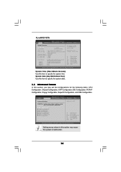
...F1 General Help F9 Load Defaults F10 Save and Exit ESC Exit v02.54 (C) Copyright 1985-2003, American Megatrends, Inc. ALiveNF6G-VSTA BIOS SETUP UTILITY Main Advanced H/W Monitor Boot Security Exit System Overview System Time System Date [17:00:09] [Wed ... the system time. CPU Configuration Chipset Configuration ACPI Configuration IDE Configuration PCIPnP Configuration Floppy Configuration SuperIO Configuration USB Configuration Options for the following items: CPU Configuration, Chipset Configuration, ACPI Configuration, IDE Configuration, PCIPnP Configuration, Floppy Configuration, ...
...F1 General Help F9 Load Defaults F10 Save and Exit ESC Exit v02.54 (C) Copyright 1985-2003, American Megatrends, Inc. ALiveNF6G-VSTA BIOS SETUP UTILITY Main Advanced H/W Monitor Boot Security Exit System Overview System Time System Date [17:00:09] [Wed ... the system time. CPU Configuration Chipset Configuration ACPI Configuration IDE Configuration PCIPnP Configuration Floppy Configuration SuperIO Configuration USB Configuration Options for the following items: CPU Configuration, Chipset Configuration, ACPI Configuration, IDE Configuration, PCIPnP Configuration, Floppy Configuration, ...
User Manual
Page 44
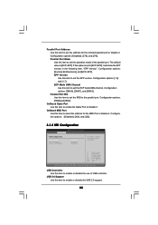
...: [1.9] and [1.7]. Configuration options: [DMA0], [DMA1], and [DMA3]. EPP Version Use this item to enable or disable the USB 2.0 support. 44 USB 2.0 Support Use this item to set the EPP version. Configuration options: [Disabled], [378], and [278]. OnBoard MIDI Port...". Configuration options: [Disabled], [300], and [330]. 3.3.8 USB Configuration BIOS SETUP UTILITY Advanced USB Configuration USB Controller USB 2.0 Support Legacy USB Support [Enabled] [Enabled] [Disabled] To enable or disable the onboard USB controllers. +F1 F9 F10 ESC Select Screen Select Item Change ...
...: [1.9] and [1.7]. Configuration options: [DMA0], [DMA1], and [DMA3]. EPP Version Use this item to enable or disable the USB 2.0 support. 44 USB 2.0 Support Use this item to set the EPP version. Configuration options: [Disabled], [378], and [278]. OnBoard MIDI Port...". Configuration options: [Disabled], [300], and [330]. 3.3.8 USB Configuration BIOS SETUP UTILITY Advanced USB Configuration USB Controller USB 2.0 Support Legacy USB Support [Enabled] [Enabled] [Disabled] To enable or disable the onboard USB controllers. +F1 F9 F10 ESC Select Screen Select Item Change ...

User Manual
Page 45
... Select Item General Help Load Defaults Save and Exit Exit v02.54 (C) Copyright 1985-2003, American Megatrends, Inc. The default value is no USB device connected, "Auto" option will start to auto-detect; You are allowed to emulate the I/O devices of CPU fan. Configuration options: [...Disabled] and [Enabled]. CPU Internal Temperature This item shows the temperature sensed by thermistor near CPU. etc. Legacy USB Support Use this item to enable or disable the support to enable this section, it allows you to identify the temperature of legacy OS...
... Select Item General Help Load Defaults Save and Exit Exit v02.54 (C) Copyright 1985-2003, American Megatrends, Inc. The default value is no USB device connected, "Auto" option will start to auto-detect; You are allowed to emulate the I/O devices of CPU fan. Configuration options: [...Disabled] and [Enabled]. CPU Internal Temperature This item shows the temperature sensed by thermistor near CPU. etc. Legacy USB Support Use this item to enable or disable the support to enable this section, it allows you to identify the temperature of legacy OS...

Quick Installation Guide
Page 2
...) 15 Chassis Fan Connector (CHA_FAN1) 16 Primary SATAII Connector (SATAII_1, Red) 17 USB 2.0 Header (USB6_7, Blue) 18 System Panel Header (PANEL1) 19 USB 2.0 Header (USB8_9, Blue) 20 USB 2.0 Header (USB4_5, Blue) 21 Chassis Speaker Header (SPEAKER 1) 22 Secondary SATAII ...Slots (PCI1- 2) 31 PCI Express x16 Slot (PCIE1) 32 ATX Power Connector (ATXPWR1) 33 Serial Port Connector (COM1) 2 ASRock ALiveNF6G-DVI / ALiveNF6G-VSTA Motherboard Motherboard Layout (ALiveNF6G-DVI) English 1 PS2_USB_PW1 Jumper 2 ATX 12V Power Connector (ATX12V1) 3 CPU Heatsink Retention Module 4 AM2 940-Pin CPU Socket 5 ...
...) 15 Chassis Fan Connector (CHA_FAN1) 16 Primary SATAII Connector (SATAII_1, Red) 17 USB 2.0 Header (USB6_7, Blue) 18 System Panel Header (PANEL1) 19 USB 2.0 Header (USB8_9, Blue) 20 USB 2.0 Header (USB4_5, Blue) 21 Chassis Speaker Header (SPEAKER 1) 22 Secondary SATAII ...Slots (PCI1- 2) 31 PCI Express x16 Slot (PCIE1) 32 ATX Power Connector (ATXPWR1) 33 Serial Port Connector (COM1) 2 ASRock ALiveNF6G-DVI / ALiveNF6G-VSTA Motherboard Motherboard Layout (ALiveNF6G-DVI) English 1 PS2_USB_PW1 Jumper 2 ATX 12V Power Connector (ATX12V1) 3 CPU Heatsink Retention Module 4 AM2 940-Pin CPU Socket 5 ...
Quick Installation Guide
Page 3
Motherboard Layout (ALiveNF6G-VSTA) English 1 PS2_USB_PW1 Jumper 2 ATX 12V Power Connector (ATX12V1) 3 CPU Heatsink Retention Module 4 AM2 940-Pin CPU..., Red) 15 Chassis Fan Connector (CHA_FAN1) 16 Primary SATAII Connector (SATAII_1, Red) 17 USB 2.0 Header (USB6_7, Blue) 18 System Panel Header (PANEL1) 19 USB 2.0 Header (USB8_9, Blue) 20 USB 2.0 Header (USB4_5, Blue) 21 Chassis Speaker Header (SPEAKER 1) 22 Secondary SATAII Connector (...31 PCI Express x16 Slot (PCIE1) 32 ATX Power Connector (ATXPWR1) 33 Serial Port Connector (COM1) 3 ASRock ALiveNF6G-DVI / ALiveNF6G-VSTA Motherboard
Motherboard Layout (ALiveNF6G-VSTA) English 1 PS2_USB_PW1 Jumper 2 ATX 12V Power Connector (ATX12V1) 3 CPU Heatsink Retention Module 4 AM2 940-Pin CPU..., Red) 15 Chassis Fan Connector (CHA_FAN1) 16 Primary SATAII Connector (SATAII_1, Red) 17 USB 2.0 Header (USB6_7, Blue) 18 System Panel Header (PANEL1) 19 USB 2.0 Header (USB8_9, Blue) 20 USB 2.0 Header (USB4_5, Blue) 21 Chassis Speaker Header (SPEAKER 1) 22 Secondary SATAII Connector (...31 PCI Express x16 Slot (PCIE1) 32 ATX Power Connector (ATXPWR1) 33 Serial Port Connector (COM1) 3 ASRock ALiveNF6G-DVI / ALiveNF6G-VSTA Motherboard

Quick Installation Guide
Page 4
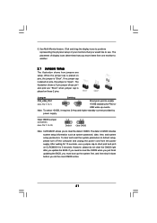
...Mixer" tool on your computer, you use. Please select "Mixer ToolBox" , click "Enable playback multi-streaming", and click "ok". HD 8CH I/O (ALiveNF6G-DVI / ALiveNF6G-VSTA) 1 Parallel Port 2 RJ-45 Port 3 Side Speaker (Gray) 4 Rear Speaker (Black) 5 Central / Bass (Orange) 6 Line In (Light... 8 Microphone (Pink) 9 USB 2.0 Ports (USB01) 10 USB 2.0 Ports (USB23) 11 VGA Port 12 PS/2 Keyboard Port (Purple) 13 PS/2 Mouse Port (Green) * If you need to connect a front panel audio cable to use front panel audio. 4 ASRock ALiveNF6G-DVI / ALiveNF6G-VSTA Motherboard English After restarting your...
...Mixer" tool on your computer, you use. Please select "Mixer ToolBox" , click "Enable playback multi-streaming", and click "ok". HD 8CH I/O (ALiveNF6G-DVI / ALiveNF6G-VSTA) 1 Parallel Port 2 RJ-45 Port 3 Side Speaker (Gray) 4 Rear Speaker (Black) 5 Central / Bass (Orange) 6 Line In (Light... 8 Microphone (Pink) 9 USB 2.0 Ports (USB01) 10 USB 2.0 Ports (USB23) 11 VGA Port 12 PS/2 Keyboard Port (Purple) 13 PS/2 Mouse Port (Green) * If you need to connect a front panel audio cable to use front panel audio. 4 ASRock ALiveNF6G-DVI / ALiveNF6G-VSTA Motherboard English After restarting your...
Quick Installation Guide
Page 7
...- 1 x HDMI_SPDIF header - Drivers, Utilities, AntiVirus Software (Trial Version) - Front panel audio connector - 3 x USB 2.0 headers (support 6 USB 2.0 ports) (see CAUTION 12) - SMBIOS 2.3.1 Support - ACPI 1.1 Compliance Wake Up Events - AMI Legal BIOS ...USB 2.0 Ports - 1 x RJ-45 Port - Supports jumperfree - Chassis Temperature Sensing - CPU Fan Tachometer - Microsoft® Windows® 2000/XP/XP Media Center/XP 64-bit/ VistaTM/VistaTM 64-bit compliant (see CAUTION 11) - 4Mb AMI BIOS - FCC, CE, Microsoft® WHQL Certificated English 7 ASRock ALiveNF6G-DVI / ALiveNF6G...
...- 1 x HDMI_SPDIF header - Drivers, Utilities, AntiVirus Software (Trial Version) - Front panel audio connector - 3 x USB 2.0 headers (support 6 USB 2.0 ports) (see CAUTION 12) - SMBIOS 2.3.1 Support - ACPI 1.1 Compliance Wake Up Events - AMI Legal BIOS ...USB 2.0 Ports - 1 x RJ-45 Port - Supports jumperfree - Chassis Temperature Sensing - CPU Fan Tachometer - Microsoft® Windows® 2000/XP/XP Media Center/XP 64-bit/ VistaTM/VistaTM 64-bit compliant (see CAUTION 11) - 4Mb AMI BIOS - FCC, CE, Microsoft® WHQL Certificated English 7 ASRock ALiveNF6G-DVI / ALiveNF6G...
Quick Installation Guide
Page 9
...channel, 6-channel, and 8-channel modes. You can also connect SATA hard disk to our website in the future. Please visit our website for USB 2.0 works fine under Microsoft® Windows® VistaTM 64-bit / VistaTM / XP 64-bit / XP SP1 or SP2 / 2000 SP4...you use external graphics card on page 23 to adjust your SATAII hard disk drive to Premium Discrete requirement at http://www.asrock.com English 9 ASRock ALiveNF6G-DVI / ALiveNF6G-VSTA Motherboard Power Management for Microsoft® Windows® VistaTM / VistaTM 64-bit driver and related information. 9. Please check...
...channel, 6-channel, and 8-channel modes. You can also connect SATA hard disk to our website in the future. Please visit our website for USB 2.0 works fine under Microsoft® Windows® VistaTM 64-bit / VistaTM / XP 64-bit / XP SP1 or SP2 / 2000 SP4...you use external graphics card on page 23 to adjust your SATAII hard disk drive to Premium Discrete requirement at http://www.asrock.com English 9 ASRock ALiveNF6G-DVI / ALiveNF6G-VSTA Motherboard Power Management for Microsoft® Windows® VistaTM / VistaTM 64-bit driver and related information. 9. Please check...
Quick Installation Guide
Page 17
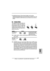
...After waiting for 15 seconds, use . If no jumper cap is placed on pins, the jumper is placed on CLRCMOS1 for PS/2 or USB wake up the system first, and then shut it requires 2 Amp and higher standby current provided by power supply. To clear and reset ..., please do the clear-CMOS action. The illustration shows a 3-pin jumper whose pin1 and pin2 are setup. The data in CMOS. English 17 ASRock ALiveNF6G-DVI / ALiveNF6G-VSTA Motherboard Click and drag the display icons to another. 2.6 Jumpers Setup The illustration shows how jumpers are "Short" when jumper cap is "Short". 6....
...After waiting for 15 seconds, use . If no jumper cap is placed on pins, the jumper is placed on CLRCMOS1 for PS/2 or USB wake up the system first, and then shut it requires 2 Amp and higher standby current provided by power supply. To clear and reset ..., please do the clear-CMOS action. The illustration shows a 3-pin jumper whose pin1 and pin2 are setup. The data in CMOS. English 17 ASRock ALiveNF6G-DVI / ALiveNF6G-VSTA Motherboard Click and drag the display icons to another. 2.6 Jumpers Setup The illustration shows how jumpers are "Short" when jumper cap is "Short". 6....
Quick Installation Guide
Page 19
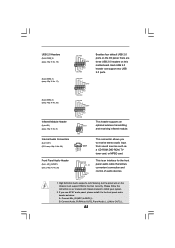
... function correctly. This connector allows you use AC'97 audio panel, please install it to receive stereo audio input from sound sources such as below: A. USB 2.0 Headers (9-pin USB8_9) (see p.2/p.3 No. 19) (9-pin USB6_7) (see p.2/p.3, No. 26) This header supports an optional wireless transmitting and receiving infrared module. High Definition Audio.... Connect Audio_R (RIN) to OUT2_R and Audio_L (LIN) to install your system. 2. Please follow the instruction in our manual and chassis manual to OUT2_L. 19 ASRock ALiveNF6G-DVI / ALiveNF6G-VSTA Motherboard English B.
... function correctly. This connector allows you use AC'97 audio panel, please install it to receive stereo audio input from sound sources such as below: A. USB 2.0 Headers (9-pin USB8_9) (see p.2/p.3 No. 19) (9-pin USB6_7) (see p.2/p.3, No. 26) This header supports an optional wireless transmitting and receiving infrared module. High Definition Audio.... Connect Audio_R (RIN) to OUT2_R and Audio_L (LIN) to install your system. 2. Please follow the instruction in our manual and chassis manual to OUT2_L. 19 ASRock ALiveNF6G-DVI / ALiveNF6G-VSTA Motherboard English B.


