
RAID Installation Guide
Page 2
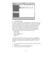
... RAID 0 function can start to use NVIDIA RAID Utility to use RAID 0, RAID 1, RAID 0+1, JBOD, or RAID 5 function with your motherboard is an instruction for creating RAID arrays. SATAII_3 (port 2.0) --> Means controller 2 's first port. NVIDIA BIOS RAID Installation Guide NVIDIA BIOS RAID... Installation Guide is equipped with NVIDIA utility naming. If your motherboard. It will improve data access and storage since it does not provide any HDDs of the RAID 0 Disk will double the data ...
... RAID 0 function can start to use NVIDIA RAID Utility to use RAID 0, RAID 1, RAID 0+1, JBOD, or RAID 5 function with your motherboard is an instruction for creating RAID arrays. SATAII_3 (port 2.0) --> Means controller 2 's first port. NVIDIA BIOS RAID Installation Guide NVIDIA BIOS RAID... Installation Guide is equipped with NVIDIA utility naming. If your motherboard. It will improve data access and storage since it does not provide any HDDs of the RAID 0 Disk will double the data ...
RAID Installation Guide
Page 9
...with two SATA / SATAII ports, you may choose to use RAID 0, RAID 1, RAID 0+1, JBOD, or RAID 5 function with your motherboard provides in advance and follow the instruction in this section are RAID enabled. Please refer to the SATA / SATAII HDDs amount you may... arrays. The RAID items which may choose to use RAID 0, RAID 1, or JBOD function with your motherboard according to the RAID functions your motherboard. RAID 0: Striping - RAID 0+1: Stripe Mirroring - C. If your motherboard is equipped with four SATA / SATAII ports, you install. If you plan to use NVRAIDMAN to create...
...with two SATA / SATAII ports, you may choose to use RAID 0, RAID 1, RAID 0+1, JBOD, or RAID 5 function with your motherboard provides in advance and follow the instruction in this section are RAID enabled. Please refer to the SATA / SATAII HDDs amount you may... arrays. The RAID items which may choose to use RAID 0, RAID 1, or JBOD function with your motherboard according to the RAID functions your motherboard. RAID 0: Striping - RAID 0+1: Stripe Mirroring - C. If your motherboard is equipped with four SATA / SATAII ports, you install. If you plan to use NVRAIDMAN to create...
User Manual
Page 2
...in this manual. This device complies with Part 15 of the FCC Rules. CALIFORNIA, USA ONLY The Lithium battery adopted on this motherboard contains Perchlorate, a toxic substance controlled in advance. When you discard the Lithium battery in California, USA, please follow the related...regulations in Perchlorate Best Management Practices (BMP) regulations passed by the California Legislature. With respect to the contents of this manual, ASRock does not provide warranty of any means, except duplication of documentation by the purchaser for backup purpose, without intent to infringe. ...
...in this manual. This device complies with Part 15 of the FCC Rules. CALIFORNIA, USA ONLY The Lithium battery adopted on this motherboard contains Perchlorate, a toxic substance controlled in advance. When you discard the Lithium battery in California, USA, please follow the related...regulations in Perchlorate Best Management Practices (BMP) regulations passed by the California Legislature. With respect to the contents of this manual, ASRock does not provide warranty of any means, except duplication of documentation by the purchaser for backup purpose, without intent to infringe. ...

User Manual
Page 3
... Serial ATA (SATA) / Serial ATAII (SATAII) Hard Disks Installation 28 2.12 Hot Plug and Hot Swap Functions for Windows® VistaTM Premium and Basic Logo 9 1.4 Motherboard Layout (ALiveNF6G-DVI 10 1.5 Motherboard Layout (ALiveNF6G-VSTA 11 1.6 HD 8CH I/O (ALiveNF6G-DVI / ALiveNF6G-VSTA 12 2 . Contents 1 .
... Serial ATA (SATA) / Serial ATAII (SATAII) Hard Disks Installation 28 2.12 Hot Plug and Hot Swap Functions for Windows® VistaTM Premium and Basic Logo 9 1.4 Motherboard Layout (ALiveNF6G-DVI 10 1.5 Motherboard Layout (ALiveNF6G-VSTA 11 1.6 HD 8CH I/O (ALiveNF6G-DVI / ALiveNF6G-VSTA 12 2 . Contents 1 .
User Manual
Page 5
... as well. In case any modifications of the motherboard and step-bystep guide to change without further notice. 1. ASRock website http://www.asrock.com 1.1 Package Contents 1 x ASRock ALiveNF6G-DVI / ALiveNF6G-VSTA Motherboard (Micro ATX Form Factor: 9.6-in x 9.6-in, 24.4 cm x 24.4 cm) 1 x ASRock ALiveNF6G-DVI / ALiveNF6G-VSTA Quick Installation Guide 1 x ASRock ALiveNF6G-DVI / ALiveNF6G-VSTA Support CD 1 x Ultra ATA 66/100/133 IDE Ribbon Cable (80...
... as well. In case any modifications of the motherboard and step-bystep guide to change without further notice. 1. ASRock website http://www.asrock.com 1.1 Package Contents 1 x ASRock ALiveNF6G-DVI / ALiveNF6G-VSTA Motherboard (Micro ATX Form Factor: 9.6-in x 9.6-in, 24.4 cm x 24.4 cm) 1 x ASRock ALiveNF6G-DVI / ALiveNF6G-VSTA Quick Installation Guide 1 x ASRock ALiveNF6G-DVI / ALiveNF6G-VSTA Support CD 1 x Ultra ATA 66/100/133 IDE Ribbon Cable (80...
User Manual
Page 8
... for possible damage caused by overclocking. WARNING Please realize that there is detected, the system will automatically shutdown. This motherboard supports Dual Channel Memory Technology. For Windows® XP 64-bit and Windows® VistaTM 64bit with overclocking, including... improve heat dissipation, remember to read "Untied Overclocking Technology" on the motherboard functions properly and unplug the power cord, then plug it is no such limitation. 6. This motherboard supports ASRock AM2 Boost overclocking technology. Overclocking may cause the instability of memory modules ...
... for possible damage caused by overclocking. WARNING Please realize that there is detected, the system will automatically shutdown. This motherboard supports Dual Channel Memory Technology. For Windows® XP 64-bit and Windows® VistaTM 64bit with overclocking, including... improve heat dissipation, remember to read "Untied Overclocking Technology" on the motherboard functions properly and unplug the power cord, then plug it is no such limitation. 6. This motherboard supports ASRock AM2 Boost overclocking technology. Overclocking may cause the instability of memory modules ...
User Manual
Page 9
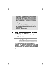
...SP1 or SP2 / 2000 SP4. 12. Please check the table on this motherboard supports both stereo and mono modes. You can also connect SATA hard disk to our website in the future. ASRock website http://www.asrock.com 1.3 Minimum Hardware Requirement Table for proper connection. 10. CPU Memory Sempron...Windows® VistaTM Basic logo, please adjust the shared memory size of onboard VGA to Premium Discrete requirement at http://www.asrock.com 9 For microphone input, this motherboard, please refer to 128MB or above. * If you use external graphics card on page 12 for Windows® VistaTM...
...SP1 or SP2 / 2000 SP4. 12. Please check the table on this motherboard supports both stereo and mono modes. You can also connect SATA hard disk to our website in the future. ASRock website http://www.asrock.com 1.3 Minimum Hardware Requirement Table for proper connection. 10. CPU Memory Sempron...Windows® VistaTM Basic logo, please adjust the shared memory size of onboard VGA to Premium Discrete requirement at http://www.asrock.com 9 For microphone input, this motherboard, please refer to 128MB or above. * If you use external graphics card on page 12 for Windows® VistaTM...
User Manual
Page 10
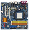
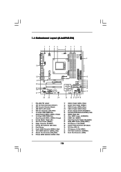
...CD1 (Black) 30 PCI Slots (PCI1- 2) 31 PCI Express x16 Slot (PCIE1) 32 ATX Power Connector (ATXPWR1) 33 Serial Port Connector (COM1) 10 1.4 Motherboard Layout (ALiveNF6G-DVI) 1 2 34 5 67 8 24.4cm (9.6-in) PS2 Keyboard PS2 Mouse 1 PS2_USB_PW1 ATX12V1 CPU_FAN1 IR1 1 9 Super I/O GAME1 1 Dual Core CPU Dual... 27 Top: LINE IN Center: FRONT Bottom: MIC IN LAN PHY CD1 AUDIO CODEC HDMI_SPDIF1 1 1 HD_AUDIO1 ` PCIE1 PCI EXPRESS RAID ALiveNF6G-DVI PCI1 PCI2 PCIE2 7.1CH HD HDMR1 CMOS BATTERY CLRCMOS1 1 NVIDIA GeForce 6100 / nForce 430 or GeForce 6150SE / nForce 430 Chipset RoHS...
...CD1 (Black) 30 PCI Slots (PCI1- 2) 31 PCI Express x16 Slot (PCIE1) 32 ATX Power Connector (ATXPWR1) 33 Serial Port Connector (COM1) 10 1.4 Motherboard Layout (ALiveNF6G-DVI) 1 2 34 5 67 8 24.4cm (9.6-in) PS2 Keyboard PS2 Mouse 1 PS2_USB_PW1 ATX12V1 CPU_FAN1 IR1 1 9 Super I/O GAME1 1 Dual Core CPU Dual... 27 Top: LINE IN Center: FRONT Bottom: MIC IN LAN PHY CD1 AUDIO CODEC HDMI_SPDIF1 1 1 HD_AUDIO1 ` PCIE1 PCI EXPRESS RAID ALiveNF6G-DVI PCI1 PCI2 PCIE2 7.1CH HD HDMR1 CMOS BATTERY CLRCMOS1 1 NVIDIA GeForce 6100 / nForce 430 or GeForce 6150SE / nForce 430 Chipset RoHS...

User Manual
Page 11
...Red) 32 ATX Power Connector (ATXPWR1) 15 Chassis Fan Connector (CHA_FAN1) 33 Serial Port Connector (COM1) 16 Primary SATAII Connector (SATAII_1, Red) 11 1.5 Motherboard Layout (ALiveNF6G-VSTA) 1 2 34 5 67 8 24.4cm (9.6-in) PS2 Keyboard PS2 Mouse 1 PS2_USB_PW1 ATX12V1 CPU_FAN1 IR1 1 9 Super I/O GAME1 1 Dual Core...27 Top: LINE IN Center: FRONT Bottom: MIC IN LAN PHY CD1 AUDIO CODEC HDMI_SPDIF1 1 1 HD_AUDIO1 ` PCIE1 PCI EXPRESS RAID ALiveNF6G-VSTA PCI1 PCI2 PCIE2 7.1CH HD HDMR1 CMOS BATTERY CLRCMOS1 1 NVIDIA GeForce 6100 / nForce 430 or GeForce 6150SE / nForce 430 ...
...Red) 32 ATX Power Connector (ATXPWR1) 15 Chassis Fan Connector (CHA_FAN1) 33 Serial Port Connector (COM1) 16 Primary SATAII Connector (SATAII_1, Red) 11 1.5 Motherboard Layout (ALiveNF6G-VSTA) 1 2 34 5 67 8 24.4cm (9.6-in) PS2 Keyboard PS2 Mouse 1 PS2_USB_PW1 ATX12V1 CPU_FAN1 IR1 1 9 Super I/O GAME1 1 Dual Core...27 Top: LINE IN Center: FRONT Bottom: MIC IN LAN PHY CD1 AUDIO CODEC HDMI_SPDIF1 1 1 HD_AUDIO1 ` PCIE1 PCI EXPRESS RAID ALiveNF6G-VSTA PCI1 PCI2 PCIE2 7.1CH HD HDMR1 CMOS BATTERY CLRCMOS1 1 NVIDIA GeForce 6100 / nForce 430 or GeForce 6150SE / nForce 430 ...
User Manual
Page 13
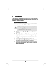
... that the power is switched off or the power cord is a Micro ATX form factor (9.6-in x 9.6-in, 24.4 cm x 24.4 cm) motherboard. Doing so may cause severe damage to static electricity, NEVER place your chassis to use a grounded wrist strap or touch a safety grounded object before...component. 2. 2. Failure to do not touch the ICs. 4. Unplug the power cord from the power supply. To avoid damaging the motherboard components due to the motherboard, peripherals, and/or components. 1. When placing screws into it on the carpet or the like. Installation This is detached from the wall...
... that the power is switched off or the power cord is a Micro ATX form factor (9.6-in x 9.6-in, 24.4 cm x 24.4 cm) motherboard. Doing so may cause severe damage to static electricity, NEVER place your chassis to use a grounded wrist strap or touch a safety grounded object before...component. 2. 2. Failure to do not touch the ICs. 4. Unplug the power cord from the power supply. To avoid damaging the motherboard components due to the motherboard, peripherals, and/or components. 1. When placing screws into it on the carpet or the like. Installation This is detached from the wall...
User Manual
Page 14
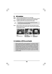
... between the CPU and the heatsink to the CPU FAN connector (CPU_FAN1, see Page 10 / 11, No. 5). Step 2. DO NOT force the CPU into this motherboard, it fits in place, press it firmly on the socket while you install the CPU into the socket to indicate that it is in place...
... between the CPU and the heatsink to the CPU FAN connector (CPU_FAN1, see Page 10 / 11, No. 5). Step 2. DO NOT force the CPU into this motherboard, it fits in place, press it firmly on the socket while you install the CPU into the socket to indicate that it is in place...
User Manual
Page 15
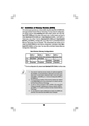
... install two memory modules, for optimal compatibility and reliability, it is not allowed to install a DDR memory module into DDRII slot; otherwise, this motherboard, it is unable to install them either in the set of the same color. In other words, install them in all four slots. You ... DDRII_2), or in Dual Channel A (DDRII_1 and DDRII_2; see p.10/p.11 No.7), so that Dual Channel Memory Technology can be damaged. 15 This motherboard also allows you always need to install identical (the same brand, speed, size and chiptype) DDRII DIMM pair in the DDRII DIMM slots on this...
... install two memory modules, for optimal compatibility and reliability, it is not allowed to install a DDR memory module into DDRII slot; otherwise, this motherboard, it is unable to install them either in the set of the same color. In other words, install them in all four slots. You ... DDRII_2), or in Dual Channel A (DDRII_1 and DDRII_2; see p.10/p.11 No.7), so that Dual Channel Memory Technology can be damaged. 15 This motherboard also allows you always need to install identical (the same brand, speed, size and chiptype) DDRII DIMM pair in the DDRII DIMM slots on this...
User Manual
Page 16
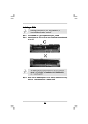
Installing a DIMM Please make sure to the motherboard and the DIMM if you force the DIMM into the slot until the retaining clips at incorrect orientation. Unlock a DIMM slot by pressing the retaining ...
Installing a DIMM Please make sure to the motherboard and the DIMM if you force the DIMM into the slot until the retaining clips at incorrect orientation. Unlock a DIMM slot by pressing the retaining ...

User Manual
Page 17
...2. The HDMR slot is used to PCIE1 (PCIE x16 slot) on ALiveNF6G-DVI motherboard. Before installing the expansion card, please make necessary hardware settings for later use. Step 3. Align the card connector with x16 lane width graphics cards or ASRock DVI Graphics-SI card (ALiveNF6GDVI). Installing an expansion card Step 1. Step .... Fasten the card to use . HDMR slot: HDMR slot is unplugged. You can only choose either PCI Express VGA card or DVI Graphics-SI card to install to insert a HDMR card (optional) with PCIE2 slot; Remove the bracket facing the slot that have ...
...2. The HDMR slot is used to PCIE1 (PCIE x16 slot) on ALiveNF6G-DVI motherboard. Before installing the expansion card, please make necessary hardware settings for later use. Step 3. Align the card connector with x16 lane width graphics cards or ASRock DVI Graphics-SI card (ALiveNF6GDVI). Installing an expansion card Step 1. Step .... Fasten the card to use . HDMR slot: HDMR slot is unplugged. You can only choose either PCI Express VGA card or DVI Graphics-SI card to install to insert a HDMR card (optional) with PCIE2 slot; Remove the bracket facing the slot that have ...
User Manual
Page 18
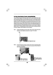
... (ALiveNF6G-DVI) This motherboard supports Dual Monitor feature. To enjoy Dual Monitor feature, please refer to the below procedures for proper installation of DVI Graphics-SI card which is inserted to the DVI-D output connector of DVI Graphics-SI card in advance. Connect the DVI-D connector of DVI-D ...input monitor to PCIE1 (PCIE x16 slot) on this motherboard. Step 1. DVI Graphics-SI card Step 2....
... (ALiveNF6G-DVI) This motherboard supports Dual Monitor feature. To enjoy Dual Monitor feature, please refer to the below procedures for proper installation of DVI Graphics-SI card which is inserted to the DVI-D output connector of DVI Graphics-SI card in advance. Connect the DVI-D connector of DVI-D ...input monitor to PCIE1 (PCIE x16 slot) on this motherboard. Step 1. DVI Graphics-SI card Step 2....
User Manual
Page 19
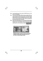
... Settings" icon on on the desktop to use DVI-D output function with this motherboard. You are allowed to choose same or different display contents shown on the I/O panel of DVI-D output function with this motherboard. Independent display controllers for DVI-D and D-Sub ports to support dual VGA output: DVI-D and D-sub ports can start to your...
... Settings" icon on on the desktop to use DVI-D output function with this motherboard. You are allowed to choose same or different display contents shown on the I/O panel of DVI-D output function with this motherboard. Independent display controllers for DVI-D and D-Sub ports to support dual VGA output: DVI-D and D-sub ports can start to your...

User Manual
Page 20
...-click the display icon and select "Attached", if necessary. Please refer to the following steps to this motherboard. Please refer to apply these new values. Connect the DVI-D input monitor cable to the steps below. (The item names and operation procedures described in the Display ... feature. Press to PCIE1 (PCIE x16 slot). Right-click the display icon in this monitor". F. 2.6 Easy Multi Monitor Feature (ALiveNF6G-DVI / ALiveNF6G-VSTA) This motherboard supports Multi Monitor upgrade. Connect the D-Sub input monitor cable to the VGA/D-Sub port on PCI Express VGA card, you wish ...
...-click the display icon and select "Attached", if necessary. Please refer to the following steps to this motherboard. Please refer to apply these new values. Connect the DVI-D input monitor cable to the steps below. (The item names and operation procedures described in the Display ... feature. Press to PCIE1 (PCIE x16 slot). Right-click the display icon in this monitor". F. 2.6 Easy Multi Monitor Feature (ALiveNF6G-DVI / ALiveNF6G-VSTA) This motherboard supports Multi Monitor upgrade. Connect the D-Sub input monitor cable to the VGA/D-Sub port on PCI Express VGA card, you wish ...
User Manual
Page 22
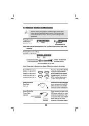
... connector connect to the power supply Please connect the black end of the SATA data cable can be connected to the power connector on the motherboard. 2.8 Onboard Headers and Connectors Onboard headers and connectors are NOT jumpers. Serial ATA (SATA) Data Cable (Optional) Either end of SATA ... support SATAII or SATA hard disk for the details. Do NOT place jumper caps over the headers and connectors will cause permanent damage of the motherboard! • Floppy Connector (33-pin FLOPPY1) (see p.10/p.11 No. 10) Pin1 FLOPPY1 the red-striped side to the instruction of ...
... connector connect to the power supply Please connect the black end of the SATA data cable can be connected to the power connector on the motherboard. 2.8 Onboard Headers and Connectors Onboard headers and connectors are NOT jumpers. Serial ATA (SATA) Data Cable (Optional) Either end of SATA ... support SATAII or SATA hard disk for the details. Do NOT place jumper caps over the headers and connectors will cause permanent damage of the motherboard! • Floppy Connector (33-pin FLOPPY1) (see p.10/p.11 No. 10) Pin1 FLOPPY1 the red-striped side to the instruction of ...
User Manual
Page 23
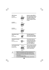
... audio header as a CD-ROM, DVD-ROM, TV tuner card, or MPEG card. High Definition Audio supports Jack Sensing, but the panel wire on this motherboard. Connect Mic_IN (MIC) to function correctly. USB 2.0 Headers (9-pin USB8_9) (see p.10/p.11 No. 19) USB_PWR P-9 P+9 GND DUMMY 1 GND P+8 P-8 USB_PWR Besides four default USB 2.0 ports...
... audio header as a CD-ROM, DVD-ROM, TV tuner card, or MPEG card. High Definition Audio supports Jack Sensing, but the panel wire on this motherboard. Connect Mic_IN (MIC) to function correctly. USB 2.0 Headers (9-pin USB8_9) (see p.10/p.11 No. 19) USB_PWR P-9 P+9 GND DUMMY 1 GND P+8 P-8 USB_PWR Besides four default USB 2.0 ports...
User Manual
Page 24
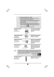
... Please connect the CPU fan cable to Pin 1-3. C. Enter BIOS Setup Utility. Enter Windows system. Please connect a chassis fan cable to this motherboard, please connect it to this motherboard provides 4-Pin CPU fan (Quiet Fan) support, the 3-Pin CPU fan still can work successfully even without the fan speed control function. Enter...
... Please connect the CPU fan cable to Pin 1-3. C. Enter BIOS Setup Utility. Enter Windows system. Please connect a chassis fan cable to this motherboard, please connect it to this motherboard provides 4-Pin CPU fan (Quiet Fan) support, the 3-Pin CPU fan still can work successfully even without the fan speed control function. Enter...

