
RAID Installation Guide
Page 8
... to the OS you can create, delete, or rebuild any RAID array. Enter NVRAIDMAN RAID driver is also a "Mediashield" shortcut on the desktop.) Then, the below to configure RAID functions by using NVIDIAMAN under Windows environment. NVIDIA Windows RAID Installation Guide NVIDIA Windows RAID Installation Guide is an instruction for Windows 2000 / XP / XP 64-bit Users A. Please enter NVRAIDMAN by clicking on Start → Programs → NVIDIA Corporation → Mediashield → Mediashield...
... to the OS you can create, delete, or rebuild any RAID array. Enter NVRAIDMAN RAID driver is also a "Mediashield" shortcut on the desktop.) Then, the below to configure RAID functions by using NVIDIAMAN under Windows environment. NVIDIA Windows RAID Installation Guide NVIDIA Windows RAID Installation Guide is an instruction for Windows 2000 / XP / XP 64-bit Users A. Please enter NVRAIDMAN by clicking on Start → Programs → NVIDIA Corporation → Mediashield → Mediashield...
User Manual
Page 9
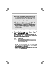
... hard disk to SATAII connector, please read the "SATAII Hard Disk Setup Guide" on this motherboard supports 2-channel, 4-channel, 6-channel, and 8-channel modes. You can also connect SATA hard disk to SATAII mode. As long as we have the latest driver, we will update it to 128MB or above 512MB and plan to submit Windows® VistaTM Premium or Basic logo, please adjust the shared memory size of onboard VGA to 64MB. 9. If you use onboard VGA with total system memory size...
... hard disk to SATAII connector, please read the "SATAII Hard Disk Setup Guide" on this motherboard supports 2-channel, 4-channel, 6-channel, and 8-channel modes. You can also connect SATA hard disk to SATAII mode. As long as we have the latest driver, we will update it to 128MB or above 512MB and plan to submit Windows® VistaTM Premium or Basic logo, please adjust the shared memory size of onboard VGA to 64MB. 9. If you use onboard VGA with total system memory size...
User Manual
Page 10
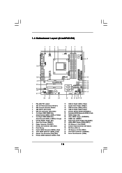
... Clear CMOS Jumper (CLRCMOS1) 25 HDMR Slot (HDMR1) 26 Front Panel Audio Header (HD_AUDIO1) 27 HDMI_SPDIF Header (HDMI_SPDIF1) 28 PCI Express x1 Slot (PCIE2) 29 Internal Audio Connector: CD1 (Black) 30 PCI Slots (PCI1- 2) 31 PCI Express x16 Slot (PCIE1) 32 ATX Power Connector (ATXPWR1) 33 Serial Port Connector (COM1) 10 1.4 Motherboard Layout (ALiveNF6G-DVI) 1 2 34 5 67 8 24.4cm (9.6-in) PS2 Keyboard PS2 Mouse 1 PS2_USB_PW1 ATX12V1 CPU_FAN1 IR1 1 9 Super I/O GAME1 1 Dual Core CPU Dual Channel PARALLEL PORT DDRII_3 (64/72 bit, 240F-pSinBm8o0d0ule) DDRII_4 (64/72 bit, 240-pin...
... Clear CMOS Jumper (CLRCMOS1) 25 HDMR Slot (HDMR1) 26 Front Panel Audio Header (HD_AUDIO1) 27 HDMI_SPDIF Header (HDMI_SPDIF1) 28 PCI Express x1 Slot (PCIE2) 29 Internal Audio Connector: CD1 (Black) 30 PCI Slots (PCI1- 2) 31 PCI Express x16 Slot (PCIE1) 32 ATX Power Connector (ATXPWR1) 33 Serial Port Connector (COM1) 10 1.4 Motherboard Layout (ALiveNF6G-DVI) 1 2 34 5 67 8 24.4cm (9.6-in) PS2 Keyboard PS2 Mouse 1 PS2_USB_PW1 ATX12V1 CPU_FAN1 IR1 1 9 Super I/O GAME1 1 Dual Core CPU Dual Channel PARALLEL PORT DDRII_3 (64/72 bit, 240F-pSinBm8o0d0ule) DDRII_4 (64/72 bit, 240-pin...

User Manual
Page 11
... 4 AM2 940-Pin CPU Socket 20 USB 2.0 Header (USB4_5, Blue) 5 CPU Fan Connector (CPU_FAN1) 21 Chassis Speaker Header (SPEAKER 1) 6 2 x 240-pin DDRII DIMM Slots 22 Secondary SATAII Connector (SATAII_2,Red) (Dual Channel A: DDRII_1, DDRII_2; Orange) 25 HDMR Slot (HDMR1) 8 Infrared Module Header (IR1) 26 Front Panel Audio Header (HD_AUDIO1) 9 Game Port Header (GAME1) 27 HDMI_SPDIF Header (HDMI_SPDIF1) 10 Floppy Connector (FLOPPY1) 28 PCI Express x1 Slot (PCIE2) 11 Primary IDE Connector (IDE1, Blue) 29 Internal Audio Connector: CD1 (Black) 12 Flash Memory 30 PCI Slots (PCI1- 2) 13...
... 4 AM2 940-Pin CPU Socket 20 USB 2.0 Header (USB4_5, Blue) 5 CPU Fan Connector (CPU_FAN1) 21 Chassis Speaker Header (SPEAKER 1) 6 2 x 240-pin DDRII DIMM Slots 22 Secondary SATAII Connector (SATAII_2,Red) (Dual Channel A: DDRII_1, DDRII_2; Orange) 25 HDMR Slot (HDMR1) 8 Infrared Module Header (IR1) 26 Front Panel Audio Header (HD_AUDIO1) 9 Game Port Header (GAME1) 27 HDMI_SPDIF Header (HDMI_SPDIF1) 10 Floppy Connector (FLOPPY1) 28 PCI Express x1 Slot (PCIE2) 11 Primary IDE Connector (IDE1, Blue) 29 Internal Audio Connector: CD1 (Black) 12 Flash Memory 30 PCI Slots (PCI1- 2) 13...
User Manual
Page 26
... to HDMI device, such as a digital television (DTV). Please refer to the user manual of HDMI_SPDIF cable to the VGA card user manual for detailed connection procedures. 2.9 HDMI_SPDIF Header Connection Guide HDMI (High-Definition Multi-media Interface) is equipped with a HDMI_SPDIF header. A complete HDMI system requires a HDMI VGA card and a HDMI ready motherboard with a HDMI_SPDIF header, which provides an interface between any compatible digital audio/video source, such as a set-top box, DVD player, A/V receiver and a compatible digital audio or video monitor...
... to HDMI device, such as a digital television (DTV). Please refer to the user manual of HDMI_SPDIF cable to the VGA card user manual for detailed connection procedures. 2.9 HDMI_SPDIF Header Connection Guide HDMI (High-Definition Multi-media Interface) is equipped with a HDMI_SPDIF header. A complete HDMI system requires a HDMI VGA card and a HDMI ready motherboard with a HDMI_SPDIF header, which provides an interface between any compatible digital audio/video source, such as a set-top box, DVD player, A/V receiver and a compatible digital audio or video monitor...

User Manual
Page 28
... install SATA / SATAII hard disks on the support CD driver page. If SATA / SATAII HDDs are NOT set for RAID configuration, it is called "Hot Swap" for the action to insert and remove the SATA / SATAII HDDs while the system is still power-on and in working condition. Therefore, the drivers you to install those required drivers. This section will guide you install can be auto-detected and listed on this motherboard for internal storage devices. STEP 1: Install...
... install SATA / SATAII hard disks on the support CD driver page. If SATA / SATAII HDDs are NOT set for RAID configuration, it is called "Hot Swap" for the action to insert and remove the SATA / SATAII HDDs while the system is still power-on and in working condition. Therefore, the drivers you to install those required drivers. This section will guide you install can be auto-detected and listed on this motherboard for internal storage devices. STEP 1: Install...
User Manual
Page 30
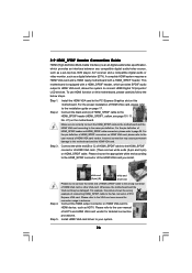
... screen, "Generate Serial ATA driver diskette [YN]?", press . STEP 3: Use "RAID Installation Guide" to install Windows® 2000 / Windows® XP / Windows® XP 64-bit OS on SATA / SATAII HDDs, you will see the message on your system. After step1, 2, 3, you can start to configure RAID function, you see these messages, Please insert a blank formatted diskette into floppy drive A: press any key to [RAID] in the Support CD: .. \ RAID Installation Guide STEP 4: Install Windows® 2000 / Windows...
... screen, "Generate Serial ATA driver diskette [YN]?", press . STEP 3: Use "RAID Installation Guide" to install Windows® 2000 / Windows® XP / Windows® XP 64-bit OS on SATA / SATAII HDDs, you will see the message on your system. After step1, 2, 3, you can start to configure RAID function, you see these messages, Please insert a blank formatted diskette into floppy drive A: press any key to [RAID] in the Support CD: .. \ RAID Installation Guide STEP 4: Install Windows® 2000 / Windows...
User Manual
Page 31
... you start to configure RAID function, you enable Untied Overclocking function, please enter "Overclock Mode" option of BIOS setup to the BIOS RAID installation guide part of the document in the following path in the fixed mode so that , please insert Windows® VistaTM / Windows® VistaTM 64-bit optical disk into the optical drive again to continue the installation. Please refer to set RAID configuration. page, please insert the ASRock Support CD into the optical drive to fixed PCI / PCIE...
... you start to configure RAID function, you enable Untied Overclocking function, please enter "Overclock Mode" option of BIOS setup to the BIOS RAID installation guide part of the document in the following path in the fixed mode so that , please insert Windows® VistaTM / Windows® VistaTM 64-bit optical disk into the optical drive again to continue the installation. Please refer to set RAID configuration. page, please insert the ASRock Support CD into the optical drive to fixed PCI / PCIE...
User Manual
Page 36
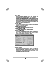
... Configuration optiona: [Enabled], [Disabled]. If Manual, multiplier and voltage will display Processor Maximum Voltage for reference. otherwise, it is set to system stability or compatibility issue with some memory modules or power supplies. BIOS SETUP UTILITY Advanced CPU Configuration AM2 Boost Overclock Mode CPU Frequency (MHz) PCIE Frequency (MHz) Boot Failure Guard CPU/LDT Spread Spectrum PCIE Spread Spectrum SATA Spread Spectrum Cool' n' Quiet Dual Core Support [Disabled] [Auto] [200] [100] [Enabled] [0.75% Hershey] [Enabled] [Enabled] [Auto] [Enabled] Processor...
... Configuration optiona: [Enabled], [Disabled]. If Manual, multiplier and voltage will display Processor Maximum Voltage for reference. otherwise, it is set to system stability or compatibility issue with some memory modules or power supplies. BIOS SETUP UTILITY Advanced CPU Configuration AM2 Boost Overclock Mode CPU Frequency (MHz) PCIE Frequency (MHz) Boot Failure Guard CPU/LDT Spread Spectrum PCIE Spread Spectrum SATA Spread Spectrum Cool' n' Quiet Dual Core Support [Disabled] [Auto] [200] [100] [Enabled] [0.75% Hershey] [Enabled] [Enabled] [Auto] [Enabled] Processor...
User Manual
Page 40
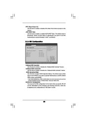
... SATA Controller Use this motherboard to submit Windows® VistaTM certification. 3.3.4 IDE Configuration Advanced BIOS SETUP UTILITY IDE Configuration OnBoard IDE Controller OnBoard SATA Controller SATA Operation Mode IDE Master IDE Slave SATAII 1 SATAII 2 SATAII 3 SATAII 4 [Enabled] [Enabled] [non-RAID] [Hard Disk] [Not Detected] [Not Detected] [Not Detected] [Not Detected] [Not Detected] ENABLED: enables the integrated IDE Controller. The default value is [non-RAID]. SATA Operation Mode Use this item to enable or disable RTC (Real Time Clock) to power on SATA / SATAII HDDs...
... SATA Controller Use this motherboard to submit Windows® VistaTM certification. 3.3.4 IDE Configuration Advanced BIOS SETUP UTILITY IDE Configuration OnBoard IDE Controller OnBoard SATA Controller SATA Operation Mode IDE Master IDE Slave SATAII 1 SATAII 2 SATAII 3 SATAII 4 [Enabled] [Enabled] [non-RAID] [Hard Disk] [Not Detected] [Not Detected] [Not Detected] [Not Detected] [Not Detected] ENABLED: enables the integrated IDE Controller. The default value is [non-RAID]. SATA Operation Mode Use this item to enable or disable RTC (Real Time Clock) to power on SATA / SATAII HDDs...
User Manual
Page 42
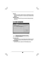
... Select Screen Select Item Change Option General Help Load Defaults Save and Exit Exit v02.54 (C) Copyright 1985-2003, American Megatrends, Inc. PCI Latency Timer The default value is recommended to malfunction. Setting wrong values in units of PCI clocks for PCI device latency timer register. S.M.A.R.T. PCI IDE BusMaster Use this item to enable 32-bit access to maximize the IDE hard disk data transfer rate. 3.3.5 PCIPnP Configuration BIOS SETUP UTILITY Advanced Advanced PCI / PnP Settings WARNING: Setting...
... Select Screen Select Item Change Option General Help Load Defaults Save and Exit Exit v02.54 (C) Copyright 1985-2003, American Megatrends, Inc. PCI Latency Timer The default value is recommended to malfunction. Setting wrong values in units of PCI clocks for PCI device latency timer register. S.M.A.R.T. PCI IDE BusMaster Use this item to enable 32-bit access to maximize the IDE hard disk data transfer rate. 3.3.5 PCIPnP Configuration BIOS SETUP UTILITY Advanced Advanced PCI / PnP Settings WARNING: Setting...
User Manual
Page 49
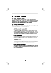
... necessary drivers to activate the devices. 4.2.3 Utilities Menu The Utilities Menu shows the applications software that enhance the motherboard features. 4.2.1 Running The Support CD To begin using the support CD, insert the CD into your dealer for general reference only. Software Support 4.1 Install Operating System This motherboard supports various Microsoft® Windows® operating systems: 2000 / XP / XP 64-bit / VistaTM / VistaTM 64-bit. Because motherboard settings and hardware options vary, use the setup...
... necessary drivers to activate the devices. 4.2.3 Utilities Menu The Utilities Menu shows the applications software that enhance the motherboard features. 4.2.1 Running The Support CD To begin using the support CD, insert the CD into your dealer for general reference only. Software Support 4.1 Install Operating System This motherboard supports various Microsoft® Windows® operating systems: 2000 / XP / XP 64-bit / VistaTM / VistaTM 64-bit. Because motherboard settings and hardware options vary, use the setup...

User Manual
Page 50
... sure to install "AMD Processor Driver" from the "Support CD" first. Double-click the Display icon in the Control Panel then select the Screen Saver tab. 4. From the Power schemes combo list box, select Minimal Power Management. 6. The following dialog box appears. 5. Click OK to enable AMD's Cool 'n' QuietTM technology under Windows® system. From the Windows® 2000/XP operating system, click the Start button. When using Windows® 2000...
... sure to install "AMD Processor Driver" from the "Support CD" first. Double-click the Display icon in the Control Panel then select the Screen Saver tab. 4. From the Power schemes combo list box, select Minimal Power Management. 6. The following dialog box appears. 5. Click OK to enable AMD's Cool 'n' QuietTM technology under Windows® system. From the Windows® 2000/XP operating system, click the Start button. When using Windows® 2000...
Quick Installation Guide
Page 9
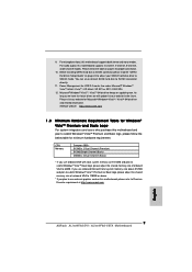
... for proper connection. 10. CPU Memory Sempron 2800+ 512MB x 2 Dual Channel (Premium) 512MB Single Channel (Basic) 256MB x 2 Dual Channel (Basic) * If you plan to use onboard VGA with total system memory size 512MB and plan to submit Windows® VistaTM Basic logo, please adjust the shared memory size of onboard VGA to SATAII connector, please read the "SATAII Hard Disk Setup Guide" on updating now. 9. For microphone input, this motherboard, please refer to SATAII mode. Power Management...
... for proper connection. 10. CPU Memory Sempron 2800+ 512MB x 2 Dual Channel (Premium) 512MB Single Channel (Basic) 256MB x 2 Dual Channel (Basic) * If you plan to use onboard VGA with total system memory size 512MB and plan to submit Windows® VistaTM Basic logo, please adjust the shared memory size of onboard VGA to SATAII connector, please read the "SATAII Hard Disk Setup Guide" on updating now. 9. For microphone input, this motherboard, please refer to SATAII mode. Power Management...
Quick Installation Guide
Page 15
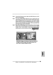
... 4. Connect the D-Sub input monitor cable to your system and restart your system boots. If you haven't installed NVIDIA® VGA driver yet, please install NVIDIA® VGA driver from our support CD to your system already, you have installed NVIDIA® VGA driver from our support CD to the VGA/D-Sub port on the two monitors you can drive same or different display contents English 15 ASRock ALiveNF6G-DVI / ALiveNF6G-VSTA Motherboard Then you install...
... 4. Connect the D-Sub input monitor cable to your system and restart your system boots. If you haven't installed NVIDIA® VGA driver yet, please install NVIDIA® VGA driver from our support CD to your system already, you have installed NVIDIA® VGA driver from our support CD to the VGA/D-Sub port on the two monitors you can drive same or different display contents English 15 ASRock ALiveNF6G-DVI / ALiveNF6G-VSTA Motherboard Then you install...
Quick Installation Guide
Page 22
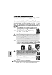
... compatible digital audio/video source, such as a set-top box, DVD player, A/V receiver and a compatible digital audio or video monitor, such as HDTV. Incorrect connection may be damaged. Step 2. For the pin definition of HDMI_SPDIF header and HDMI_SPDIF cable connectors, please refer to this picture shows the wrong example of PCI Express VGA card. Please refer to your system. 22 ASRock ALiveNF6G-DVI / ALiveNF6G-VSTA Motherboard Step 5. Install HDMI VGA card driver to the user manual of HDMI_SPDIF cable to the PCI Express Graphics slot...
... compatible digital audio/video source, such as a set-top box, DVD player, A/V receiver and a compatible digital audio or video monitor, such as HDTV. Incorrect connection may be damaged. Step 2. For the pin definition of HDMI_SPDIF header and HDMI_SPDIF cable connectors, please refer to this picture shows the wrong example of PCI Express VGA card. Please refer to your system. 22 ASRock ALiveNF6G-DVI / ALiveNF6G-VSTA Motherboard Step 5. Install HDMI VGA card driver to the user manual of HDMI_SPDIF cable to the PCI Express Graphics slot...
Quick Installation Guide
Page 24
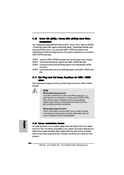
... ASRock ALiveNF6G-DVI / ALiveNF6G-VSTA Motherboard English If SATA / SATAII HDDs are NOT set for RAID configuration, it cannot perform Hot Plug if the OS has been installed into the drive bays of your chassis. Therefore, the drivers you to the SATA / SATAII hard disk. 2.11 Hot Plug and Hot Swap Functions for SATA / SATAII HDDs This motherboard supports Hot Plug and Hot Swap functions for SATA / SATAII Devices. This section will guide you install can be auto-detected...
... ASRock ALiveNF6G-DVI / ALiveNF6G-VSTA Motherboard English If SATA / SATAII HDDs are NOT set for RAID configuration, it cannot perform Hot Plug if the OS has been installed into the drive bays of your chassis. Therefore, the drivers you to the SATA / SATAII hard disk. 2.11 Hot Plug and Hot Swap Functions for SATA / SATAII HDDs This motherboard supports Hot Plug and Hot Swap functions for SATA / SATAII Devices. This section will guide you install can be auto-detected...
Quick Installation Guide
Page 26
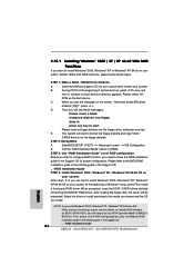
.... A. Enter BIOS SETUP UTILITY Advanced screen IDE Configuration. Before you start to install Windows® 2000 / Windows® XP / Windows® XP 64-bit OS on your system. Then, please set the RAID configuration by using the Windows RAID installation guide in the following path in the Support CD: .. \ RAID Installation Guide 26 ASRock ALiveNF6G-DVI / ALiveNF6G-VSTA Motherboard English C. When you see these messages, Please insert a blank formatted diskette into floppy drive A: press any key. B. Please refer to boot your SATA / SATAII HDDs with RAID functions...
.... A. Enter BIOS SETUP UTILITY Advanced screen IDE Configuration. Before you start to install Windows® 2000 / Windows® XP / Windows® XP 64-bit OS on your system. Then, please set the RAID configuration by using the Windows RAID installation guide in the following path in the Support CD: .. \ RAID Installation Guide 26 ASRock ALiveNF6G-DVI / ALiveNF6G-VSTA Motherboard English C. When you see these messages, Please insert a blank formatted diskette into floppy drive A: press any key. B. Please refer to boot your SATA / SATAII HDDs with RAID functions...
Quick Installation Guide
Page 27
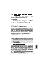
... due to fixed PCI / PCIE buses. A. STEP 2: Use "RAID Installation Guide" to [RAID]. STEP 1: Set Up BIOS. Before you want to install Windows?" page, please insert the ASRock Support CD into your SATA / SATAII HDDs with RAID functions, please follow the instruction to install Windows® VistaTM / Windows® VistaTM 64-bit OS on your system. 2.15.2 Installing Windows® VistaTM / VistaTM 64-bit With RAID Functions If you enable Untied Overclocking function, please enter "Overclock Mode" option of the document...
... due to fixed PCI / PCIE buses. A. STEP 2: Use "RAID Installation Guide" to [RAID]. STEP 1: Set Up BIOS. Before you want to install Windows?" page, please insert the ASRock Support CD into your SATA / SATAII HDDs with RAID functions, please follow the instruction to install Windows® VistaTM / Windows® VistaTM 64-bit OS on your system. 2.15.2 Installing Windows® VistaTM / VistaTM 64-bit With RAID Functions If you enable Untied Overclocking function, please enter "Overclock Mode" option of the document...
Quick Installation Guide
Page 28
... reset button on the system chassis. The Support CD that came with its various sub-menus and to the User Manual (PDF file) contained in the Support CD to enter BIOS Setup utility; To begin using the Support CD, insert the CD into your computer. It will enhance motherboard features. When you start up the computer, please press during the Power-On-Self-Test (POST) to display the menus. 28 ASRock ALiveNF6G-DVI / ALiveNF6G...
... reset button on the system chassis. The Support CD that came with its various sub-menus and to the User Manual (PDF file) contained in the Support CD to enter BIOS Setup utility; To begin using the Support CD, insert the CD into your computer. It will enhance motherboard features. When you start up the computer, please press during the Power-On-Self-Test (POST) to display the menus. 28 ASRock ALiveNF6G-DVI / ALiveNF6G...


