
User Guide
Page 1
Baseline Switch 2226-SFP Plus Baseline Switch 2426-PWR Plus Baseline Switch 2250-SFP Plus Installation and User Guide Installations- und Bedienungsanleitung 3CBLSF26 3CBLSF26PWR 3CBLSF50 www.3Com.com Part No. 10016622 Published May 2008
Baseline Switch 2226-SFP Plus Baseline Switch 2426-PWR Plus Baseline Switch 2250-SFP Plus Installation and User Guide Installations- und Bedienungsanleitung 3CBLSF26 3CBLSF26PWR 3CBLSF50 www.3Com.com Part No. 10016622 Published May 2008
User Guide
Page 3
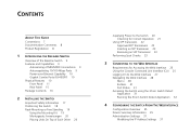
CONTENTS ABOUT THIS GUIDE Conventions 7 Documentation Comments 8 Product Registration 8 1 INTRODUCING THE BASELINE SWITCH Overview of the Baseline Switch 9 Features and Capabilities 9 Autosensing of MDI/MDIX Connections 9 Autonegotiating 10/100 Mbps Ports 9 Power-over-Ethernet ... Navigating the Web Interface 28 Menu 28 Buttons 31 Port Status 31 Accessing the Switch using the 3Com Switch Detect Application 31 Running the 3Com Switch Detect Application 32 4 CONFIGURING THE SWITCH FROM THE WEB INTERFACE Configuration Overview 35 Device Summary Information 35 Administration Settings 37 ...
CONTENTS ABOUT THIS GUIDE Conventions 7 Documentation Comments 8 Product Registration 8 1 INTRODUCING THE BASELINE SWITCH Overview of the Baseline Switch 9 Features and Capabilities 9 Autosensing of MDI/MDIX Connections 9 Autonegotiating 10/100 Mbps Ports 9 Power-over-Ethernet ... Navigating the Web Interface 28 Menu 28 Buttons 31 Port Status 31 Accessing the Switch using the 3Com Switch Detect Application 31 Running the 3Com Switch Detect Application 32 4 CONFIGURING THE SWITCH FROM THE WEB INTERFACE Configuration Overview 35 Device Summary Information 35 Administration Settings 37 ...
User Guide
Page 7
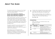
... with your 3Com Switch and perform initial management configurations. Most user guides and release notes are provided for installing and setting up network equipment; Where features vary significantly between the switches, examples are available in this guide. It covers the following switches: Baseline Switch 2226-SFP Plus (3CBLSF26) Baseline Switch 2426-PWR Plus (3CBLSF26PWR) Baseline Switch 2250-SFP Plus (3CBLSF50) Unless noted...
... with your 3Com Switch and perform initial management configurations. Most user guides and release notes are provided for installing and setting up network equipment; Where features vary significantly between the switches, examples are available in this guide. It covers the following switches: Baseline Switch 2226-SFP Plus (3CBLSF26) Baseline Switch 2426-PWR Plus (3CBLSF26PWR) Baseline Switch 2250-SFP Plus (3CBLSF50) Unless noted...
User Guide
Page 8
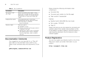
... term at this guide, you must type something, and then press Return or Enter. Please e-mail comments about this document to 3Com at: pddtechpubs_comments@3Com.com Please include the following information when contacting us . Documentation Comments Your suggestions are linked with a plus sign (+). Product Registration You... ■ Document title ■ Document part number (on the title page) ■ Page number (if appropriate) Example: ■ Baseline Switch 2426-PWR Plus User Guide ■ Part number: 10016622 ■ Page 25 Please note that we can now register your...
... term at this guide, you must type something, and then press Return or Enter. Please e-mail comments about this document to 3Com at: pddtechpubs_comments@3Com.com Please include the following information when contacting us . Documentation Comments Your suggestions are linked with a plus sign (+). Product Registration You... ■ Document title ■ Document part number (on the title page) ■ Page number (if appropriate) Example: ■ Baseline Switch 2426-PWR Plus User Guide ■ Part number: 10016622 ■ Page 25 Please note that we can now register your...
User Guide
Page 9
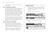
... 24 or 48 shielded RJ-45, 10/100 Mbps auto-negotiating ports and 2 Gigabit combo ports (comprised of the 3Com Baseline Switch 2226-SFP Plus, 3Com Baseline Switch 2426-PWR Plus, and 3Com Baseline Switch 2250-SFP Plus. Autonegotiating 10/100 Mbps Ports Each 10/100 Mbps port automatically determines the speed and duplex mode of the device. It also...
... 24 or 48 shielded RJ-45, 10/100 Mbps auto-negotiating ports and 2 Gigabit combo ports (comprised of the 3Com Baseline Switch 2226-SFP Plus, 3Com Baseline Switch 2426-PWR Plus, and 3Com Baseline Switch 2250-SFP Plus. Autonegotiating 10/100 Mbps Ports Each 10/100 Mbps port automatically determines the speed and duplex mode of the device. It also...
User Guide
Page 10
...points, which translates into greater network availability. Figure 1 3CBLSF26 Front and Rear Panels Figure 2 3CBLSF26PWR Front and Rear Panels 10 INTRODUCING THE BASELINE SWITCH 10/100 Mbps ports can only operate in full duplex mode. When an SFP port is in any combination. The 1000 Mbps connections can... operate in these diagrams refer to a port can directly draw power from the Switch over -Ethernet (PoE) standard. Gigabit Combo Ports (RJ-45/SFP) The 2 Gigabit combo ports support fiber Gigabit Ethernet short-wave (SX)...
...points, which translates into greater network availability. Figure 1 3CBLSF26 Front and Rear Panels Figure 2 3CBLSF26PWR Front and Rear Panels 10 INTRODUCING THE BASELINE SWITCH 10/100 Mbps ports can only operate in full duplex mode. When an SFP port is in any combination. The 1000 Mbps connections can... operate in these diagrams refer to a port can directly draw power from the Switch over -Ethernet (PoE) standard. Gigabit Combo Ports (RJ-45/SFP) The 2 Gigabit combo ports support fiber Gigabit Ethernet short-wave (SX)...
User Guide
Page 11
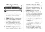
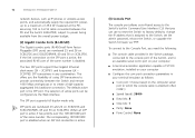
...traditional PBX or public telephone network. Nur RJ-45-Datenanscluße, Telefonnetzsysteme or Netztelefone an diese Steckdosen anschließen. The 3CBLSF26PWR Switch also supports IEEE 802.3af-2003 standard (802.3af) and pre-standard P802.3at DTE Power via MDI Enhancements (PoE+). Only connect.... Each port supports automatic MDI/MDI-X detection and can detect connected 802.3af/at-compliant Figure 3 3CBLSF50 Front and Rear Panels Front Panel The front panel of the Switch contains a series of indicator lights (LEDs) that help describe the state of the connected device. These...
...traditional PBX or public telephone network. Nur RJ-45-Datenanscluße, Telefonnetzsysteme or Netztelefone an diese Steckdosen anschließen. The 3CBLSF26PWR Switch also supports IEEE 802.3af-2003 standard (802.3af) and pre-standard P802.3at DTE Power via MDI Enhancements (PoE+). Only connect.... Each port supports automatic MDI/MDI-X detection and can detect connected 802.3af/at-compliant Figure 3 3CBLSF50 Front and Rear Panels Front Panel The front panel of the Switch contains a series of indicator lights (LEDs) that help describe the state of the connected device. These...
User Guide
Page 12
... via the Web interface. To connect to the Console Port, you can be configured via TFTP. 12 INTRODUCING THE BASELINE SWITCH network devices, such as follows: ■ Com port: Choose based on 3CBLSF50. The default active port is attached (often COM1) ■ Speed (baud): 38400 ■ Data bits: 8 ■ ...IP address that you need the following: ■ The console cable provided in the Switch package, connected to the console port of the Switch, and to an available serial (com) port on 3CBLSF50. SFP ports are numbered 25 and 26 on 3CBLSF26 and 3CBLSF26PWR, 49 and 50 on...
... via the Web interface. To connect to the Console Port, you can be configured via TFTP. 12 INTRODUCING THE BASELINE SWITCH network devices, such as follows: ■ Com port: Choose based on 3CBLSF50. The default active port is attached (often COM1) ■ Speed (baud): 38400 ■ Data bits: 8 ■ ...IP address that you need the following: ■ The console cable provided in the Switch package, connected to the console port of the Switch, and to an available serial (com) port on 3CBLSF50. SFP ports are numbered 25 and 26 on 3CBLSF26 and 3CBLSF26PWR, 49 and 50 on...
User Guide
Page 14
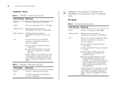
... attached device is powered on the local device. likewise, RX on the port at 1000 Mbps. Flashing Green Packets are not swapped. 14 INTRODUCING THE BASELINE SWITCH 1000BASE-T Mode Table 3 1000BASE-T Link/Activity Status LEDs Link/Activity Meaning Green The link is operating at 1000 Mbps.
... attached device is powered on the local device. likewise, RX on the port at 1000 Mbps. Flashing Green Packets are not swapped. 14 INTRODUCING THE BASELINE SWITCH 1000BASE-T Mode Table 3 1000BASE-T Link/Activity Status LEDs Link/Activity Meaning Green The link is operating at 1000 Mbps.
User Guide
Page 15
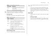
... correctly. ■ If the unit still does not operate, contact your supplier. (8) Self-adhesive Pads The unit is a valid link on the underside of the Switch. The SFP module will only disable the 1000BASE-T interface once there is supplied with the unit. Physical Features 15 Do not apply the pads if... SFP/Duplex Meaning Green The SFP module is supplied with four self-adhesive rubber pads. Only use . If the unit is in fail-safe mode. Switch is to be part of a free-standing stack, apply the pads to each marked corner area on the module. (7) Power LED The Power LED ...
... correctly. ■ If the unit still does not operate, contact your supplier. (8) Self-adhesive Pads The unit is a valid link on the underside of the Switch. The SFP module will only disable the 1000BASE-T interface once there is supplied with the unit. Physical Features 15 Do not apply the pads if... SFP/Duplex Meaning Green The SFP module is supplied with four self-adhesive rubber pads. Only use . If the unit is in fail-safe mode. Switch is to be part of a free-standing stack, apply the pads to each marked corner area on the module. (7) Power LED The Power LED ...
User Guide
Page 16
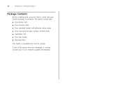
The Switch comes with: ■ One power cord ■ One console cable ■ Four standard height, self-adhesive rubber pads ■ One mounting kit (part number 123193-104) ■ Installation CD ■ This User Guide ■ Warranty flyer The Switch is complete. If any of the above items are damaged or missing, contact your Switch package is powered from the AC supply. 16 INTRODUCING THE BASELINE SWITCH Package Contents Before installing and using the Switch, verify that your 3Com network supplier immediately.
The Switch comes with: ■ One power cord ■ One console cable ■ Four standard height, self-adhesive rubber pads ■ One mounting kit (part number 123193-104) ■ Installation CD ■ This User Guide ■ Warranty flyer The Switch is complete. If any of the above items are damaged or missing, contact your Switch package is powered from the AC supply. 16 INTRODUCING THE BASELINE SWITCH Package Contents Before installing and using the Switch, verify that your 3Com network supplier immediately.
User Guide
Page 17
...;a encontradas no Manual 3Com Switch Family Safety and Regulatory Information (Translation for this product. 2 INSTALLING THE SWITCH This chapter contains information that was included with this would be: Informações de Segurança e Regulatórias da Famila de Switches 3Com) incluido no produto.... Du kan hitta denna manual på den CD-ROM som följde med din switch. Vous pouvez aussi le télécharger sur le site Web de 3Com à: www.3Com.com Wichtige Sicherheits Informationen Bitte wenden...
...;a encontradas no Manual 3Com Switch Family Safety and Regulatory Information (Translation for this product. 2 INSTALLING THE SWITCH This chapter contains information that was included with this would be: Informações de Segurança e Regulatórias da Famila de Switches 3Com) incluido no produto.... Du kan hitta denna manual på den CD-ROM som följde med din switch. Vous pouvez aussi le télécharger sur le site Web de 3Com à: www.3Com.com Wichtige Sicherheits Informationen Bitte wenden...
User Guide
Page 18
... możliwość pobrania instrukcji bezpośrednio ze strony internetowej www.3Com.com Positioning the Switch The Switch is accessible and cables can interfere with the Switch. Alternatively, the Switch can be rack-mounted in a standard 19-inch equipment rack. Electromagnetic fields can ... Importante Avviso di Sicurezza Vi preghiamo di leggere attentamente e seguire le istruzioni indicate nel manuale di sicurezza "3Com Switch Family Safety and Regulatory Information", che troverete incluso a questo prodotto. Puó trovare il suddetto manuale nel CD-ROM allegato ...
... możliwość pobrania instrukcji bezpośrednio ze strony internetowej www.3Com.com Positioning the Switch The Switch is accessible and cables can interfere with the Switch. Alternatively, the Switch can be rack-mounted in a standard 19-inch equipment rack. Electromagnetic fields can ... Importante Avviso di Sicurezza Vi preghiamo di leggere attentamente e seguire le istruzioni indicate nel manuale di sicurezza "3Com Switch Family Safety and Regulatory Information", che troverete incluso a questo prodotto. Puó trovare il suddetto manuale nel CD-ROM allegato ...
User Guide
Page 19
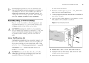
...high and will fit in the mounting kit and fully tighten with a suitable screwdriver. Rack-Mounting or Free-Standing 19 To rack-mount the Switch: 1 Place the unit the right way up on a hard, flat surface with the front facing towards you should take note of the guidelines... Static discharge can be installed above the larger ones. CAUTION: If installing the Switch in a free-standing stack of the unit, if already fitted. CAUTION: Disconnect all cables from the underside of different size Baseline or Superstack 3 units, the smaller units must be free standing. Remove the ...
...high and will fit in the mounting kit and fully tighten with a suitable screwdriver. Rack-Mounting or Free-Standing 19 To rack-mount the Switch: 1 Place the unit the right way up on a hard, flat surface with the front facing towards you should take note of the guidelines... Static discharge can be installed above the larger ones. CAUTION: If installing the Switch in a free-standing stack of the unit, if already fitted. CAUTION: Disconnect all cables from the underside of different size Baseline or Superstack 3 units, the smaller units must be free standing. Remove the ...
User Guide
Page 21
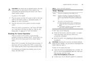
...8 Power LED POST Indications Status Meaning Green The unit is connected correctly, and then try powering on the Switch again ■ If the Switch still does not operate, contact your 3Com network supplier If POST fails, try the following summarizes the possible colors for more information. 2 Plug the ...turns yellow after POST, it means that the power cord is powered on and ready to reconfigure the Switch after POST. CAUTION: Resetting the Switch to its factory defaults erases all your 3Com network supplier for a solution. During POST, the Power LED on self-test (POST). Off The ...
...8 Power LED POST Indications Status Meaning Green The unit is connected correctly, and then try powering on the Switch again ■ If the Switch still does not operate, contact your 3Com network supplier If POST fails, try the following summarizes the possible colors for more information. 2 Plug the ...turns yellow after POST, it means that the power cord is powered on and ready to reconfigure the Switch after POST. CAUTION: Resetting the Switch to its factory defaults erases all your 3Com network supplier for a solution. During POST, the Power LED on self-test (POST). Off The ...
User Guide
Page 22
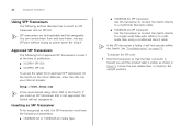
... Hold the transceiver so that is faulty, it . 22 INSTALLING THE SWITCH Using SFP Tranceivers The following sections describe how to insert an SFP transceiver into your Internet browser: http://www.3Com.com 3Com recommends using a conditioned launch cable. Ensure the wire release lever is ...list of approved SFP transceivers is closed (in the Switch. See "Troubleshooting" on the 3Com Web site, enter this transceiver to connect the Switch directly to a single mode fiber-optic cable or to multimode fiber using 3Com SFPs in the upright position). Approved SFP Transceivers The ...
... Hold the transceiver so that is faulty, it . 22 INSTALLING THE SWITCH Using SFP Tranceivers The following sections describe how to insert an SFP transceiver into your Internet browser: http://www.3Com.com 3Com recommends using a conditioned launch cable. Ensure the wire release lever is ...list of approved SFP transceivers is closed (in the Switch. See "Troubleshooting" on the 3Com Web site, enter this transceiver to connect the Switch directly to a single mode fiber-optic cable or to multimode fiber using 3Com SFPs in the upright position). Approved SFP Transceivers The ...
User Guide
Page 23
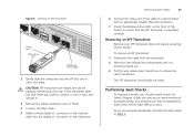
..., if fitted. 4 Connect the fiber cable. 5 Attach a male duplex LC connector on the network cable into the duplex LC connector on users. 3Com recommends periodically checking the items listed in Table 9. Removing an SFP Transceiver Removing an SFP transceiver does not require powering off the... the Module Active LEDs on the front of a possible failure; CAUTION: SFP transceivers are keyed and can give you an early warning of the Switch to ensure that the SFP transceiver is pointing toward you. 3 Pull the wire release lever toward you should slide out easily. Performing Spot Checks At...
..., if fitted. 4 Connect the fiber cable. 5 Attach a male duplex LC connector on the network cable into the duplex LC connector on users. 3Com recommends periodically checking the items listed in Table 9. Removing an SFP Transceiver Removing an SFP transceiver does not require powering off the... the Module Active LEDs on the front of a possible failure; CAUTION: SFP transceivers are keyed and can give you an early warning of the Switch to ensure that the SFP transceiver is pointing toward you. 3 Pull the wire release lever toward you should slide out easily. Performing Spot Checks At...
User Guide
Page 24
Cooling fan (3CBLSF26PWR only) Where possible, check that the cooling fan is fitted near to Check Cabling Check that all external cabling connections are secure and that no cables are pulled taut. If you experience any problems operating the Switch, refer to the unit. 24 INSTALLING THE SWITCH Table 9 Items to the front right hand side of the unit (when viewed from the front). The fan is operating by listening to "Troubleshooting" on page 75.
Cooling fan (3CBLSF26PWR only) Where possible, check that the cooling fan is fitted near to Check Cabling Check that all external cabling connections are secure and that no cables are pulled taut. If you experience any problems operating the Switch, refer to the unit. 24 INSTALLING THE SWITCH Table 9 Items to the front right hand side of the unit (when viewed from the front). The fan is operating by listening to "Troubleshooting" on page 75.

User Guide
Page 25
... the admin password, change the IP address that is necessary to the Web interface using the 3Com Switch Detect Application The Switch support the following : ■ The console cable that was supplied with your Switch. ■ The 3Com Switch Detect application, that is connected to the Switch and that has a Web browser. If you only want the...
... the admin password, change the IP address that is necessary to the Web interface using the 3Com Switch Detect Application The Switch support the following : ■ The console cable that was supplied with your Switch. ■ The 3Com Switch Detect application, that is connected to the Switch and that has a Web browser. If you only want the...
User Guide
Page 26
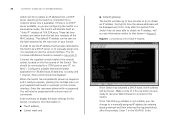
... itself an "Auto IP" address of it is not suitable, you are taken from a DHCP server (assuming the Switch is ready to operate, pressing the carridge return on your Switch. Make a note of 169.254.xx.yy. These last two numbers are ready to use the console interface. This... should be displayed as 0.0.0.0. 26 CHAPTER 3: CONNECTING TO THE WEB INTERFACE switch will try to obtain an IP address. This default IP address can change to a manually assigned IP address by a DHCP server, or to display...
... itself an "Auto IP" address of it is not suitable, you are taken from a DHCP server (assuming the Switch is ready to operate, pressing the carridge return on your Switch. Make a note of 169.254.xx.yy. These last two numbers are ready to use the console interface. This... should be displayed as 0.0.0.0. 26 CHAPTER 3: CONNECTING TO THE WEB INTERFACE switch will try to obtain an IP address. This default IP address can change to a manually assigned IP address by a DHCP server, or to display...


