User Guide
Page 3
... 22 Removing an SFP Transceiver 23 Performing Spot Checks 23 3 CONNECTING TO THE WEB INTERFACE Requirements for Accessing the Web Interface 25 Using the Console Command Line Interface (CLI) 25 Logging On to the Web Interface 27 Navigating the Web Interface 28 Menu 28 Buttons 31 Port Status 31 Accessing the Switch using the 3Com Switch Detect Application 31 Running the 3Com Switch Detect Application 32 4 CONFIGURING THE SWITCH FROM THE WEB INTERFACE Configuration Overview 35 Device Summary Information 35 Administration Settings 37 Modifying the IP Address Settings...
... 22 Removing an SFP Transceiver 23 Performing Spot Checks 23 3 CONNECTING TO THE WEB INTERFACE Requirements for Accessing the Web Interface 25 Using the Console Command Line Interface (CLI) 25 Logging On to the Web Interface 27 Navigating the Web Interface 28 Menu 28 Buttons 31 Port Status 31 Accessing the Switch using the 3Com Switch Detect Application 31 Running the 3Com Switch Detect Application 32 4 CONFIGURING THE SWITCH FROM THE WEB INTERFACE Configuration Overview 35 Device Summary Information 35 Administration Settings 37 Modifying the IP Address Settings...
User Guide
Page 4
... Setup 38 Backup Configuration 38 Restore Configuration 39 Firmware Upgrade 39 Reset 40 System Access 40 System Name 43 System Time 43 SNMP 43 Configuring VLANs 44 VLAN 45 Forwarding Tagged/Untagged Frames 49 Sample VLAN Configurations 49 Spanning Tree 51 IGMP Snooping & Query 54 Broadcast Storm 55 QoS VoIP Traffic Settings 56 PoE (3CBLSF26-PWR only) 59 Configuring Port Settings 60 Administration 60 Link Aggregation 63 Statistics 66 Security 66 RADIUS Client 66 802.1X Settings 67 Monitoring 69 Address Table 69 Port Mirroring 70 Cable Diagnostics 72 5 TROUBLESHOOTING Resetting to Factory...
... Setup 38 Backup Configuration 38 Restore Configuration 39 Firmware Upgrade 39 Reset 40 System Access 40 System Name 43 System Time 43 SNMP 43 Configuring VLANs 44 VLAN 45 Forwarding Tagged/Untagged Frames 49 Sample VLAN Configurations 49 Spanning Tree 51 IGMP Snooping & Query 54 Broadcast Storm 55 QoS VoIP Traffic Settings 56 PoE (3CBLSF26-PWR only) 59 Configuring Port Settings 60 Administration 60 Link Aggregation 63 Statistics 66 Security 66 RADIUS Client 66 802.1X Settings 67 Monitoring 69 Address Table 69 Port Mirroring 70 Cable Diagnostics 72 5 TROUBLESHOOTING Resetting to Factory...
User Guide
Page 7
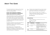
... Netzwerkkomponenten verantwortlich sind; Where features vary significantly between the switches, examples are based on the 3Com World Wide Web site: www.3Com.com Conventions Table 1 and Table 2 list conventions that alerts you to an application, system, or device Warning Information that are shipped with your 3Com Switch and perform initial management configurations. Device drawings, screen captures and command line interface examples are provided for installing and setting up network equipment;
... Netzwerkkomponenten verantwortlich sind; Where features vary significantly between the switches, examples are based on the 3Com World Wide Web site: www.3Com.com Conventions Table 1 and Table 2 list conventions that alerts you to an application, system, or device Warning Information that are shipped with your 3Com Switch and perform initial management configurations. Device drawings, screen captures and command line interface examples are provided for installing and setting up network equipment;
User Guide
Page 12
... -band access to the Switch, set the admin password, reboot the Switch, or upgrade the Switch firmware via the Web interface. The corresponding 10/100/1000 port is disabled when an SFP link connection is assigned to the Switch's built-in any combination. The two SFP ports support fiber Gigabit Ethernet short-wave (SX - 3CSFP91) and long-wave (LX - 3CSFP92) SFP transceivers in Command Line Interface (CLI) that is active. (3) Console Port The console port allows out-of the same number. If the link connection on 3CBLSF50.
... -band access to the Switch, set the admin password, reboot the Switch, or upgrade the Switch firmware via the Web interface. The corresponding 10/100/1000 port is disabled when an SFP link connection is assigned to the Switch's built-in any combination. The two SFP ports support fiber Gigabit Ethernet short-wave (SX - 3CSFP91) and long-wave (LX - 3CSFP92) SFP transceivers in Command Line Interface (CLI) that is active. (3) Console Port The console port allows out-of the same number. If the link connection on 3CBLSF50.
User Guide
Page 21
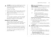
... 3Com network supplier If POST fails, try the following summarizes the possible colors for more information. This is powered on, the Power LED lights up , refer to use. If the Power LED does not light up . When POST is in fail-safe mode. Supplying Power to the Switch 21 Table 8 Power LED POST Indications Status Meaning Green The unit is powered on and ready to "(7) Power LED" on page 15 for Correct Operation After you reset...
... 3Com network supplier If POST fails, try the following summarizes the possible colors for more information. This is powered on, the Power LED lights up , refer to use. If the Power LED does not light up . When POST is in fail-safe mode. Supplying Power to the Switch 21 Table 8 Power LED POST Indications Status Meaning Green The unit is powered on and ready to "(7) Power LED" on page 15 for Correct Operation After you reset...
User Guide
Page 26
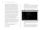
26 CHAPTER 3: CONNECTING TO THE WEB INTERFACE switch will try to obtain an IP address. This default IP address can change to a manually assigned IP address by a DHCP server, or to manually assign one is covered in Figure 6. Figure 6 CLI Summary with no parity and 1 stop bit. The CLI Command Reference Guide is available). Enter the username admin with Default IP Address If the Switch has obtained a DHCP lease, the IP address will be connected to a COM port on...
26 CHAPTER 3: CONNECTING TO THE WEB INTERFACE switch will try to obtain an IP address. This default IP address can change to a manually assigned IP address by a DHCP server, or to manually assign one is covered in Figure 6. Figure 6 CLI Summary with no parity and 1 stop bit. The CLI Command Reference Guide is available). Enter the username admin with Default IP Address If the Switch has obtained a DHCP lease, the IP address will be connected to a COM port on...

User Guide
Page 31
... and modifies the current port traffic monitoring configuration. ■ Removes port traffic monitoring settings. Contains tabs that allow you to: ■ Display cable diagnostics information for all ports. ■ Configure system authentication settings. Displays MAC address table information for all ports. ■ Perform cable diagnostics for the following buttons may appear: ■ Apply - Displays 3Com contact information and describes how to use . Menu Item 802.1X Settings Monitoring Address Table Port Mirroring Cable Diagnostics Help Log Out Description Contains...
... and modifies the current port traffic monitoring configuration. ■ Removes port traffic monitoring settings. Contains tabs that allow you to: ■ Display cable diagnostics information for all ports. ■ Configure system authentication settings. Displays MAC address table information for all ports. ■ Perform cable diagnostics for the following buttons may appear: ■ Apply - Displays 3Com contact information and describes how to use . Menu Item 802.1X Settings Monitoring Address Table Port Mirroring Cable Diagnostics Help Log Out Description Contains...
User Guide
Page 32
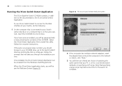
... to the Web interface of the CD-ROM. Follow the onscreen instructions. If the auto-run program does not start, you will be accessed from the Windows Start/Programs list. 32 CHAPTER 3: CONNECTING TO THE WEB INTERFACE Running the 3Com Switch Detect Application The 3Com Baseline Switch CD-ROM contains, in addition to install the utility. To use 3Com Switch Detect to connect to your Switch (either directly or on setup.exe.
... to the Web interface of the CD-ROM. Follow the onscreen instructions. If the auto-run program does not start, you will be accessed from the Windows Start/Programs list. 32 CHAPTER 3: CONNECTING TO THE WEB INTERFACE Running the 3Com Switch Detect Application The 3Com Baseline Switch CD-ROM contains, in addition to install the utility. To use 3Com Switch Detect to connect to your Switch (either directly or on setup.exe.
User Guide
Page 35
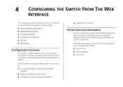
... to configure the Switch's advanced features. You only need to access the Web interface if you want the Switch to function as a basic Layer 2 switch, you log on to the Web interface, provides a snapshot of the Switch's basic settings and versions of current components. Topics include: ■ Device Summary Information ■ Administration Settings ■ Configuring VLANs ■ Configuring Port Settings ■ Security ■ Monitoring Configuration Overview The Switch is shipped ready for use. A screen...
... to configure the Switch's advanced features. You only need to access the Web interface if you want the Switch to function as a basic Layer 2 switch, you log on to the Web interface, provides a snapshot of the Switch's basic settings and versions of current components. Topics include: ■ Device Summary Information ■ Administration Settings ■ Configuring VLANs ■ Configuring Port Settings ■ Security ■ Monitoring Configuration Overview The Switch is shipped ready for use. A screen...
User Guide
Page 37
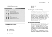
... , for the first time, it - Figure 17 Color Key Administration Settings The Administration menu includes eight administration items: ■ IP Setup ■ Backup & Restore ■ Firmware Upgrade ■ Reset ■ System Access Administration Settings 37 ■ System Name ■ System Time ■ SNMP Modifying the IP Address Settings To enable devices on the Switch for a period of the color coding. either obtain an IP address from a DHCP server (default operation), or if...
... , for the first time, it - Figure 17 Color Key Administration Settings The Administration menu includes eight administration items: ■ IP Setup ■ Backup & Restore ■ Firmware Upgrade ■ Reset ■ System Access Administration Settings 37 ■ System Name ■ System Time ■ SNMP Modifying the IP Address Settings To enable devices on the Switch for a period of the color coding. either obtain an IP address from a DHCP server (default operation), or if...
User Guide
Page 38
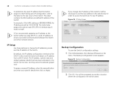
... out). IP Setup Use these settings to access the Switch at it's new IP address. In this new address in the web browser in order to change the IP address of the Switch. This label contains the MAC address and default IP address of the Switch. If you change the IP addressing mode and the IP address of the Switch. Figure 18 IP Setup Screen Backup Configuration To save the Switch configuration settings: 1 Click Administration, then Backup & Restore on Apply.
... out). IP Setup Use these settings to access the Switch at it's new IP address. In this new address in the web browser in order to change the IP address of the Switch. This label contains the MAC address and default IP address of the Switch. If you change the IP addressing mode and the IP address of the Switch. Figure 18 IP Setup Screen Backup Configuration To save the Switch configuration settings: 1 Click Administration, then Backup & Restore on Apply.
User Guide
Page 40
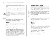
... properly afterwards. System Access Click Administration, then System Access on Initialize, discard IP setting will be reset. 40 CHAPTER 4: CONFIGURING THE SWITCH FROM THE WEB INTERFACE A progress screen displays while the upgrade is permanently green. No configuration settings will return the Switch to the factory default configuration, including the IP address mode which shall be deleted). The default admin account settings are: ■ User name - CAUTION: Do not interrupt power to go through the...
... properly afterwards. System Access Click Administration, then System Access on Initialize, discard IP setting will be reset. 40 CHAPTER 4: CONFIGURING THE SWITCH FROM THE WEB INTERFACE A progress screen displays while the upgrade is permanently green. No configuration settings will return the Switch to the factory default configuration, including the IP address mode which shall be deleted). The default admin account settings are: ■ User name - CAUTION: Do not interrupt power to go through the...

User Guide
Page 41
... actively manage the Switch, 3Com recommends that user. The password can be up to your network. User Summary Displays the list of user names and their access level. Even if you do not access the Web interface, 3Com recommends that you set it, refer to "Resetting to Factory Defaults" on page 75 for information on how to regain access to create a user and define the access level and password for that you first configure the Switch...
... actively manage the Switch, 3Com recommends that user. The password can be up to your network. User Summary Displays the list of user names and their access level. Even if you do not access the Web interface, 3Com recommends that you set it, refer to "Resetting to Factory Defaults" on page 75 for information on how to regain access to create a user and define the access level and password for that you first configure the Switch...
User Guide
Page 46
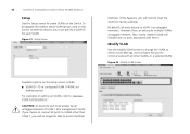
... setting up VLANs, refer to "Sample VLAN Configurations". Modify VLAN Use the Modify VLAN screen to change the VLAN to which a port belongs, and configure the port to communicate with them. CAUTION: At least one port must specify a VLAN ID for each VLAN. Figure 32 Modify VLAN Screen Also, newly created VLANs will need to reset the Switch to factory settings. Figure 31 Setup Screen Available options on the Switch. 46 CHAPTER 4: CONFIGURING THE SWITCH FROM THE WEB INTERFACE Setup Use...
... setting up VLANs, refer to "Sample VLAN Configurations". Modify VLAN Use the Modify VLAN screen to change the VLAN to which a port belongs, and configure the port to communicate with them. CAUTION: At least one port must specify a VLAN ID for each VLAN. Figure 32 Modify VLAN Screen Also, newly created VLANs will need to reset the Switch to factory settings. Figure 31 Setup Screen Available options on the Switch. 46 CHAPTER 4: CONFIGURING THE SWITCH FROM THE WEB INTERFACE Setup Use...
User Guide
Page 50
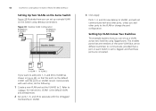
... 4: CONFIGURING THE SWITCH FROM THE WEB INTERFACE Setting Up Two VLANs on the Same Switch Figure 38 illustrates how you can set up a simple VLAN on the Switch using Tagged ports. Setting Up VLAN Across Two Switches This example explains how you want to add ports 1, 3, and 26 to VLAN2 (as shown in VLAN 2 Baseline Switch 3 Click Apply. Server Server in VLAN 1 in VLAN 2 If you can set to 2. VLAN1 is set up a VLAN across two Switches using desktop connections. Figure...
... 4: CONFIGURING THE SWITCH FROM THE WEB INTERFACE Setting Up Two VLANs on the Same Switch Figure 38 illustrates how you can set up a simple VLAN on the Switch using Tagged ports. Setting Up VLAN Across Two Switches This example explains how you want to add ports 1, 3, and 26 to VLAN2 (as shown in VLAN 2 Baseline Switch 3 Click Apply. Server Server in VLAN 1 in VLAN 2 If you can set to 2. VLAN1 is set up a VLAN across two Switches using desktop connections. Figure...
User Guide
Page 71
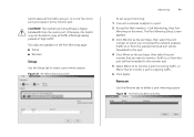
... Remove tab to create a port mirror session. Otherwise, the Switch may not be able to a port. 2 Access the Web interface. Figure 67 Port Mirroring Setup Screen Monitoring 71 To set up port mirroring: 1 Connect a network analyzer to copy all the traffic going in or out of high traffic. Traffic to or from this port will be forwarded to the monitor port. 5 Select Mirror In to monitor a port's incoming traffic, or Mirror Out to the monitor port. The Port Mirroring Setup Screen appears. 3 Click Monitor as the port type...
... Remove tab to create a port mirror session. Otherwise, the Switch may not be able to a port. 2 Access the Web interface. Figure 67 Port Mirroring Setup Screen Monitoring 71 To set up port mirroring: 1 Connect a network analyzer to copy all the traffic going in or out of high traffic. Traffic to or from this port will be forwarded to the monitor port. 5 Select Mirror In to monitor a port's incoming traffic, or Mirror Out to the monitor port. The Port Mirroring Setup Screen appears. 3 Click Monitor as the port type...
User Guide
Page 76
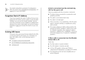
... to access the Web interface, you logged in good condition. ■ The SFP module is correctly inserted. ■ A 3Com SFP module is being connected to the following topics in Chapter 1: ■ (2) Gigabit Combo Ports (RJ-45/SFP) ■ (4) 10/100BASE-TX Link/Activity Status LEDs ■ (7) Power LED A link is connected, but the Module Active LED is a problem with this connection. See "Automatic IP Configuration" on the front panel of the Switch. There is off . A fiber cable is connected...
... to access the Web interface, you logged in good condition. ■ The SFP module is correctly inserted. ■ A 3Com SFP module is being connected to the following topics in Chapter 1: ■ (2) Gigabit Combo Ports (RJ-45/SFP) ■ (4) 10/100BASE-TX Link/Activity Status LEDs ■ (7) Power LED A link is connected, but the Module Active LED is a problem with this connection. See "Automatic IP Configuration" on the front panel of the Switch. There is off . A fiber cable is connected...
User Guide
Page 80
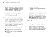
... technical support and repair services. If your original product. To access these services for a user name and password. 80 APPENDIX A: OBTAINING SUPPORT FOR YOUR PRODUCT Updates you must first register your region, use of support telephone numbers posted on the 3Com Web site at http://csoweb4.3com.com/contactus/ First time users will need to apply for assistance, please have the following information ready: ■ Product model name, part number, and serial number...
... technical support and repair services. If your original product. To access these services for a user name and password. 80 APPENDIX A: OBTAINING SUPPORT FOR YOUR PRODUCT Updates you must first register your region, use of support telephone numbers posted on the 3Com Web site at http://csoweb4.3com.com/contactus/ First time users will need to apply for assistance, please have the following information ready: ■ Product model name, part number, and serial number...

User Guide
Page 91
.... 4 Set Flow Control to none. 5 Under Properties, select VT100 for Emulation mode. 6 Select Terminal keys for Terminal keys (not Windows keys). Getting Started with the Command Line Interface Using the CLI, network managers enter configuration commands and parameters to the CLI Interface: 1 Press Enter without typing in a username. To logon to configure the device. Logging on a UNIX system. The Password prompt displays: Password: The Login information is admin. Ensure that the setting is managed through the CLI from a direct connection to the CLI The Login...
.... 4 Set Flow Control to none. 5 Under Properties, select VT100 for Emulation mode. 6 Select Terminal keys for Terminal keys (not Windows keys). Getting Started with the Command Line Interface Using the CLI, network managers enter configuration commands and parameters to the CLI Interface: 1 Press Enter without typing in a username. To logon to configure the device. Logging on a UNIX system. The Password prompt displays: Password: The Login information is admin. Ensure that the setting is managed through the CLI from a direct connection to the CLI The Login...
User Guide
Page 108
... 104 S server defined 105 SFP transceivers approved (supported) 22 inserting 22 removing 23 spot checks 23 subnet mask 105 Switch positioning 18 switch defined 105 T TCP/IP 103 defined 105 technical specifications 83 traffic 105 monitoring 66, 70 troubleshooting 75 LED-related issues 76 POST failed 21 trunking See link aggregation U user name default 40 V viewing status information 35 VLANs 44 creating 51 maximum supported 45 sample configurations 49 W Web interface accessing using the CLI 25 buttons 31 connecting 25 logging on...
... 104 S server defined 105 SFP transceivers approved (supported) 22 inserting 22 removing 23 spot checks 23 subnet mask 105 Switch positioning 18 switch defined 105 T TCP/IP 103 defined 105 technical specifications 83 traffic 105 monitoring 66, 70 troubleshooting 75 LED-related issues 76 POST failed 21 trunking See link aggregation U user name default 40 V viewing status information 35 VLANs 44 creating 51 maximum supported 45 sample configurations 49 W Web interface accessing using the CLI 25 buttons 31 connecting 25 logging on...

