Owner's Manual
Page 5
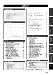
...a digital airwave tuner 20 Connecting other external components 21 Connecting a subwoofer 22 Connecting the power supply cable 23 About the RS-232C/REMOTE IN/IR-OUT terminals 23 SETUP GETTING STARTED 24 Installing batteries in the remote control 24 Operation range of the remote control 24 Using the remote control... programs 54 Adjusting CINEMA DSP effect levels 54 USING THE VOLUME MODE (Night listening mode/TV volume equal mode 55 USING BASS SOUND ENHANCER (TruBass 57 USING THE SLEEP TIMER 58 Setting the sleep timer 58 Canceling the sleep timer 59 ADVANCED OPERATION MANUAL SETUP ...
...a digital airwave tuner 20 Connecting other external components 21 Connecting a subwoofer 22 Connecting the power supply cable 23 About the RS-232C/REMOTE IN/IR-OUT terminals 23 SETUP GETTING STARTED 24 Installing batteries in the remote control 24 Operation range of the remote control 24 Using the remote control... programs 54 Adjusting CINEMA DSP effect levels 54 USING THE VOLUME MODE (Night listening mode/TV volume equal mode 55 USING BASS SOUND ENHANCER (TruBass 57 USING THE SLEEP TIMER 58 Setting the sleep timer 58 Canceling the sleep timer 59 ADVANCED OPERATION MANUAL SETUP ...
Owner's Manual
Page 7
...remote control codes to be used to control the DVD player, VCR, cable TV tuner and digital satellite tuner connected to this improved technology provides an exceptionally stable sound field that you can avoid troublesome listening-based speaker setup and achieve highly accurate sound... " " logo and "Digital Sound Projector™" are trademarks of Dolby Pro Logic that you can adjust the beam angle manually or automatically using the supplied remote control. Cinema DSP Digital This unit employs the Cinema DSP Digital technology developed by YAMAHA Electronics Corp. This surround...
...remote control codes to be used to control the DVD player, VCR, cable TV tuner and digital satellite tuner connected to this improved technology provides an exceptionally stable sound field that you can avoid troublesome listening-based speaker setup and achieve highly accurate sound... " " logo and "Digital Sound Projector™" are trademarks of Dolby Pro Logic that you can adjust the beam angle manually or automatically using the supplied remote control. Cinema DSP Digital This unit employs the Cinema DSP Digital technology developed by YAMAHA Electronics Corp. This surround...
Owner's Manual
Page 8
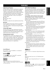
...describes how to fine-tune settings and/or set remote control codes. See "PLAYBACK" on page 42. See "ENJOYING SURROUND SOUND" on page 39. 6 Change the beam modes and/or CINEMA DSP settings. See "CONNECTIONS" on page 15. 3 Prepare the remote control and turn on page 11. 2 Connect...In such cases, the operation is printed prior to the supplied owner's manual for the component. • Some operations can be performed by using remote control operation. • y indicates a tip for your TV and other external components. See "INSTALLATION" on the power of differences between the ...
...describes how to fine-tune settings and/or set remote control codes. See "PLAYBACK" on page 42. See "ENJOYING SURROUND SOUND" on page 39. 6 Change the beam modes and/or CINEMA DSP settings. See "CONNECTIONS" on page 15. 3 Prepare the remote control and turn on page 11. 2 Connect...In such cases, the operation is printed prior to the supplied owner's manual for the component. • Some operations can be performed by using remote control operation. • y indicates a tip for your TV and other external components. See "INSTALLATION" on the power of differences between the ...
Owner's Manual
Page 9
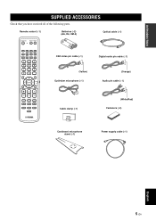
INTRODUCTION SUPPLIED ACCESSORIES SUPPLIED ACCESSORIES Check that you have received all of the following parts. Remote control (×1) Batteries (×2) (AA, R6, UM-3) Optical cable (×1) STANDBY/ON POWER POWER AV TV STB VCR DVD AUX TV ...SLEEP 5BEAM 1 ST+3BEAM 2 3BEAM 3 STEREO 4 MY BEAM SURROUND 5 6 MUSIC 7 MOVIE 8 SPORTS 9 OFF 0 +10 CH LEVEL MENU TEST ENTER TV/AV YSP RETURN VOLUME CH TV VOL OSD video pin cable (×1) Digital audio pin cable (×1) (Yellow) Optimizer microphone (×1) (Orange) Audio pin cable (×1) MUTE TV INPUT TV MUTE...
INTRODUCTION SUPPLIED ACCESSORIES SUPPLIED ACCESSORIES Check that you have received all of the following parts. Remote control (×1) Batteries (×2) (AA, R6, UM-3) Optical cable (×1) STANDBY/ON POWER POWER AV TV STB VCR DVD AUX TV ...SLEEP 5BEAM 1 ST+3BEAM 2 3BEAM 3 STEREO 4 MY BEAM SURROUND 5 6 MUSIC 7 MOVIE 8 SPORTS 9 OFF 0 +10 CH LEVEL MENU TEST ENTER TV/AV YSP RETURN VOLUME CH TV VOL OSD video pin cable (×1) Digital audio pin cable (×1) (Yellow) Optimizer microphone (×1) (Orange) Audio pin cable (×1) MUTE TV INPUT TV MUTE...
Owner's Manual
Page 10
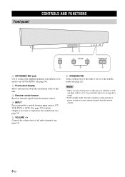
...• When you turn on the power of this unit or sets it can reproduce sound. • In the standby mode, this unit consumes a small amount of power in order to receive infrared-signals from the remote control. 4 INPUT Press repeatedly to switch between input sources (TV, VCR, DVD or... AUX). Outputs a test tone to experience the sound beam (see page 72). 5 VOLUME -/+ Controls the volume level of all audio ...
...• When you turn on the power of this unit or sets it can reproduce sound. • In the standby mode, this unit consumes a small amount of power in order to receive infrared-signals from the remote control. 4 INPUT Press repeatedly to switch between input sources (TV, VCR, DVD or... AUX). Outputs a test tone to experience the sound beam (see page 72). 5 VOLUME -/+ Controls the volume level of all audio ...
Owner's Manual
Page 12
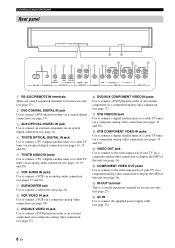
...D 1 2 34 5 6 7 89 A C COMPONENT COMPONENT COMPONENT DVD COAXIAL AUX TV/STB OPTICAL TV/STB VCR VCR DVD/AUX STB RS-232C REMOTE IN DIGITAL IN AUDIO IN SUBWOOFER VIDEO IN VIDEO OUT 1 RS-232C/REMOTE IN terminals These are control expansion terminals for factory use only (see page 23). 2 DVD COAXIAL... DIGITAL IN jack Use to connect a DVD player/recorder via a coaxial digital connection (see page 17). 3 AUX OPTICAL DIGITAL IN jack Use to connect ...
...D 1 2 34 5 6 7 89 A C COMPONENT COMPONENT COMPONENT DVD COAXIAL AUX TV/STB OPTICAL TV/STB VCR VCR DVD/AUX STB RS-232C REMOTE IN DIGITAL IN AUDIO IN SUBWOOFER VIDEO IN VIDEO OUT 1 RS-232C/REMOTE IN terminals These are control expansion terminals for factory use only (see page 23). 2 DVD COAXIAL... DIGITAL IN jack Use to connect a DVD player/recorder via a coaxial digital connection (see page 17). 3 AUX OPTICAL DIGITAL IN jack Use to connect ...
Owner's Manual
Page 13
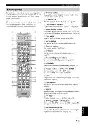
... SLEEP 5BEAM ST+3BEAM 3BEAM 1 2 3 STEREO MY BEAM SURROUND 4 5 6 MUSIC 7 MOVIE 8 SPORTS 9 OFF 0 +10 CH LEVEL MENU TEST ENTER TV/AV YSP RETURN VOLUME CH TV VOL MUTE TV INPUT TV MUTE CODE SET 1 Infrared window Outputs infrared control signals. Aim this unit. Use to change... program buttons Use to select sound field programs (see page 50). 0 CH LEVEL Adjusts the volume level of each speaker (see page 72). English 9 En G My beam microphone Use to collect the test tones from this unit when using the remote control once you want to operate. 2 STANDBY...
... SLEEP 5BEAM ST+3BEAM 3BEAM 1 2 3 STEREO MY BEAM SURROUND 4 5 6 MUSIC 7 MOVIE 8 SPORTS 9 OFF 0 +10 CH LEVEL MENU TEST ENTER TV/AV YSP RETURN VOLUME CH TV VOL MUTE TV INPUT TV MUTE CODE SET 1 Infrared window Outputs infrared control signals. Aim this unit. Use to change... program buttons Use to select sound field programs (see page 50). 0 CH LEVEL Adjusts the volume level of each speaker (see page 72). English 9 En G My beam microphone Use to collect the test tones from this unit when using the remote control once you want to operate. 2 STANDBY...
Owner's Manual
Page 14
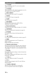
P MY BEAM Use to set up the appropriate remote control codes. V CH +/- Use to select the my beam as the beam mode (see page 81). 10 En ...the power of the TV or sets it to the previous SET MENU screen. K MACRO Use to effectively reproduce the bass sound (see page 82). L SLEEP Sets the sleep timer (see pages 42, 47 and 48). W TV MUTE, CODE ... TV (see page 57). Q TruBass Use to set up remote control codes (see page 48). I AV POWER Turns on your TV monitor (see pages 82 and 83). Select YSP when operating this unit. Adjusts the volume level of the TV...
P MY BEAM Use to set up the appropriate remote control codes. V CH +/- Use to select the my beam as the beam mode (see page 81). 10 En ...the power of the TV or sets it to the previous SET MENU screen. K MACRO Use to effectively reproduce the bass sound (see page 82). L SLEEP Sets the sleep timer (see pages 42, 47 and 48). W TV MUTE, CODE ... TV (see page 57). Q TruBass Use to set up remote control codes (see page 48). I AV POWER Turns on your TV monitor (see pages 82 and 83). Select YSP when operating this unit. Adjusts the volume level of the TV...
Owner's Manual
Page 20
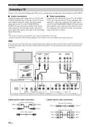
.../STB AUDIO IN jacks of this unit COMPONENT COMPONENT COMPONENT DVD COAXIAL AUX TV/STB OPTICAL TV/STB VCR VCR DVD/AUX STB RS-232C REMOTE IN DIGITAL IN AUDIO IN SUBWOOFER VIDEO IN VIDEO OUT Cables used for audio connections (White) Audio pin cable (supplied) (White) (Red) Optical ...the system parameters in addition to the analog audio connection. your TV to the COMPONENT VIDEO OUT jacks of this unit. TV Optical digital output Analog audio output RL Video input Component video input Remove the caps if attached Check the direction Rear panel of this unit....
.../STB AUDIO IN jacks of this unit COMPONENT COMPONENT COMPONENT DVD COAXIAL AUX TV/STB OPTICAL TV/STB VCR VCR DVD/AUX STB RS-232C REMOTE IN DIGITAL IN AUDIO IN SUBWOOFER VIDEO IN VIDEO OUT Cables used for audio connections (White) Audio pin cable (supplied) (White) (Red) Optical ...the system parameters in addition to the analog audio connection. your TV to the COMPONENT VIDEO OUT jacks of this unit. TV Optical digital output Analog audio output RL Video input Component video input Remove the caps if attached Check the direction Rear panel of this unit....

Owner's Manual
Page 21
...your DVD player/recorder. COMPONENT COMPONENT COMPONENT DVD COAXIAL AUX TV/STB OPTICAL TV/STB VCR VCR DVD/AUX STB RS-232C REMOTE IN DIGITAL IN AUDIO IN SUBWOOFER VIDEO IN VIDEO OUT Cables used for audio connections (White) Audio pin cable (White) (Red) (Red...cable (Green) (Blue) (Red) English 17 En For details, refer to the operation manual supplied with better resolution. DVD player/recorder Coaxial digital Analog audio output output RL Video output Component video input Note * In case you connect this unit to a DVD/VCR combo player/recorder Rear ...
...your DVD player/recorder. COMPONENT COMPONENT COMPONENT DVD COAXIAL AUX TV/STB OPTICAL TV/STB VCR VCR DVD/AUX STB RS-232C REMOTE IN DIGITAL IN AUDIO IN SUBWOOFER VIDEO IN VIDEO OUT Cables used for audio connections (White) Audio pin cable (White) (Red) (Red...cable (Green) (Blue) (Red) English 17 En For details, refer to the operation manual supplied with better resolution. DVD player/recorder Coaxial digital Analog audio output output RL Video output Component video input Note * In case you connect this unit to a DVD/VCR combo player/recorder Rear ...
Owner's Manual
Page 22
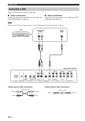
... left and right input jacks of this unit COMPONENT COMPONENT DVD COAXIAL AUX TV/STB OPTICAL TV/STB VCR VCR DVD/AUX STB RS-232C REMOTE IN DIGITAL IN AUDIO IN SUBWOOFER VIDEO IN VIDEO OUT Cables used for audio connections (White) Audio pin cable (White) (Red) (Red) Cables used for video...
... left and right input jacks of this unit COMPONENT COMPONENT DVD COAXIAL AUX TV/STB OPTICAL TV/STB VCR VCR DVD/AUX STB RS-232C REMOTE IN DIGITAL IN AUDIO IN SUBWOOFER VIDEO IN VIDEO OUT Cables used for audio connections (White) Audio pin cable (White) (Red) (Red) Cables used for video...
Owner's Manual
Page 23
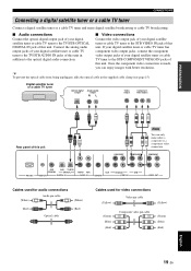
COMPONENT DVD COAXIAL AUX TV/STB OPTICAL TV/STB VCR VCR DVD/AUX STB RS-232C REMOTE IN DIGITAL IN AUDIO IN SUBWOOFER VIDEO IN VIDEO OUT Cables used for audio connections (White) Audio pin cable (White) (Red) Optical cable (Red) Cables used for .... Once the component video connection is made, you can only make either a composite or a component video connection. Connect the analog audio output jacks of your digital satellite tuner or cable TV tuner to the TV/STB AUDIO IN jacks of this unit in the supplied cable clamp (see page 15...
COMPONENT DVD COAXIAL AUX TV/STB OPTICAL TV/STB VCR VCR DVD/AUX STB RS-232C REMOTE IN DIGITAL IN AUDIO IN SUBWOOFER VIDEO IN VIDEO OUT Cables used for audio connections (White) Audio pin cable (White) (Red) Optical cable (Red) Cables used for .... Once the component video connection is made, you can only make either a composite or a component video connection. Connect the analog audio output jacks of your digital satellite tuner or cable TV tuner to the TV/STB AUDIO IN jacks of this unit in the supplied cable clamp (see page 15...
Owner's Manual
Page 24
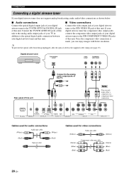
... jack of this unit. COMPONENT DVD COAXIAL AUX TV/STB OPTICAL TV/STB VCR VCR DVD/AUX STB RS-232C REMOTE IN DIGITAL IN AUDIO IN SUBWOOFER VIDEO IN VIDEO OUT Cables used for audio connections (White) Audio pin cable (White) (Red) Optical cable (Red) Cables... Once the component video connection is made, you can only make audio/video connections as shown below. ■ Audio connections Connect the optical digital output jack of your digital airwave tuner to the STB VIDEO IN jack of this unit. COMPONENT COMPONENT Note You can enjoy images with better resolution...
... jack of this unit. COMPONENT DVD COAXIAL AUX TV/STB OPTICAL TV/STB VCR VCR DVD/AUX STB RS-232C REMOTE IN DIGITAL IN AUDIO IN SUBWOOFER VIDEO IN VIDEO OUT Cables used for audio connections (White) Audio pin cable (White) (Red) Optical cable (Red) Cables... Once the component video connection is made, you can only make audio/video connections as shown below. ■ Audio connections Connect the optical digital output jack of your digital airwave tuner to the STB VIDEO IN jack of this unit. COMPONENT COMPONENT Note You can enjoy images with better resolution...
Owner's Manual
Page 25
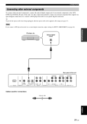
... cable in the supplied cable clamp (see page 68). CD player, etc. Optical digital output PREPARATION COMPONENT Rear panel of this unit COMPONENT COMPONENT RS-232C DVD COAXIAL AUX TV/STB OPTICAL REMOTE IN DIGITAL IN TV/STB VCR AUDIO IN VCR SUBWOOFER DVD/AUX STB VIDEO IN VIDEO OUT... Cables used for INPUT ASSIGNMENT (see page 15). Note If you connect a DVD player/recorder via an optical digital connection. Use this connection method to ...
... cable in the supplied cable clamp (see page 68). CD player, etc. Optical digital output PREPARATION COMPONENT Rear panel of this unit COMPONENT COMPONENT RS-232C DVD COAXIAL AUX TV/STB OPTICAL REMOTE IN DIGITAL IN TV/STB VCR AUDIO IN VCR SUBWOOFER DVD/AUX STB VIDEO IN VIDEO OUT... Cables used for INPUT ASSIGNMENT (see page 15). Note If you connect a DVD player/recorder via an optical digital connection. Use this connection method to ...
Owner's Manual
Page 26
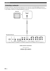
... 22 En If a subwoofer is connected to the SUBWOOFER jack of this unit COMPONENT COMPONENT COMPONENT RS-232C DVD COAXIAL AUX TV/STB OPTICAL REMOTE IN DIGITAL IN TV/STB VCR AUDIO IN VCR SUBWOOFER DVD/AUX STB VIDEO IN VIDEO OUT Cables used for BASS OUT in SUBWOOFER SET (see page...
... 22 En If a subwoofer is connected to the SUBWOOFER jack of this unit COMPONENT COMPONENT COMPONENT RS-232C DVD COAXIAL AUX TV/STB OPTICAL REMOTE IN DIGITAL IN TV/STB VCR AUDIO IN VCR SUBWOOFER DVD/AUX STB VIDEO IN VIDEO OUT Cables used for BASS OUT in SUBWOOFER SET (see page...
Owner's Manual
Page 27
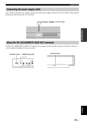
... terminal of this unit and then plug the other connections are control expansion terminals for factory use only. RS-232C terminal REMOTE IN terminal IR-OUT terminal RS-232C AUX COAXIAL DVD TV/STB OPTICAL REMOTE IN DIGITAL INPUT TV/STB AUDIO English 23 En To the AC outlet About the RS-232C...
... terminal of this unit and then plug the other connections are control expansion terminals for factory use only. RS-232C terminal REMOTE IN terminal IR-OUT terminal RS-232C AUX COAXIAL DVD TV/STB OPTICAL REMOTE IN DIGITAL INPUT TV/STB AUDIO English 23 En To the AC outlet About the RS-232C...
Owner's Manual
Page 28
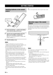
...If this happens, replace the batteries with two new ones as soon as these different types of batteries may have leaked, dispose of the remote control decreases considerably. Press 1 Press and hold the mark on this unit during operation. 2 Insert the two supplied batteries (AA, R6... contact with general house waste. If the batteries have the same shape and color. • Exhausted batteries may be erased in the remote control may leak. places of high temperatures, such as inverted fluorescent lamps. • If the batteries grow old, the effective operation distance...
...If this happens, replace the batteries with two new ones as soon as these different types of batteries may have leaked, dispose of the remote control decreases considerably. Press 1 Press and hold the mark on this unit during operation. 2 Insert the two supplied batteries (AA, R6... contact with general house waste. If the batteries have the same shape and color. • Exhausted batteries may be erased in the remote control may leak. places of high temperatures, such as inverted fluorescent lamps. • If the batteries grow old, the effective operation distance...
Owner's Manual
Page 29
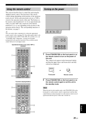
... MENU TEST ENTER TV/AV YSP RETURN VOLUME CH TV VOL 8 9 Turning on the power INPUT VOLUME + STANDBY/ON STANDBY/ON POWER POWER AV TV STB VCR DVD AUX TV INPUT1 INPUT2 MACRO TV 1 Press STANDBY/ON on the front panel or on the remote control to 4 are operational only when you select... YSP. The volume level appears in the...
... MENU TEST ENTER TV/AV YSP RETURN VOLUME CH TV VOL 8 9 Turning on the power INPUT VOLUME + STANDBY/ON STANDBY/ON POWER POWER AV TV STB VCR DVD AUX TV INPUT1 INPUT2 MACRO TV 1 Press STANDBY/ON on the front panel or on the remote control to 4 are operational only when you select... YSP. The volume level appears in the...
Owner's Manual
Page 30
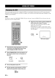
... of this unit. TV TV AUTO:ANALOG OSD screen example TEST ENTER TV/AV YSP RETURN 1 Check that the video input jack on your own home. Once this is complete, you can enjoy real surround sound while watching TV in the comfort of your TV is not output at the COMPONENT...INPUTMODE SLEEP 5BEAM ST+3BEAM 3BEAM 1 2 3 STEREO MY BEAM SURROUND 4 5 6 MUSIC 7 MOVIE 8 SPORTS 9 OFF 0 +10 CH LEVEL MENU 5 Press TV on the remote control to display the OSD of this unit on your listening room. TV/AV YSP 26 En USING SET MENU USING SET MENU Displaying the OSD This section simply describes...
... of this unit. TV TV AUTO:ANALOG OSD screen example TEST ENTER TV/AV YSP RETURN 1 Check that the video input jack on your own home. Once this is complete, you can enjoy real surround sound while watching TV in the comfort of your TV is not output at the COMPONENT...INPUTMODE SLEEP 5BEAM ST+3BEAM 3BEAM 1 2 3 STEREO MY BEAM SURROUND 4 5 6 MUSIC 7 MOVIE 8 SPORTS 9 OFF 0 +10 CH LEVEL MENU 5 Press TV on the remote control to display the OSD of this unit on your listening room. TV/AV YSP 26 En USING SET MENU USING SET MENU Displaying the OSD This section simply describes...
Owner's Manual
Page 32
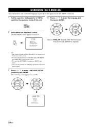
...used for SET MENU are displayed on the bottom of this unit. 4 Press / to the previous screen while using SET MENU, press RETURN on the remote control. • To cancel the SET MENU screen, press MENU once more. • You can also perform the following screen appears on your TV.... ENTER ENTER p p p p LANGUAGE SETUP . TV/AV YSP 2 Press MENU on your TV. The SET MENU screen appears on the remote control. ENGLISH DEUTSCH Francais ESPANOL [ ]/[ ]:Select [ENTER]:Return 28 En
...used for SET MENU are displayed on the bottom of this unit. 4 Press / to the previous screen while using SET MENU, press RETURN on the remote control. • To cancel the SET MENU screen, press MENU once more. • You can also perform the following screen appears on your TV.... ENTER ENTER p p p p LANGUAGE SETUP . TV/AV YSP 2 Press MENU on your TV. The SET MENU screen appears on the remote control. ENGLISH DEUTSCH Francais ESPANOL [ ]/[ ]:Select [ENTER]:Return 28 En


