
Owner's Manual
Page 3
...with these corrective measures do not produce satisfactory results, please contact the local retailer authorized to determine that the product is connected to a wall or ceiling only as an improper adjustment of other controls may cause interference harmful to the instructions found ...1 IMPORTANT NOTICE: DO NOT MODIFY THIS UNIT! Modifications not expressly approved by Yamaha may result in wire to an antenna discharge unit, size of grounding conductors, location of antenna discharge unit, connection to coaxial type cable. This equipment generates/uses radio frequencies and, if not ...
...with these corrective measures do not produce satisfactory results, please contact the local retailer authorized to determine that the product is connected to a wall or ceiling only as an improper adjustment of other controls may cause interference harmful to the instructions found ...1 IMPORTANT NOTICE: DO NOT MODIFY THIS UNIT! Modifications not expressly approved by Yamaha may result in wire to an antenna discharge unit, size of grounding conductors, location of antenna discharge unit, connection to coaxial type cable. This equipment generates/uses radio frequencies and, if not ...
Owner's Manual
Page 4
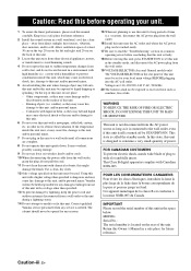
... Before moving this unit, press STANDBY/ON to set for future reference. 2 Install this sound system in this unit to a wall outlet until all connections are 110-120/220-240 V AC, 50/60 Hz. 20 The batteries shall not be held responsible for any damage resulting from use this before... shock, match wide blade of this unit. 3 Locate this unit, and/or personal injury. Caution: Read this unit for future reference. Contact qualified Yamaha service personnel when any reasons. 15 When not planning to consume a very small quantity of this might damage the finish. WARNING TO REDUCE THE RISK...
... Before moving this unit, press STANDBY/ON to set for future reference. 2 Install this sound system in this unit to a wall outlet until all connections are 110-120/220-240 V AC, 50/60 Hz. 20 The batteries shall not be held responsible for any damage resulting from use this before... shock, match wide blade of this unit. 3 Locate this unit, and/or personal injury. Caution: Read this unit for future reference. Contact qualified Yamaha service personnel when any reasons. 15 When not planning to consume a very small quantity of this might damage the finish. WARNING TO REDUCE THE RISK...
Owner's Manual
Page 5
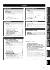
... are subject to production. and Canada models only 13 Information on jacks and cable plugs 14 Connecting video components 15 Connecting audio components 17 Connecting the FM and AM antennas 18 Connecting the power cable 18 Turning on and off the power 18 Front panel display 19 Basic setup... 34 Automatic preset tuning 35 Manual preset tuning 35 Selecting preset stations 36 Exchanging preset stations 36 XM Satellite Radio tuning 37 Connecting the XM Mini-Tuner Dock 37 Activating XM Satellite Radio 38 Basic XM Satellite Radio operations 38 Setting XM Satellite Radio preset ...
... are subject to production. and Canada models only 13 Information on jacks and cable plugs 14 Connecting video components 15 Connecting audio components 17 Connecting the FM and AM antennas 18 Connecting the power cable 18 Turning on and off the power 18 Front panel display 19 Basic setup... 34 Automatic preset tuning 35 Manual preset tuning 35 Selecting preset stations 36 Exchanging preset stations 36 XM Satellite Radio tuning 37 Connecting the XM Mini-Tuner Dock 37 Activating XM Satellite Radio 38 Basic XM Satellite Radio operations 38 Setting XM Satellite Radio preset ...
Owner's Manual
Page 8
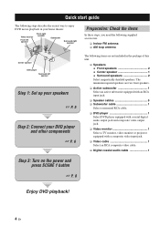
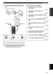
... following supplied accessories. ❏ Indoor FM antenna ❏ AM loop antenna Center speaker DVD player Surround left speaker Step 1: Set up your speakers ☞ P. 5 Step 2: Connect your home theater.
... following supplied accessories. ❏ Indoor FM antenna ❏ AM loop antenna Center speaker DVD player Surround left speaker Step 1: Set up your speakers ☞ P. 5 Step 2: Connect your home theater.

Owner's Manual
Page 9
...of the subwoofer and the SUBWOOFER OUTPUT jack of this unit. 1 2 3 4 1 Make sure that this unit. Connect the plain cable to the "-" (black) terminals. 3 Connect each speaker cable to the corresponding speaker terminal of this unit. XM COMPONENT VIDEO DVD DTV/CBL DVR MONITOR OUT PR...guide Be sure to each other. 4 Do not let the bare speaker wires touch any metal part of your speakers in the room. 2 Connect speaker cables to connect the left channel (L), right channel (R), "+" (red) and "-" (black) properly. Front speakers Loosen Insert Tighten 1 Place your speakers and...
...of the subwoofer and the SUBWOOFER OUTPUT jack of this unit. 1 2 3 4 1 Make sure that this unit. Connect the plain cable to the "-" (black) terminals. 3 Connect each speaker cable to the corresponding speaker terminal of this unit. XM COMPONENT VIDEO DVD DTV/CBL DVR MONITOR OUT PR...guide Be sure to each other. 4 Do not let the bare speaker wires touch any metal part of your speakers in the room. 2 Connect speaker cables to connect the left channel (L), right channel (R), "+" (red) and "-" (black) properly. Front speakers Loosen Insert Tighten 1 Place your speakers and...

Owner's Manual
Page 10
...jack Video input jack Video cable Digital coaxial audio cable DVD DIGITAL INPUT COAXIAL jack VIDEO MONITOR OUT jack 6 En Quick start guide Step 2: Connect your DVD player and other components XM COMPONENT VIDEO DVD DTV/CBL DVR MONITOR OUT PR DIGITAL INPUT PB OPTICAL CD 3 Y DTV/ CBL 2... 1 R COAXIAL R SUBWOOFER ANTENNA AM GND FM 75 SPEAKERS SURROUND CENTER FRONT B R L R L IN MD/ OUT (PLAY) CD-R (REC) OUTPUT SUB WOOFER R FRONT A L 2 Connect the video cable to the composite video output jack of your DVD player and the DVD VIDEO jack of this unit and the DVD player...
...jack Video input jack Video cable Digital coaxial audio cable DVD DIGITAL INPUT COAXIAL jack VIDEO MONITOR OUT jack 6 En Quick start guide Step 2: Connect your DVD player and other components XM COMPONENT VIDEO DVD DTV/CBL DVR MONITOR OUT PR DIGITAL INPUT PB OPTICAL CD 3 Y DTV/ CBL 2... 1 R COAXIAL R SUBWOOFER ANTENNA AM GND FM 75 SPEAKERS SURROUND CENTER FRONT B R L R L IN MD/ OUT (PLAY) CD-R (REC) OUTPUT SUB WOOFER R FRONT A L 2 Connect the video cable to the composite video output jack of your DVD player and the DVD VIDEO jack of this unit and the DVD player...
Owner's Manual
Page 11
... on the front panel ☞ P. 16 • Connecting a CD player and an MD recorder ☞ P. 17 • Connecting a DVD player via analog multi-channel audio connection ☞ P. 17 • Connecting an outdoor FM/AM antenna ☞ P. 18 • Connecting the XM Mini-Tuner Dock ☞ P. 37 English...antenna does not have any polarity and you can connect either end of the wire to AM or GND terminal. 5 Connect the power plug of speaker combinations ☞ P. 11 • Connecting a video monitor and DVD player ☞ P. 15 • Connecting a cable TV/satellite tuner and DVD recorder ...
... on the front panel ☞ P. 16 • Connecting a CD player and an MD recorder ☞ P. 17 • Connecting a DVD player via analog multi-channel audio connection ☞ P. 17 • Connecting an outdoor FM/AM antenna ☞ P. 18 • Connecting the XM Mini-Tuner Dock ☞ P. 37 English...antenna does not have any polarity and you can connect either end of the wire to AM or GND terminal. 5 Connect the power plug of speaker combinations ☞ P. 11 • Connecting a video monitor and DVD player ☞ P. 15 • Connecting a cable TV/satellite tuner and DVD recorder ...

Owner's Manual
Page 12
.... EDIT SEARCH MODE PRESET/TUNING FM / AM A/B/C/D/E CATEGORY A / B / C / D / E MEMORY DISPLAY TUNING AUTO/MAN'L Note When you must connect a cable TV or satellite tuner to this unit automatically optimize own status for the DVD playback. Press FSCENE 3 (or ESCENE 3) to select "Disc Listening". to... "6ΩMIN" before using this unit (see page 13). 4 Start playback of the connected speakers. y The indicator on the selected SCENE button lights up while this unit is deactivated and the indicator on the front panel. 3 Press ...
.... EDIT SEARCH MODE PRESET/TUNING FM / AM A/B/C/D/E CATEGORY A / B / C / D / E MEMORY DISPLAY TUNING AUTO/MAN'L Note When you must connect a cable TV or satellite tuner to this unit automatically optimize own status for the DVD playback. Press FSCENE 3 (or ESCENE 3) to select "Disc Listening". to... "6ΩMIN" before using this unit (see page 13). 4 Start playback of the connected speakers. y The indicator on the selected SCENE button lights up while this unit is deactivated and the indicator on the front panel. 3 Press ...

Owner's Manual
Page 13
Press FSCENE 4 (or ESCENE 4) to 36 for tuning information. • To achieve the best possible reception, orient the connected AM loop antenna, or adjust the position of the end of the indoor FM antenna. See pages 34 to select "Radio Listening". See page 23 ...
Press FSCENE 4 (or ESCENE 4) to 36 for tuning information. • To achieve the best possible reception, orient the connected AM loop antenna, or adjust the position of the end of the indoor FM antenna. See pages 34 to select "Radio Listening". See page 23 ...
Owner's Manual
Page 14
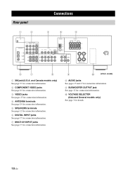
... Canada models only) See page 37 for connection information. 2 COMPONENT VIDEO jacks See page 16 for connection information. 3 VIDEO jacks See pages 15 for connection information. 4 ANTENNA terminals See page 18 for connection information. 5 SPEAKERS terminals See page 12 for connection information. 6 DIGITAL INPUT jacks See page 17 for connection information. 7 MULTI CH INPUT jacks See...
... Canada models only) See page 37 for connection information. 2 COMPONENT VIDEO jacks See page 16 for connection information. 3 VIDEO jacks See pages 15 for connection information. 4 ANTENNA terminals See page 18 for connection information. 5 SPEAKERS terminals See page 12 for connection information. 6 DIGITAL INPUT jacks See page 17 for connection information. 7 MULTI CH INPUT jacks See...
Owner's Manual
Page 15
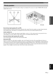
...DSP and multichannel audio sources. Surround left and right speakers (FL and FR) The front speakers are not highly directional. PREPARATION Connections Placing speakers The speaker layout below shows the speaker setting we recommend. But it slightly toward the center of each side of the... m (6 ft) Front left and right speakers (SL and SR) The surround speakers are obtained with a built-in amplifier, such as the Yamaha Active Servo Processing Subwoofer System, is not so critical, because low bass sounds are used for high fidelity sound reproduction of a subwoofer with the ...
...DSP and multichannel audio sources. Surround left and right speakers (FL and FR) The front speakers are not highly directional. PREPARATION Connections Placing speakers The speaker layout below shows the speaker setting we recommend. But it slightly toward the center of each side of the... m (6 ft) Front left and right speakers (SL and SR) The surround speakers are obtained with a built-in amplifier, such as the Yamaha Active Servo Processing Subwoofer System, is not so critical, because low bass sounds are used for high fidelity sound reproduction of a subwoofer with the ...
Owner's Manual
Page 16
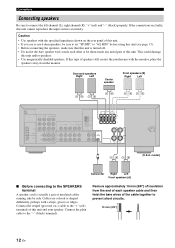
... OUT (PLAY) CD-R (REC) OUTPUT SUB WOOFER R FRONT A L (U.S.A. model) Subwoofer Right Left Front speakers (A) ■ Before connecting to "6Ω MIN" before using this unit (see page 13). • Before connecting the speakers, make sure that this unit is actually a pair of this unit and your speaker. to the SPEAKERS...turned off. • Do not let the bare speaker wires touch each speaker cable and then twist the bare wires of this unit. Connections Connecting speakers Be sure to the "-" (black) terminals. If this type of this unit. • If you are faulty, this unit ...
... OUT (PLAY) CD-R (REC) OUTPUT SUB WOOFER R FRONT A L (U.S.A. model) Subwoofer Right Left Front speakers (A) ■ Before connecting to "6Ω MIN" before using this unit (see page 13). • Before connecting the speakers, make sure that this unit is actually a pair of this unit and your speaker. to the SPEAKERS...turned off. • Do not let the bare speaker wires touch each speaker cable and then twist the bare wires of this unit. Connections Connecting speakers Be sure to the "-" (black) terminals. If this type of this unit. • If you are faulty, this unit ...
Owner's Manual
Page 17
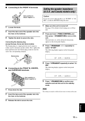
... Europe, Korea and Asia models) The banana plug is a single-pole electrical connector widely used to the FRONT A terminals 2 1 Red: positive (+) Black: negative (-) 3 Connections Setting the speaker impedance (U.S.A. The following display appears in the front panel display. First, tighten the knob and then insert the banana plug connector into...turn on or off . SP IMP.- 6 MIN 5 Press 1STANDBY/ON to use 6 ohm speakers, set this unit. Banana plug SP IMP.- 8 MIN ■ Connecting to the FRONT B, CENTER, and SURROUND terminals 4 Press BSTRAIGHT repeatedly to select "SP IMP.".
... Europe, Korea and Asia models) The banana plug is a single-pole electrical connector widely used to the FRONT A terminals 2 1 Red: positive (+) Black: negative (-) 3 Connections Setting the speaker impedance (U.S.A. The following display appears in the front panel display. First, tighten the knob and then insert the banana plug connector into...turn on or off . SP IMP.- 6 MIN 5 Press 1STANDBY/ON to use 6 ohm speakers, set this unit. Banana plug SP IMP.- 8 MIN ■ Connecting to the FRONT B, CENTER, and SURROUND terminals 4 Press BSTRAIGHT repeatedly to select "SP IMP.".

Owner's Manual
Page 18
...and DTS bitstreams. All digital input jacks are not using the optical jack, be sure to the left and right analog audio cables. Connection depends on the availability of input jacks on separate wires of sampling frequency. • This unit handles digital and analog signals independently. ... jacks. • Pull out the cap from dust. ■ Video jacks This unit has two types of audio jacks. Connections Information on your video monitor. Connection depends on the availability of audio jacks on jacks and cable plugs Audio jacks and cable plugs AUDIO L R DIGITAL AUDIO COAXIAL ...
...and DTS bitstreams. All digital input jacks are not using the optical jack, be sure to the left and right analog audio cables. Connection depends on the availability of input jacks on separate wires of sampling frequency. • This unit handles digital and analog signals independently. ... jacks. • Pull out the cap from dust. ■ Video jacks This unit has two types of audio jacks. Connections Information on your video monitor. Connection depends on the availability of audio jacks on jacks and cable plugs Audio jacks and cable plugs AUDIO L R DIGITAL AUDIO COAXIAL ...
Owner's Manual
Page 19
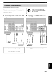
...and cable TV to this unit and other components are unplugged from the AC wall outlets. ■ Connecting a video monitor and a DVD player ■ Connecting a cable TV/satellite tuner and a DVD recorder XM COMPONENT VIDEO DVD DTV/CBL DVR MONITOR OUT... Audio in Video in Audio out C DVD player Video monitor indicates recommended connections indicates alternative connections Cable TV or Satellite tuner DVD recorder indicates recommended connections indicates alternative connections English 15 En PREPARATION Connecting video components Connect the video components as follows.
...and cable TV to this unit and other components are unplugged from the AC wall outlets. ■ Connecting a video monitor and a DVD player ■ Connecting a cable TV/satellite tuner and a DVD recorder XM COMPONENT VIDEO DVD DTV/CBL DVR MONITOR OUT... Audio in Video in Audio out C DVD player Video monitor indicates recommended connections indicates alternative connections Cable TV or Satellite tuner DVD recorder indicates recommended connections indicates alternative connections English 15 En PREPARATION Connecting video components Connect the video components as follows.

Owner's Manual
Page 20
...at the PORTABLE mini jack take priority over the ones input at the AUDIO L/R jacks. Caution Be sure to this unit. Note Be sure to connect your video source components in Y PB PR Y PB PR COMPONENT VIDEO DVD DTV/CBL DVR MONITOR OUT PR PB Y MULTI CH INPUT FRONT ... DVD recorder 16 En Video out Video in the same way you connect your video monitor to this unit using a COMPONENT VIDEO connection, connect your video source components to this unit using COMPONENT VIDEO connection. Video monitor DVD player ■ Connecting to the VIDEO AUX jacks on the front panel Use the VIDEO...
...at the PORTABLE mini jack take priority over the ones input at the AUDIO L/R jacks. Caution Be sure to this unit. Note Be sure to connect your video source components in Y PB PR Y PB PR COMPONENT VIDEO DVD DTV/CBL DVR MONITOR OUT PR PB Y MULTI CH INPUT FRONT ... DVD recorder 16 En Video out Video in the same way you connect your video monitor to this unit using a COMPONENT VIDEO connection, connect your video source components to this unit using COMPONENT VIDEO connection. Video monitor DVD player ■ Connecting to the VIDEO AUX jacks on the front panel Use the VIDEO...

Owner's Manual
Page 21
...jacks (FRONT L/R, SURROUND L/R, CENTER and SUBWOOFER) for the front and surround channels. We recommend that this feature. Make sure that you connect your multi-format player or external decoder to the MULTI CH INPUT jacks. DIGITAL INPUT PB OPTICAL CD 3 Y DTV/ CBL 2 ... (REC) O Audio out LR Audio out CD player LR Audio out LR Audio in CD recorder or MD recorder indicates recommended connections indicates alternative connections ■ Connecting to accommodate for missing speakers. COAXIAL DTV/ CBL 2 DVD 1 MULTI CH INPUT FRONT SURROUND CENTER L R SUBWOOFER LR LR ...
...jacks (FRONT L/R, SURROUND L/R, CENTER and SUBWOOFER) for the front and surround channels. We recommend that this feature. Make sure that you connect your multi-format player or external decoder to the MULTI CH INPUT jacks. DIGITAL INPUT PB OPTICAL CD 3 Y DTV/ CBL 2 ... (REC) O Audio out LR Audio out CD player LR Audio out LR Audio in CD recorder or MD recorder indicates recommended connections indicates alternative connections ■ Connecting to accommodate for missing speakers. COAXIAL DTV/ CBL 2 DVD 1 MULTI CH INPUT FRONT SURROUND CENTER L R SUBWOOFER LR LR ...
Owner's Manual
Page 22
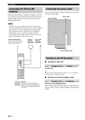
...window. In the standby mode, this unit. • A properly installed outdoor antenna provides clearer reception than an indoor one. Consult the nearest authorized Yamaha dealer or service center about outdoor antennas. • The AM loop antenna should be a 4 to 5-second delay before this unit can reproduce sound... a small amount of power in order to 32 ft) of vinyl-covered wire extended outdoors from the remote control. 18 En Connections Connecting the FM and AM antennas Both FM and AM indoor antennas are complete, plug the power cable into moist earth. model) Power...
...window. In the standby mode, this unit. • A properly installed outdoor antenna provides clearer reception than an indoor one. Consult the nearest authorized Yamaha dealer or service center about outdoor antennas. • The AM loop antenna should be a 4 to 5-second delay before this unit can reproduce sound... a small amount of power in order to 32 ft) of vinyl-covered wire extended outdoors from the remote control. 18 En Connections Connecting the FM and AM antennas Both FM and AM indoor antennas are complete, plug the power cable into moist earth. model) Power...
Owner's Manual
Page 23
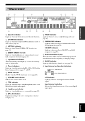
...Lights up while the sleep timer is reproducing PCM (Pulse Code Modulation) digital audio signals. 0 Headphones indicator Lights up when headphones are connected and a sound field program is selected (see page 33). 5 Input source indicators The corresponding cursor lights up to the set of ... speakers selected (see page 27). HiFi DSP indicator Lights up when you select a CINEMA DSP sound field program (see page 31). PREPARATION Front panel display Connections 1 2 3 4 5 67 8 t ENHANCER q DIGITAL q PL q PL PCM neural VIRTUAL DVR V-AUX DTV/CBL DVD SP SILENT CINEMA A B NIGHT...
...Lights up while the sleep timer is reproducing PCM (Pulse Code Modulation) digital audio signals. 0 Headphones indicator Lights up when headphones are connected and a sound field program is selected (see page 33). 5 Input source indicators The corresponding cursor lights up to the set of ... speakers selected (see page 27). HiFi DSP indicator Lights up when you select a CINEMA DSP sound field program (see page 31). PREPARATION Front panel display Connections 1 2 3 4 5 67 8 t ENHANCER q DIGITAL q PL q PL PCM neural VIRTUAL DVR V-AUX DTV/CBL DVD SP SILENT CINEMA A B NIGHT...

Owner's Manual
Page 24
... l PROGRAM h STRAIGHT NIGHT l INPUT h AUDIO SELECT EFFECT VIDEO VIDEO AUX L AUDIO R PORTABLE 30º 30º Approximately 6 m (20 ft) XInfrared window Outputs infrared control signals. Connections ■ Using the remote control The remote control transmits a directional infrared ray.
... l PROGRAM h STRAIGHT NIGHT l INPUT h AUDIO SELECT EFFECT VIDEO VIDEO AUX L AUDIO R PORTABLE 30º 30º Approximately 6 m (20 ft) XInfrared window Outputs infrared control signals. Connections ■ Using the remote control The remote control transmits a directional infrared ray.


