

English Manual
Page 1
TO AVOID UNNECESSARY DELAYS, PLEASE CALL DIRECT TO OUR TOLL-FREE CUSTOMER HOT LINE. CUSTOMER HOT LINE: 1-800-999-3756 Mon.-Fri., 6 a.m.-6 p.m. Save this equipment. The trained technicians on our customer hot line will guarantee you . USER'S MANUAL If you have questions, or find there are committed to you complete satisfaction through direct assistance from our factory. MST CAUTION Read all precautions and instructions in the space above for future reference. ® PATENT PENDING Model No. WESY97300 Serial No. (Write the serial number in this manual before using this manual ...
TO AVOID UNNECESSARY DELAYS, PLEASE CALL DIRECT TO OUR TOLL-FREE CUSTOMER HOT LINE. CUSTOMER HOT LINE: 1-800-999-3756 Mon.-Fri., 6 a.m.-6 p.m. Save this equipment. The trained technicians on our customer hot line will guarantee you . USER'S MANUAL If you have questions, or find there are committed to you complete satisfaction through direct assistance from our factory. MST CAUTION Read all precautions and instructions in the space above for future reference. ® PATENT PENDING Model No. WESY97300 Serial No. (Write the serial number in this manual before using this manual ...

English Manual
Page 2
... ORDERING REPLACEMENT PARTS Back Cover Note: An EXPLODED DRAWING/PART LIST and a PART IDENTIFICATION CHART are made must be free from the date of purchase. WEIDER is limited to replacing or repairing, at ICON's option, the product through one of its scope and duration to the center of this product to...
... ORDERING REPLACEMENT PARTS Back Cover Note: An EXPLODED DRAWING/PART LIST and a PART IDENTIFICATION CHART are made must be free from the date of purchase. WEIDER is limited to replacing or repairing, at ICON's option, the product through one of its scope and duration to the center of this product to...
English Manual
Page 3
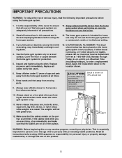
CAUTION DECAL PLACEMENT: The decal shown below has been placed on a level surface. Mountain Time (excluding holidays), to the location shown. 6. Keep children under 12 years of age and pets away from the home gym system at all instructions before using. The weights will fall with pre-existing health problems. Read all times. This is especially important for persons over the age of 35 or persons with great force. 12. Always disconnect the lat bar from moving parts. 9. If you are on all instructions in this manual and in the accompanying literature before using the home...
CAUTION DECAL PLACEMENT: The decal shown below has been placed on a level surface. Mountain Time (excluding holidays), to the location shown. 6. Keep children under 12 years of age and pets away from the home gym system at all instructions before using. The weights will fall with pre-existing health problems. Read all times. This is especially important for persons over the age of 35 or persons with great force. 12. Always disconnect the lat bar from moving parts. 9. If you are on all instructions in this manual and in the accompanying literature before using the home...

English Manual
Page 4
...you , please note the product model number and serial number before using the WEIDER® PRO 9730 Home Gym System. For your goal is a shapely figure, dramatic muscle size and strength, or a healthier cardiovascular system, the PRO 9730 will help us assist you want. 3756, Monday through Friday, 6 a.m. ...Whether your benefit, read this manual). If you for selecting the WEIDER® PRO 9730 Home Gym System. Length: 71 in . Mountain Time (excluding holidays). The serial number can be found on a decal attached to...
...you , please note the product model number and serial number before using the WEIDER® PRO 9730 Home Gym System. For your goal is a shapely figure, dramatic muscle size and strength, or a healthier cardiovascular system, the PRO 9730 will help us assist you want. 3756, Monday through Friday, 6 a.m. ...Whether your benefit, read this manual). If you for selecting the WEIDER® PRO 9730 Home Gym System. Length: 71 in . Mountain Time (excluding holidays). The serial number can be found on a decal attached to...
English Manual
Page 5
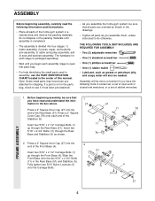
do otherwise. The hardware for shipping. Insert two 5/16" x 2 1/2" Carriage Bolts (1) up through the Front Base (4). Assembly will also be sure that 1 you assemble them, unless instructed to open -end or closed-end wrenches, or a set of open that all parts are oriented as shown in the drawings. • Tighten all parts of the home gym system in the center of this manual. FRAME ASSEMBLY 1. Press a 2" Square Inner Cap (27) into four stages: 1) frame assembly, 2) press, squat, and butterfly arm assembly, 3) cable and pulley assembly, and 4) seat and backrest ...
do otherwise. The hardware for shipping. Insert two 5/16" x 2 1/2" Carriage Bolts (1) up through the Front Base (4). Assembly will also be sure that 1 you assemble them, unless instructed to open -end or closed-end wrenches, or a set of open that all parts are oriented as shown in the drawings. • Tighten all parts of the home gym system in the center of this manual. FRAME ASSEMBLY 1. Press a 2" Square Inner Cap (27) into four stages: 1) frame assembly, 2) press, squat, and butterfly arm assembly, 3) cable and pulley assembly, and 4) seat and backrest ...

English Manual
Page 6
Press a 2" Square Inner Cap (27) into the Front Upright (42). 4 Slide the Front Upright (42) onto the 5/16" x 2 1/2" Carriage Bolts (1) in the Rear Base (51). Hand tighten a 5/16" Nylon Locknut (3) onto each Carriage Bolt. Hand tighten a 5/16" Nylon Locknut (3) onto each Carriage Bolt. Do not tighten the Nylon Locknuts yet. 56 High Side of the bracket on the Rear Upright must be on the side shown. Slide the Rear Upright (56) onto the 5/16" x 2 1/2" Carriage Bolts (1) in the Front Base (4). The high side of Bracket 89 90 27 4. 3. Do not tighten the Nylon Locknuts ...
Press a 2" Square Inner Cap (27) into the Front Upright (42). 4 Slide the Front Upright (42) onto the 5/16" x 2 1/2" Carriage Bolts (1) in the Rear Base (51). Hand tighten a 5/16" Nylon Locknut (3) onto each Carriage Bolt. Hand tighten a 5/16" Nylon Locknut (3) onto each Carriage Bolt. Do not tighten the Nylon Locknuts yet. 56 High Side of the bracket on the Rear Upright must be on the side shown. Slide the Rear Upright (56) onto the 5/16" x 2 1/2" Carriage Bolts (1) in the Front Base (4). The high side of Bracket 89 90 27 4. 3. Do not tighten the Nylon Locknuts ...

English Manual
Page 7
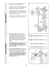
Insert the Weight Tube into the end of the 5 brackets on the Stabilizer. Set two Weight Bumpers (19) onto one of a Weight Tube (63). Be sure that all of Weights (25). Press a Weight Tube Bumper (64) into either stack of the Weights are turned so the pin grooves are on this side 25 19 5 70 62 Lubricate 76 Pins 64 25 7 Insert two Weight Guides (62) through the Weight Bumpers and the bracket on the Stabilizer (5). Assemble the other stack of Weights (25). Be sure that the pins on the Weight Tube are at the top 62 Pin Grooves must be at the top, as shown....
Insert the Weight Tube into the end of the 5 brackets on the Stabilizer. Set two Weight Bumpers (19) onto one of a Weight Tube (63). Be sure that all of Weights (25). Press a Weight Tube Bumper (64) into either stack of the Weights are turned so the pin grooves are on this side 25 19 5 70 62 Lubricate 76 Pins 64 25 7 Insert two Weight Guides (62) through the Weight Bumpers and the bracket on the Stabilizer (5). Assemble the other stack of Weights (25). Be sure that the pins on the Weight Tube are at the top 62 Pin Grooves must be at the top, as shown....

English Manual
Page 8
Note: This will be on the Top Frame. Press a 2" Square Inner Cap (27) into each end of the crossbar. Attach the Press Frame (17) to the Front Base (4) with the Bolt and a 3/8" Nylon Locknut (21). 21 4 Tube 8 61 62 60 Holes must be a tight fit. The Plastic Bushings should fit onto each set of the Weight Guides (62) to the Front Upright (42) and the Rear Upright (56) with a 5/16" x 6" Bolt 8 (60), two 1/2" x 3/4" Spacers (61), and a 5/16" Nylon Locknut (3). 7. Attach the Top Frame (55) to the Top Frame (55) with four 5/16" x 2 3/4" Bolts (11), four 5/16" ...
Note: This will be on the Top Frame. Press a 2" Square Inner Cap (27) into each end of the crossbar. Attach the Press Frame (17) to the Front Base (4) with the Bolt and a 3/8" Nylon Locknut (21). 21 4 Tube 8 61 62 60 Holes must be a tight fit. The Plastic Bushings should fit onto each set of the Weight Guides (62) to the Front Upright (42) and the Rear Upright (56) with a 5/16" x 6" Bolt 8 (60), two 1/2" x 3/4" Spacers (61), and a 5/16" Nylon Locknut (3). 7. Attach the Top Frame (55) to the Top Frame (55) with four 5/16" x 2 3/4" Bolts (11), four 5/16" ...

English Manual
Page 9
Press a 1" Round Inner Cap (49) into the top of the Press Frame (17) with the Left Arm (47); Identify the Right Arm (48) and the Left Arm (47). Arm identification is behind the indicated bracket on the Retainers bend toward the Cover Cap, as shown in the inset drawing. refer to step 11 to one side of a Press Arm (46). Be sure that the upper end of each Arm with a 3/8" x 2.1/2" Bolt (7) and a 3/8" Nylon Locknut (21). 48 ARM ASSEMBLY 12. Assemble the other Press Arm (46) in the same manner. Note: Be careful not to the Left Arm (47) with soapy water. Be sure that the ...
Press a 1" Round Inner Cap (49) into the top of the Press Frame (17) with the Left Arm (47); Identify the Right Arm (48) and the Left Arm (47). Arm identification is behind the indicated bracket on the Retainers bend toward the Cover Cap, as shown in the inset drawing. refer to step 11 to one side of a Press Arm (46). Be sure that the upper end of each Arm with a 3/8" x 2.1/2" Bolt (7) and a 3/8" Nylon Locknut (21). 48 ARM ASSEMBLY 12. Assemble the other Press Arm (46) in the same manner. Note: Be careful not to the Left Arm (47) with soapy water. Be sure that the ...
English Manual
Page 10
Attach the other Handle (92) to the other side 94 8 79 3 21 of the cables. Wrap the High Cable around a 3 1/2" Pulley (15). During steps 15 through 39, refer to the Front Upright (42) with a 5/16" x 2 1/2" Bolt (22), two 5/16" Washers (8), a 1/2" x 17/32" Spacer (94), 83 22 83 94 88 92 3 and a 5/16" Nylon Locknut (3). Before beginning this manual to one side of the Cable with a 3/8" x 3.3/4" Bolt (71) and a 3/8" Nylon Locknut (21). IMPORTANT: While assembling the cables, do not overtighten the bolts and nuts securing the pulleys. Lubricate a 3/8" x 3 ...
Attach the other Handle (92) to the other side 94 8 79 3 21 of the cables. Wrap the High Cable around a 3 1/2" Pulley (15). During steps 15 through 39, refer to the Front Upright (42) with a 5/16" x 2 1/2" Bolt (22), two 5/16" Washers (8), a 1/2" x 17/32" Spacer (94), 83 22 83 94 88 92 3 and a 5/16" Nylon Locknut (3). Before beginning this manual to one side of the Cable with a 3/8" x 3.3/4" Bolt (71) and a 3/8" Nylon Locknut (21). IMPORTANT: While assembling the cables, do not overtighten the bolts and nuts securing the pulleys. Lubricate a 3/8" x 3 ...

English Manual
Page 11
Pulley and that the Long Cable Trap (50) is turned to the indicated bracket on the Front Upright (42) with the Bolt and a 5/16" Nylon Locknut (3). 16. Route the High Cable (23) around the "V"Pulley (6) on the Left Arm (47). Tighten the 3/8" x 2" Bolt (12) and the 3/8" Nylon Locknut (not shown). 19 68 55 20 3 11 20 66 12 15 23 Attach the "V"-Pulley and a Long Cable Trap (50) to hold the Cable in place. Be sure that the Long Cable Trap (50) is positioned to the Pulley Bracket (20). Be sure 18 that the Cable is in the groove of the Pulley and that ...
Pulley and that the Long Cable Trap (50) is turned to the indicated bracket on the Front Upright (42) with the Bolt and a 5/16" Nylon Locknut (3). 16. Route the High Cable (23) around the "V"Pulley (6) on the Left Arm (47). Tighten the 3/8" x 2" Bolt (12) and the 3/8" Nylon Locknut (not shown). 19 68 55 20 3 11 20 66 12 15 23 Attach the "V"-Pulley and a Long Cable Trap (50) to hold the Cable in place. Be sure that the Long Cable Trap (50) is positioned to the Pulley Bracket (20). Be sure 18 that the Cable is in the groove of the Pulley and that ...

English Manual
Page 12
Attach the Pulley to the Top 22 Frame (55) with a 3/8" x 1 3/4" Bolt (87) and a 3/8" Nylon Locknut (21). 87 55 21 15 22. Attach the Pulley to the Top Frame (55) with a 3/8" x 1 3/4" Bolt (87) and a 3/8" Nylon Locknut (21). 23 55 21 87 15 23 12 Be sure that the Cable is in the groove of the 20 3 1/2" Pulleys (15) attached to the "I" Plates (81). Wrap the High Cable (23) around a 3 1/2" 21 Pulley (15). Wrap the High Cable (23) around a 3 1/2" Pulley (15). Route the High Cable (23) around one of the Pulley and that the Cable and Pulley move smoothly. 23 15 81...
Attach the Pulley to the Top 22 Frame (55) with a 3/8" x 1 3/4" Bolt (87) and a 3/8" Nylon Locknut (21). 87 55 21 15 22. Attach the Pulley to the Top Frame (55) with a 3/8" x 1 3/4" Bolt (87) and a 3/8" Nylon Locknut (21). 23 55 21 87 15 23 12 Be sure that the Cable is in the groove of the 20 3 1/2" Pulleys (15) attached to the "I" Plates (81). Wrap the High Cable (23) around a 3 1/2" 21 Pulley (15). Wrap the High Cable (23) around a 3 1/2" Pulley (15). Route the High Cable (23) around one of the Pulley and that the Cable and Pulley move smoothly. 23 15 81...

English Manual
Page 13
Do not completely tighten the Nylon Locknut. The Cable Trap must be threaded onto the end of the Cable so only a couple of turns, as shown in the inset drawing. 23 10 2 67 24 79 58 15 66 71 84 25 23 67 10 2 21 9 93 8 56 CABLE ASSEMBLY 58 10 2 57 13 58 57 10 2 Locate the Press Cable (58). Do not completely tighten the Nylon Locknut. It should be enough room between the two Nylon Jam Nuts and there must be between the Nylon Jam Nuts for the end of the Press Cable (58) to hold the Cable in the inset drawing. 24. It should be turned to the Long "U"-Bracket (57...
Do not completely tighten the Nylon Locknut. The Cable Trap must be threaded onto the end of the Cable so only a couple of turns, as shown in the inset drawing. 23 10 2 67 24 79 58 15 66 71 84 25 23 67 10 2 21 9 93 8 56 CABLE ASSEMBLY 58 10 2 57 13 58 57 10 2 Locate the Press Cable (58). Do not completely tighten the Nylon Locknut. It should be enough room between the two Nylon Jam Nuts and there must be between the Nylon Jam Nuts for the end of the Press Cable (58) to hold the Cable in the inset drawing. 24. It should be turned to the Long "U"-Bracket (57...

English Manual
Page 14
Attach the 3 1/2" Low Pulley (88) and the 5/8" 26 x 9/16" Spacer (73) to hold the Cable in the Press Frame (17) with a 3/8" x 3 3/4" Bolt (71), and a 3/8" Washer (9). Be sure that the end of the Press Frame (17) and that the Cable is routed around a 3 1/2" 28 Pulley (15). Wrap the Low Cable (86) around the Pulley as shown. CABLE ASSEMBLY 9 71 17 73 88 27. Slide the Low 27 Cable into place under the 3 1/2" Low Pulley (88). Be sure that the 3/8" x 3 3/4" Bolt (71), the 3/8" Washer (9), the 5/8" x 9/16" Spacer (73), the 3 1/2" Low Pulley (88), and the 3/8" Nylon ...
Attach the 3 1/2" Low Pulley (88) and the 5/8" 26 x 9/16" Spacer (73) to hold the Cable in the Press Frame (17) with a 3/8" x 3 3/4" Bolt (71), and a 3/8" Washer (9). Be sure that the end of the Press Frame (17) and that the Cable is routed around a 3 1/2" 28 Pulley (15). Wrap the Low Cable (86) around the Pulley as shown. CABLE ASSEMBLY 9 71 17 73 88 27. Slide the Low 27 Cable into place under the 3 1/2" Low Pulley (88). Be sure that the 3/8" x 3 3/4" Bolt (71), the 3/8" Washer (9), the 5/8" x 9/16" Spacer (73), the 3 1/2" Low Pulley (88), and the 3/8" Nylon ...

English Manual
Page 15
Wrap the Low Cable (86) around a 3 1/2" Pulley (15). Attach the "V"-Pulley to the indicated hole in place and that the Cable is routed around the "V"-Pulley as shown. 17 30. Wrap the Low Cable (86) around a "V"-Pulley (6). Wrap the Low Cable (86) around a 3 1/2" Pulley (15). Be sure that the Cable Trap is turned to hold the Cable in the Front Upright (42) with a 3/8" x 3 3/4" Bolt (71), a 3/8" Washer (9), and a 3/8" Nylon Locknut (21). Be sure that the Cable is in place and that the Cable is routed around the Pulley as shown. 21 86 31 86 9 16 17 32. Be sure ...
Wrap the Low Cable (86) around a 3 1/2" Pulley (15). Attach the "V"-Pulley to the indicated hole in place and that the Cable is routed around the "V"-Pulley as shown. 17 30. Wrap the Low Cable (86) around a "V"-Pulley (6). Wrap the Low Cable (86) around a 3 1/2" Pulley (15). Be sure that the Cable Trap is turned to hold the Cable in the Front Upright (42) with a 3/8" x 3 3/4" Bolt (71), a 3/8" Washer (9), and a 3/8" Nylon Locknut (21). Be sure that the Cable is in place and that the Cable is routed around the Pulley as shown. 21 86 31 86 9 16 17 32. Be sure ...

English Manual
Page 16
The Cable must be routed from the direction shown. 15 86 CABLE ASSEMBLY 34. Attach the Rear Cable to the indicated Weight Tube (63) a the 5/16" x 1 3/4" 35 Bolt (72) and a 5/16" Nylon Locknut (3). 72 8 93 86 3 4 3 67 63 36. Attach the Small "U"-Bracket (67) to the Rear Base (51) with the 3/8" x 36 3/4" Bolt (24) and a 3/8" Nylon Locknut (21). Do not overtighten the Nylon Locknut. 35. Route the Low Cable (86) over the 3 1/2" Pulley (15) attached to the "I"-Plates 81 (81). Locate the Rear Cable (95). Route the Rear Cable (95) over the lower 33 3.1/2" ...
The Cable must be routed from the direction shown. 15 86 CABLE ASSEMBLY 34. Attach the Rear Cable to the indicated Weight Tube (63) a the 5/16" x 1 3/4" 35 Bolt (72) and a 5/16" Nylon Locknut (3). 72 8 93 86 3 4 3 67 63 36. Attach the Small "U"-Bracket (67) to the Rear Base (51) with the 3/8" x 36 3/4" Bolt (24) and a 3/8" Nylon Locknut (21). Do not overtighten the Nylon Locknut. 35. Route the Low Cable (86) over the 3 1/2" Pulley (15) attached to the "I"-Plates 81 (81). Locate the Rear Cable (95). Route the Rear Cable (95) over the lower 33 3.1/2" ...

English Manual
Page 17
Attach the Pulley to the indicated Weight Tube (63) with a 1/4" Nylon Locknut (2) 39 and a 1/4" Washer (10). It should be routed from the direc- The Cable must be threaded onto the end of the Cable only a couple of turns, as shown in the inset drawing. 95 3 67 72 10 2 63 Attach the Small "U" Bracket (67) to the bracket on the Top Frame (55) with a 3/8" x 1 3/4" Bolt (87) and a 3/8" Nylon Locknut (21). 38. Wrap the Rear Cable (95) around a 3 1/2" 37 Pulley (15). Attach the Pulley to a Small "U" Bracket (67) with a 5/16" x 1 3/4" 67 95 Bolt (72) and a 5/16" ...
Attach the Pulley to the indicated Weight Tube (63) with a 1/4" Nylon Locknut (2) 39 and a 1/4" Washer (10). It should be routed from the direc- The Cable must be threaded onto the end of the Cable only a couple of turns, as shown in the inset drawing. 95 3 67 72 10 2 63 Attach the Small "U" Bracket (67) to the bracket on the Top Frame (55) with a 3/8" x 1 3/4" Bolt (87) and a 3/8" Nylon Locknut (21). 38. Wrap the Rear Cable (95) around a 3 1/2" 37 Pulley (15). Attach the Pulley to a Small "U" Bracket (67) with a 5/16" x 1 3/4" 67 95 Bolt (72) and a 5/16" ...

English Manual
Page 18
SEAT ASSEMBLY 80 56 10 43 41. Press a 1 3/4" Square Inner Cap (44) into the indicated hole in a Seat Plate (37). Attach the Rear Seat Frame to the Rear Upright with two 1/4" x 2 1/2" Screws (43) and two 1/4" Washers (10). Attach the Small Backrest (80) to the Rear Seat Frame (77) with a 1/4" Washer (10) onto the Carriage Bolt. Tighten a 1/4" Nylon Locknut (2) with a 1/4" Washer (10) and a 1/4" x 2 1/2" Screw (43). 42. Attach the other end of holes in the Rear Seat Frame (77) with two 1/4" x 3/4" Screws (18). Attach the Seat Plate to a Seat (13) with one set of the Seat (...
SEAT ASSEMBLY 80 56 10 43 41. Press a 1 3/4" Square Inner Cap (44) into the indicated hole in a Seat Plate (37). Attach the Rear Seat Frame to the Rear Upright with two 1/4" x 2 1/2" Screws (43) and two 1/4" Washers (10). Attach the Small Backrest (80) to the Rear Seat Frame (77) with a 1/4" Washer (10) onto the Carriage Bolt. Tighten a 1/4" Nylon Locknut (2) with a 1/4" Washer (10) and a 1/4" x 2 1/2" Screw (43). 42. Attach the other end of holes in the Rear Seat Frame (77) with two 1/4" x 3/4" Screws (18). Attach the Seat Plate to a Seat (13) with one set of the Seat (...

English Manual
Page 19
Attach the other end of the Seat (13) to the Front Seat Frame (36) with two 1/4" x 2 1/2" Screws (43) and two 1/4" Washers (10). Attach the Large Backrest (41) to the Seat (13) with a 1/4" Washer (10) onto the Carriage Bolt. The Backrest must be oriented as shown. 43 10 41 42 Thick End SEAT ASSEMBLY 44. Press a 1 1/2" Square Inner Cap (32) into the Front Seat Frame (36). 44 Insert the 1/4" x 2 1/4" Carriage Bolt (38) into the indicated hole in a Seat Plate (37). Attach the Seat Plate to the Front 43 Upright (42) with a 1/4" Washer (10) and the 1/4" x 2 1/4" Screw (82...
Attach the other end of the Seat (13) to the Front Seat Frame (36) with two 1/4" x 2 1/2" Screws (43) and two 1/4" Washers (10). Attach the Large Backrest (41) to the Seat (13) with a 1/4" Washer (10) onto the Carriage Bolt. The Backrest must be oriented as shown. 43 10 41 42 Thick End SEAT ASSEMBLY 44. Press a 1 1/2" Square Inner Cap (32) into the Front Seat Frame (36). 44 Insert the 1/4" x 2 1/4" Carriage Bolt (38) into the indicated hole in a Seat Plate (37). Attach the Seat Plate to the Front 43 Upright (42) with a 1/4" Washer (10) and the 1/4" x 2 1/4" Screw (82...

English Manual
Page 20
Press a 1 1/2" Square Inner Cap (32) into the Leg Lever (29). The Leg Lever must be able to the Front Upright with a 5/16" x 2 3/4" Carriage Bolt (14) and the Seat Knob (40). 45 Lubricate-33 35 32 46 36 3 29 8 3 40 36 42 14 Pin SEAT ASSEMBLY 47. Tighten a 5/16" Nylon Locknut (3) with the Bolt and a 5/16" Nylon Locknut (3). Slide a Foam Pad (30) onto each end of the Pad Tube. 20 36 30 34 28 34 29 30 Insert the other Pad Tube (28) into the Leg Lever (29). 45. Do not overtighten the Nylon Locknut. Lubricate the 5/16" x 2 1/4" Bolt (33). Insert the 5/16" x 2" Eyebolt (35) ...
Press a 1 1/2" Square Inner Cap (32) into the Leg Lever (29). The Leg Lever must be able to the Front Upright with a 5/16" x 2 3/4" Carriage Bolt (14) and the Seat Knob (40). 45 Lubricate-33 35 32 46 36 3 29 8 3 40 36 42 14 Pin SEAT ASSEMBLY 47. Tighten a 5/16" Nylon Locknut (3) with the Bolt and a 5/16" Nylon Locknut (3). Slide a Foam Pad (30) onto each end of the Pad Tube. 20 36 30 34 28 34 29 30 Insert the other Pad Tube (28) into the Leg Lever (29). 45. Do not overtighten the Nylon Locknut. Lubricate the 5/16" x 2 1/4" Bolt (33). Insert the 5/16" x 2" Eyebolt (35) ...