

English Manual
Page 1
... missing or damaged parts, we are committed to you complete satisfaction through direct assistance from our factory. MST CAUTION Read all precautions and instructions in the space above for future reference. USER'S MANUAL WESY97300 Serial No. (Write the serial number in this manual before using this manual for reference.) Serial Number Decal QUESTIONS? TO AVOID UNNECESSARY DELAYS, PLEASE CALL DIRECT TO OUR TOLL-FREE CUSTOMER HOT...
... missing or damaged parts, we are committed to you complete satisfaction through direct assistance from our factory. MST CAUTION Read all precautions and instructions in the space above for future reference. USER'S MANUAL WESY97300 Serial No. (Write the serial number in this manual before using this manual for reference.) Serial Number Decal QUESTIONS? TO AVOID UNNECESSARY DELAYS, PLEASE CALL DIRECT TO OUR TOLL-FREE CUSTOMER HOT...

English Manual
Page 2
... normal use , costs of removal, installation or other warranty beyond that specifically set forth herein. All repairs for a period of ninety (90) days from state to you specific legal rights. This warranty does not extend to any implied warranties of ICON Health & Fitness, Inc. Some states do not allow limitations on how long an implied warranty lasts. Remove the EXPLODED DRAWING/PART LIST and the PART IDENTIFICATION CHART before beginning assembly...
... normal use , costs of removal, installation or other warranty beyond that specifically set forth herein. All repairs for a period of ninety (90) days from state to you specific legal rights. This warranty does not extend to any implied warranties of ICON Health & Fitness, Inc. Some states do not allow limitations on how long an implied warranty lasts. Remove the EXPLODED DRAWING/PART LIST and the PART IDENTIFICATION CHART before beginning assembly...
English Manual
Page 3
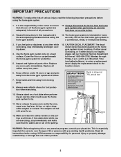
... the press arm, butterfly arms, squat arm, leg lever, lat bar, or nylon strap while weights are on a level surface. Make sure that does not use the home gym system in two locations. WARNING: Before beginning this product. 3 ICON assumes no responsibility for home use of this or any worn parts immediately. Always disconnect the lat bar from the home gym system when performing an exercise that the cables remain on the home gym system...
... the press arm, butterfly arms, squat arm, leg lever, lat bar, or nylon strap while weights are on a level surface. Make sure that does not use the home gym system in two locations. WARNING: Before beginning this product. 3 ICON assumes no responsibility for home use of this or any worn parts immediately. Always disconnect the lat bar from the home gym system when performing an exercise that the cables remain on the home gym system...

English Manual
Page 4
... a healthier cardiovascular system, the PRO 9730 will help us assist you, please note the product model number and serial number before using the WEIDER® PRO 9730 Home Gym System. Width: 34 in . Length: 71 in . The serial number can be found on a decal attached to achieve the specific results you to the WEIDER® PRO 9730 (see the front cover of the body. High Pulley Station Lat Bar ASSEMBLED DIMENSIONS: Height: 78 in. Mountain Time...
... a healthier cardiovascular system, the PRO 9730 will help us assist you, please note the product model number and serial number before using the WEIDER® PRO 9730 Home Gym System. Width: 34 in . Length: 71 in . The serial number can be found on a decal attached to achieve the specific results you to the WEIDER® PRO 9730 (see the front cover of the body. High Pulley Station Lat Bar ASSEMBLED DIMENSIONS: Height: 78 in. Mountain Time...
English Manual
Page 5
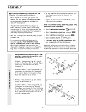
... set, a set of open that all parts are oriented as shown in the drawings. • Tighten all parts of the home gym system in the center of this manual. Insert two 5/16" x 2 3/4" Bolts (11) through the Rear Base and Stabilizer (5) as grease or petroleum jelly, and soapy water will be sure that parts bag. • For help identifying the small parts used in assembly, use the PART IDENTIFICATION CHART located...
... set, a set of open that all parts are oriented as shown in the drawings. • Tighten all parts of the home gym system in the center of this manual. Insert two 5/16" x 2 3/4" Bolts (11) through the Rear Base and Stabilizer (5) as grease or petroleum jelly, and soapy water will be sure that parts bag. • For help identifying the small parts used in assembly, use the PART IDENTIFICATION CHART located...

English Manual
Page 8
... Rear Upright (56) with the Bolt and a 3/8" Nylon Locknut (21). 21 4 Tube 8 61 62 60 Holes must be a tight fit. Attach the each end of the crossbar. Lubricate the 3/8" x 8" Bolt (59). Press a 1 3/4" Square Inner Cap (44) into the top of the Top Frame (55). Press a 1" x 7/8" Plastic Bushing (75) onto each welded spacer on this side Lubricate 59 Welded Spacers 75 ARM ASSEMBLY 7. Press...
... Rear Upright (56) with the Bolt and a 3/8" Nylon Locknut (21). 21 4 Tube 8 61 62 60 Holes must be a tight fit. Attach the each end of the crossbar. Lubricate the 3/8" x 8" Bolt (59). Press a 1 3/4" Square Inner Cap (44) into the top of the Top Frame (55). Press a 1" x 7/8" Plastic Bushing (75) onto each welded spacer on this side Lubricate 59 Welded Spacers 75 ARM ASSEMBLY 7. Press...
English Manual
Page 10
Attach the Squat Arm (79) to verify proper cable routing. Lubricate a 3/8" x 3 1/4" Bolt (85). Attach the other Handle (92) to the other side 94 8 79 3 21 of 14 this section, identify the High Cable (23), the Low Cable (86), the Rear Cable (95), and the Press Cable (58) by comparing the lengths and ends of the Pulley and that the Cable is between the Pulley and the hook...
Attach the Squat Arm (79) to verify proper cable routing. Lubricate a 3/8" x 3 1/4" Bolt (85). Attach the other Handle (92) to the other side 94 8 79 3 21 of 14 this section, identify the High Cable (23), the Low Cable (86), the Rear Cable (95), and the Press Cable (58) by comparing the lengths and ends of the Pulley and that the Cable is between the Pulley and the hook...

English Manual
Page 14
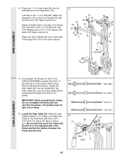
... Note: You may need to remove the 3 1/2" Low Pulley (88) from the 3/8" x 3 3/4" Bolt (71) to hold the Cable in place and that the Cable is routed around a 3 1/2" 28 Pulley (15). 26. Fully tighten a 3/8" Nylon Locknut (21) onto the 3/8" x 3 3/4" Bolt (71). Slide the Low 27 Cable into place under the 3 1/2" Low Pulley (88). Be sure that the end of the Press Frame (17) and...
... Note: You may need to remove the 3 1/2" Low Pulley (88) from the 3/8" x 3 3/4" Bolt (71) to hold the Cable in place and that the Cable is routed around a 3 1/2" 28 Pulley (15). 26. Fully tighten a 3/8" Nylon Locknut (21) onto the 3/8" x 3 3/4" Bolt (71). Slide the Low 27 Cable into place under the 3 1/2" Low Pulley (88). Be sure that the end of the Press Frame (17) and...

English Manual
Page 16
... 63 36. 33. Route the Low Cable (86) over the 3 1/2" Pulley (15) attached to the "I"-Plates 81 (81). Route the Rear Cable (95) over the lower 33 3.1/2" Pulley (15) attached to the Long "U"-Bracket (57). 16 57 15 24 51 95 21 The Cable must be routed from the direction shown. 15 86 CABLE ASSEMBLY 34. Slide theend of the Press Cable (88) onto the Bolt. Locate the Rear Cable (95).
... 63 36. 33. Route the Low Cable (86) over the 3 1/2" Pulley (15) attached to the "I"-Plates 81 (81). Route the Rear Cable (95) over the lower 33 3.1/2" Pulley (15) attached to the Long "U"-Bracket (57). 16 57 15 24 51 95 21 The Cable must be routed from the direction shown. 15 86 CABLE ASSEMBLY 34. Slide theend of the Press Cable (88) onto the Bolt. Locate the Rear Cable (95).

English Manual
Page 17
It should be routed from the direc- Attach the Pulley to the bracket on the Top Frame (55) with a 3/8" x 1 3/4" Bolt (87) and a 3/8" Nylon Locknut (21). 38. Do not completely tighten the Nylon Locknut. Attach the Pulley to the indicated bracket on the Stabilizer (5) with a 3/8" x 1.3/4" Bolt (87) and a 3/8" Nylon Locknut (21). Wrap the Rear Cable (95) around a 3 1/2" 37 Pulley (15). The Cable must be...
It should be routed from the direc- Attach the Pulley to the bracket on the Top Frame (55) with a 3/8" x 1 3/4" Bolt (87) and a 3/8" Nylon Locknut (21). 38. Do not completely tighten the Nylon Locknut. Attach the Pulley to the indicated bracket on the Stabilizer (5) with a 3/8" x 1.3/4" Bolt (87) and a 3/8" Nylon Locknut (21). Wrap the Rear Cable (95) around a 3 1/2" 37 Pulley (15). The Cable must be...

English Manual
Page 21
... properly installed, they may be sure that all parts have been properly tightened. Remove the backing from the PRO 9730 48 decal and apply it by tightening the cables. Before using the home gym system, pull each cable a few times to the home gym system as shown. Make sure that the cables move smoothly, find and correct the problem. The use of this manual for proper cable routing. See TROUBLE-SHOOTING AND MAINTENANCE...
... properly installed, they may be sure that all parts have been properly tightened. Remove the backing from the PRO 9730 48 decal and apply it by tightening the cables. Before using the home gym system, pull each cable a few times to the home gym system as shown. Make sure that the cables move smoothly, find and correct the problem. The use of this manual for proper cable routing. See TROUBLE-SHOOTING AND MAINTENANCE...
English Manual
Page 22
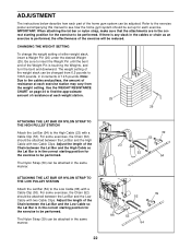
... the home gym system can be changed from the weight setting. Be sure to be adjusted. For some exercises, the Chain (52) should be set up for each part of the Weight Pin is in the correct starting position for the exercise to the Low Cable (86) with two Cable Clips. ATTACHING THE LAT BAR OR NYLON STRAP TO THE LOW PULLEY STATION Attach the Lat Bar (54) to be attached between the Lat Bar and...
... the home gym system can be changed from the weight setting. Be sure to be adjusted. For some exercises, the Chain (52) should be set up for each part of the Weight Pin is in the correct starting position for the exercise to the Low Cable (86) with two Cable Clips. ATTACHING THE LAT BAR OR NYLON STRAP TO THE LOW PULLEY STATION Attach the Lat Bar (54) to be attached between the Lat Bar and...

English Manual
Page 23
... holes in the Rear Upright (56). ATTACHING THE LEG LEVER TO THE LOW PULLEY STATION To use the Leg Lever (29), the seat must be sure that the chain is not attached to the leg lever. Set the bracket on the Front Seat Frame (36) onto the indicated pins on the Front Upright (42). Next, remove the Seat Knob (40) and the 5/16" x 2 3/4" Carriage Bolt (14) from the...
... holes in the Rear Upright (56). ATTACHING THE LEG LEVER TO THE LOW PULLEY STATION To use the Leg Lever (29), the seat must be sure that the chain is not attached to the leg lever. Set the bracket on the Front Seat Frame (36) onto the indicated pins on the Front Upright (42). Next, remove the Seat Knob (40) and the 5/16" x 2 3/4" Carriage Bolt (14) from the...

English Manual
Page 24
The other numbers refer to the 6.5 lb. "Top" refers to the 12.5 lb. WEIGHT PLATES PRESS ARM (lbs.) BUTTERFLY ARM (lbs.) LEG LEVER (lbs.) HIGH PULLEY (lbs.) LOW PULLEY (lbs.) SQUAT ARM (lbs.) Top 24 14 21 15 19 31 1 45 21 ... actual resistance at each station. top weight. weight plates. WEIGHT RESISTANCE CHART This chart shows the approximate weight resistance at each weight station may vary due to differences in individual weight plates, as well as friction between the cables, pulleys, and weight guides. 24 Weight resistance shown for the butterfly arm station ...
The other numbers refer to the 6.5 lb. "Top" refers to the 12.5 lb. WEIGHT PLATES PRESS ARM (lbs.) BUTTERFLY ARM (lbs.) LEG LEVER (lbs.) HIGH PULLEY (lbs.) LOW PULLEY (lbs.) SQUAT ARM (lbs.) Top 24 14 21 15 19 31 1 45 21 ... actual resistance at each station. top weight. weight plates. WEIGHT RESISTANCE CHART This chart shows the approximate weight resistance at each weight station may vary due to differences in individual weight plates, as well as friction between the cables, pulleys, and weight guides. 24 Weight resistance shown for the butterfly arm station ...

English Manual
Page 25
... Rear Cable (95) (see ORDERING REPLACEMENT PARTS on the home gym system, can be lifted off the pulleys often, the cable may need to be removed from the cables by moving the 3 1/2" Pulley (15) to remove the Small "U"-Bracket (67) from the Weight Tube (not shown) or remove the 3 1/2" Pulley (15) from the Cable Trap (66), Pulley, and "U"-Bracket. Re-attach the Pulley and Cable Trap. Be sure that the Cable and Pulley move smoothly. TIGHTENING...
... Rear Cable (95) (see ORDERING REPLACEMENT PARTS on the home gym system, can be lifted off the pulleys often, the cable may need to be removed from the cables by moving the 3 1/2" Pulley (15) to remove the Small "U"-Bracket (67) from the Weight Tube (not shown) or remove the 3 1/2" Pulley (15) from the Cable Trap (66), Pulley, and "U"-Bracket. Re-attach the Pulley and Cable Trap. Be sure that the Cable and Pulley move smoothly. TIGHTENING...
English Manual
Page 26
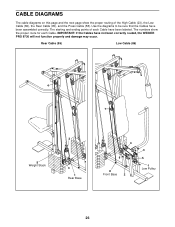
IMPORTANT: If the Cables have been assembled correctly. The numbers show the proper routing of each Cable. The starting and ending points of the High Cable (23), the Low Cable (86), the Rear Cable (95), and the Press Cable (58). Rear Cable (95) Low Cable (86) 4 7 5 Weight Stack 2 3 1 Rear Base 4 6 8 Front Base 2 3 5 1 Low Pulley 26 Use the diagrams to be sure that the Cables have not been correctly routed, the WEIDER PRO 9730 will not function...
IMPORTANT: If the Cables have been assembled correctly. The numbers show the proper routing of each Cable. The starting and ending points of the High Cable (23), the Low Cable (86), the Rear Cable (95), and the Press Cable (58). Rear Cable (95) Low Cable (86) 4 7 5 Weight Stack 2 3 1 Rear Base 4 6 8 Front Base 2 3 5 1 Low Pulley 26 Use the diagrams to be sure that the Cables have not been correctly routed, the WEIDER PRO 9730 will not function...

English Manual
Page 27
High Cable (23) 5 7 8 2 High Pulley 1 43 Press Cable (58) 2 1 Rear Upright 6 Weight Stack 9 3 Long "U" Bracket 27
High Cable (23) 5 7 8 2 High Pulley 1 43 Press Cable (58) 2 1 Rear Upright 6 Weight Stack 9 3 Long "U" Bracket 27
English Manual
Page 28
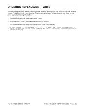
... through Friday, 6 a.m. The KEY NUMBER and DESCRIPTION of the part(s) (see the front cover of this manual). The MODEL NUMBER of the product (WEIDER® 9730 Home Gym System). 3. Mountain Time (excluding holidays). The NAME of the product (WESY97300). 2. Part No. 142239 G03529-C R1097A Printed in Canada © 1997 ICON Health & Fitness, Inc. ORDERING REPLACEMENT PARTS To order replacement parts, simply call our Customer Service Department toll-free at the center...
... through Friday, 6 a.m. The KEY NUMBER and DESCRIPTION of the part(s) (see the front cover of this manual). The MODEL NUMBER of the product (WEIDER® 9730 Home Gym System). 3. Mountain Time (excluding holidays). The NAME of the product (WESY97300). 2. Part No. 142239 G03529-C R1097A Printed in Canada © 1997 ICON Health & Fitness, Inc. ORDERING REPLACEMENT PARTS To order replacement parts, simply call our Customer Service Department toll-free at the center...
English Manual
Page 29
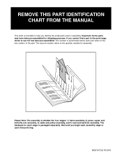
... Note: The assembly is packaged separately. WESY97300 R1097A REMOVE THIS PART IDENTIFICATION CHART FROM THE MANUAL This chart is provided to help you begin each assembly stage to open that parts bag. If you cannot find a part in assembly. Important: Some parts may have been pre-assembled for each stage is divided into four stages: 1) frame assembly, 2) press, squat, and butterfly arm assembly, 3) cable and pulley assembly, and 4) seat and backrest...
... Note: The assembly is packaged separately. WESY97300 R1097A REMOVE THIS PART IDENTIFICATION CHART FROM THE MANUAL This chart is provided to help you begin each assembly stage to open that parts bag. If you cannot find a part in assembly. Important: Some parts may have been pre-assembled for each stage is divided into four stages: 1) frame assembly, 2) press, squat, and butterfly arm assembly, 3) cable and pulley assembly, and 4) seat and backrest...

English Manual
Page 34
...2 3/4" Carriage Bolt 3 1/2" Pulley 3/8" x 3 1/2" Bolt Press Frame 1/4" x 3/4" Screw Weight Bumper Pulley Bracket 3/8" Nylon Locknut 5/16" x 2 1/2" Bolt High Cable 3/8" x 3/4" Bolt Weight Weight Pin 2" Square Inner Cap Pad Tube Leg Lever Foam Pad Hand Grip 1 1/2" Square Inner Cap 5/16" x 2 1/4" Bolt 3/4" Round Inner Cap 5/16" x 2" Eyebolt Front Seat Frame Seat Plate 1/4" x 2 1/4" Carriage Bolt Nylon Strap Seat Knob Large Backrest Front Upright 1/4" x 2 1/2" Screw 1 3/4" Square Inner Cap 10" Pad Press Arm Left Arm Right Arm 1" Round Inner Cap Key No. PART LIST-Model No. Specifications are...
...2 3/4" Carriage Bolt 3 1/2" Pulley 3/8" x 3 1/2" Bolt Press Frame 1/4" x 3/4" Screw Weight Bumper Pulley Bracket 3/8" Nylon Locknut 5/16" x 2 1/2" Bolt High Cable 3/8" x 3/4" Bolt Weight Weight Pin 2" Square Inner Cap Pad Tube Leg Lever Foam Pad Hand Grip 1 1/2" Square Inner Cap 5/16" x 2 1/4" Bolt 3/4" Round Inner Cap 5/16" x 2" Eyebolt Front Seat Frame Seat Plate 1/4" x 2 1/4" Carriage Bolt Nylon Strap Seat Knob Large Backrest Front Upright 1/4" x 2 1/2" Screw 1 3/4" Square Inner Cap 10" Pad Press Arm Left Arm Right Arm 1" Round Inner Cap Key No. PART LIST-Model No. Specifications are...


