

Uk Manual
Page 1
....iconeurope.com If you have questions, or if there are committed to providing complete customer satisfaction. Model No. As a manufacturer, we are missing or damaged parts, please call: 08457 089 009 Or write: ICON Health & Fitness, Ltd. Unit 4 Revie Road Industrial Estate Revie Road Beeston Leeds, LS11 8JG UK email: csuk...
....iconeurope.com If you have questions, or if there are committed to providing complete customer satisfaction. Model No. As a manufacturer, we are missing or damaged parts, please call: 08457 089 009 Or write: ICON Health & Fitness, Ltd. Unit 4 Revie Road Industrial Estate Revie Road Beeston Leeds, LS11 8JG UK email: csuk...
Uk Manual
Page 2
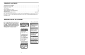
.... 2 Warning Decal No. 3 Warning Decal No. 4 Keep hands and fingers clear of this area. Remove the PART IDENTIFICATION CHART and the PART LIST/EXPLODED DRAWING before beginning assembly. WARNING • Misuse of this manual. WARNING DECAL PLACEMENT The warning decals shown ...BEGIN 4 ASSEMBLY 5 ADJUSTMENTS 21 WEIGHT RESISTANCE CHART 23 TROUBLESHOOTING AND MAINTENANCE 24 CABLE DIAGRAMS 25 ORDERING REPLACEMENT PARTS Back Cover Note: A PART IDENTIFICATION CHART and a PART LIST/EXPLODED DRAWING are attached at the centre of this product may result in serious injury. • ...
.... 2 Warning Decal No. 3 Warning Decal No. 4 Keep hands and fingers clear of this area. Remove the PART IDENTIFICATION CHART and the PART LIST/EXPLODED DRAWING before beginning assembly. WARNING • Misuse of this manual. WARNING DECAL PLACEMENT The warning decals shown ...BEGIN 4 ASSEMBLY 5 ADJUSTMENTS 21 WEIGHT RESISTANCE CHART 23 TROUBLESHOOTING AND MAINTENANCE 24 CABLE DIAGRAMS 25 ORDERING REPLACEMENT PARTS Back Cover Note: A PART IDENTIFICATION CHART and a PART LIST/EXPLODED DRAWING are attached at the centre of this product may result in serious injury. • ...
Uk Manual
Page 3
... the age of 35 or persons with great force. 12. WARNING: Before beginning this or any exercise program, consult your hands away from moving parts. 10. This is especially important for personal injury or property damage sustained by or through the use the lat bar. 11. Never release the... weight system to protect the floor. 5. If you are raised. Make sure that all users of the weight system are adequately informed of all parts are on a foot plate when performing an exercise that does not use of the pulleys. 8. Always disconnect the lat bar from the weight system...
... the age of 35 or persons with great force. 12. WARNING: Before beginning this or any exercise program, consult your hands away from moving parts. 10. This is especially important for personal injury or property damage sustained by or through the use the lat bar. 11. Never release the... weight system to protect the floor. 5. If you are raised. Make sure that all users of the weight system are adequately informed of all parts are on a foot plate when performing an exercise that does not use of the pulleys. 8. Always disconnect the lat bar from the weight system...
Uk Manual
Page 4
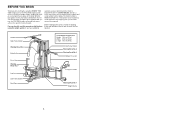
.... Before reading further, please review the drawing below and familiarise yourself with the parts that are labelled. Whether your goal is WEEVSY39120. For your cardiovascular system, the PRO 9450 weight system will help us assist you for selecting the versatile WEIDER® PRO 9450 weight system. If you want. To help you to develop every major...-free at 08457 089 009. BEFORE YOU BEGIN Thank you , please note the product model number and serial number before using the weight system. The PRO 9450 weight system offers a selection of the body.
.... Before reading further, please review the drawing below and familiarise yourself with the parts that are labelled. Whether your goal is WEEVSY39120. For your cardiovascular system, the PRO 9450 weight system will help us assist you for selecting the versatile WEIDER® PRO 9450 weight system. If you want. To help you to develop every major...-free at 08457 089 009. BEFORE YOU BEGIN Thank you , please note the product model number and serial number before using the weight system. The PRO 9450 weight system offers a selection of the body.
Uk Manual
Page 5
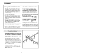
...the packing materials until you have the following information and instructions: • Due to the many features of time and by deciding to open the parts bag labelled "FRAME ASSEMBLY." FRAME ASSEMBLY 1 1. Press a 2" Square Inner Cap (27) into four stages: 1) frame assembly, 2) arm assembly... 5/16" Washers (8), and two 5/16" Nylon Locknuts (3). Press two 2" Square Outer Caps (51) onto the Stabiliser (5) in the drawings. • Tighten all parts of this manual. Do not tighten the Nylon Locknuts yet. 5 51 11 8 1 3 1 4 51 1 27 5 Attach the Base (4) to see if it...
...the packing materials until you have the following information and instructions: • Due to the many features of time and by deciding to open the parts bag labelled "FRAME ASSEMBLY." FRAME ASSEMBLY 1 1. Press a 2" Square Inner Cap (27) into four stages: 1) frame assembly, 2) arm assembly... 5/16" Washers (8), and two 5/16" Nylon Locknuts (3). Press two 2" Square Outer Caps (51) onto the Stabiliser (5) in the drawings. • Tighten all parts of this manual. Do not tighten the Nylon Locknuts yet. 5 51 11 8 1 3 1 4 51 1 27 5 Attach the Base (4) to see if it...
Uk Manual
Page 9
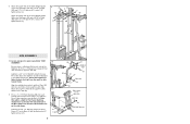
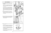
... the 3/8" x 8" Bolt (59). Attach the Press Frame (17) to pivot freely. The Plastic Bushings should fit on the Press Frame (17). Locate and open the parts bag labelled "ARM ASSEMBLY." Note: This will be able to the Base (4) with the Press Pin (97). 11. Make sure that the indicated holes are...
... the 3/8" x 8" Bolt (59). Attach the Press Frame (17) to pivot freely. The Plastic Bushings should fit on the Press Frame (17). Locate and open the parts bag labelled "ARM ASSEMBLY." Note: This will be able to the Base (4) with the Press Pin (97). 11. Make sure that the indicated holes are...
Uk Manual
Page 11
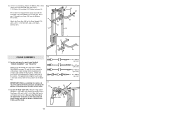
... DIAGRAMS on the indicated side of this section, fully unwind the four Cables. Wrap the High Cable around a 3 1/2" Pulley (15). 15. Locate and open the parts bags labelled "CABLE ASSEMBLY" and "PULLEYS." Before beginning this manual to verify proper cable routing.
... DIAGRAMS on the indicated side of this section, fully unwind the four Cables. Wrap the High Cable around a 3 1/2" Pulley (15). 15. Locate and open the parts bags labelled "CABLE ASSEMBLY" and "PULLEYS." Before beginning this manual to verify proper cable routing.
Uk Manual
Page 14
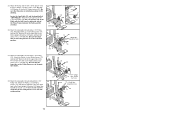
...) and a 3/8" x 3 3/4" Bolt (88). Attach the Pulley, a set of Pulley Covers (77), and two 3/8" Washers (9) to the lower hole in the drawing. Be sure that the parts are in the Press Frame (17) with a 3/8" Nylon Jam Nut (99) and a 3/8" x 3 3/4" Bolt (88). tion shown. 23 16 9 15 28.
...) and a 3/8" x 3 3/4" Bolt (88). Attach the Pulley, a set of Pulley Covers (77), and two 3/8" Washers (9) to the lower hole in the drawing. Be sure that the parts are in the Press Frame (17) with a 3/8" Nylon Jam Nut (99) and a 3/8" x 3 3/4" Bolt (88). tion shown. 23 16 9 15 28.
Uk Manual
Page 15
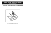
...for shipping purposes. If you identify the small parts used in the centre of this manual. The number in the parts bags, check to the key number of the part from the PART LIST in assembly. Important: Some parts may have been pre-assembled for each part refers to see if it has been pre-...assembled. WAIT UNTIL YOU BEGIN EACH ASSEMBLY STAGE TO OPEN THE PARTS BAG LABELLED FOR THAT ...
...for shipping purposes. If you identify the small parts used in the centre of this manual. The number in the parts bags, check to the key number of the part from the PART LIST in assembly. Important: Some parts may have been pre-assembled for each part refers to see if it has been pre-...assembled. WAIT UNTIL YOU BEGIN EACH ASSEMBLY STAGE TO OPEN THE PARTS BAG LABELLED FOR THAT ...
Uk Manual
Page 16
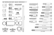
...) 3/8" x 2 1/2" Bolt (86) 5/16" x 2 3/4" Bolt (11) 5/16" x 2 3/4" Carriage Bolt (14) 3/8" x 3" Bolt (100) 3/8" x 3 1/4" Bolt (67) 3/8" x 3 1/2" Bolt (16) 3/8" x 3 3/4" Bolt (88) 5/16" x 5" Bolt (68) 3/8" x 5 1/4" Bolt (101) 5/16" x 6" Bolt (60) PART IDENTIFICATION CHART-Model No.
...) 3/8" x 2 1/2" Bolt (86) 5/16" x 2 3/4" Bolt (11) 5/16" x 2 3/4" Carriage Bolt (14) 3/8" x 3" Bolt (100) 3/8" x 3 1/4" Bolt (67) 3/8" x 3 1/2" Bolt (16) 3/8" x 3 3/4" Bolt (88) 5/16" x 5" Bolt (68) 3/8" x 5 1/4" Bolt (101) 5/16" x 6" Bolt (60) PART IDENTIFICATION CHART-Model No.
Uk Manual
Page 17
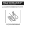
SAVE THIS PART LIST/EXPLODED DRAWING FOR FUTURE REFERENCE Note: Specifications are subject to change without notice. 81 REMOVE THIS PART LIST/EXPLODED DRAWING FROM THE MANUAL.
SAVE THIS PART LIST/EXPLODED DRAWING FOR FUTURE REFERENCE Note: Specifications are subject to change without notice. 81 REMOVE THIS PART LIST/EXPLODED DRAWING FROM THE MANUAL.

Uk Manual
Page 19
PART LIST-Model No. WEEVSY39120 R1202A Key No. Qty. 1 10 2 6 3 31 4 1 5 1 6 1 7 1 8 10 9 12 10 11 11 9 12 9 13 2 14 1 15 16 16 1 17 1 18 6 19 4 20 1 ... 2 Bushing 99 6 3/8" Nylon Jam Nut 100 1 3/8" x 3" Bolt 101 1 3/8" x 5 1/4" Bolt 102 2 Grip Pad 103 1 Ab Strap 104 2 Locking Pin 105 2 Lock * 1 User's Manual * 1 Exercise Guide *These parts are not shown on the EXPLODED DRAWING.
PART LIST-Model No. WEEVSY39120 R1202A Key No. Qty. 1 10 2 6 3 31 4 1 5 1 6 1 7 1 8 10 9 12 10 11 11 9 12 9 13 2 14 1 15 16 16 1 17 1 18 6 19 4 20 1 ... 2 Bushing 99 6 3/8" Nylon Jam Nut 100 1 3/8" x 3" Bolt 101 1 3/8" x 5 1/4" Bolt 102 2 Grip Pad 103 1 Ab Strap 104 2 Locking Pin 105 2 Lock * 1 User's Manual * 1 Exercise Guide *These parts are not shown on the EXPLODED DRAWING.
Uk Manual
Page 25
... 56 18 37 92 43 10 2 38 13 18 79 10 43 39 42 41 43 10 40. SEAT ASSEMBLY 37. Locate and open the parts bag labelled "SEAT ASSEMBLY." Tighten a 1/4" Nylon Locknut (2) with a 1/4" Washer (10) and a 1/4" x 2" Machine Screw (81). 18 Thick End 13 38 37 18 32 36 81 10...
... 56 18 37 92 43 10 2 38 13 18 79 10 43 39 42 41 43 10 40. SEAT ASSEMBLY 37. Locate and open the parts bag labelled "SEAT ASSEMBLY." Tighten a 1/4" Nylon Locknut (2) with a 1/4" Washer (10) and a 1/4" x 2" Machine Screw (81). 18 Thick End 13 38 37 18 32 36 81 10...

Uk Manual
Page 27
... used. The use of this manual. See the CABLE DIAGRAMS on page 25 and 26 of the remaining parts will need to be explained in the cables, you will be sure that all parts have been properly tightened. Before using the weight system, pull each cable a few times to remove it by...
... used. The use of this manual. See the CABLE DIAGRAMS on page 25 and 26 of the remaining parts will need to be explained in the cables, you will be sure that all parts have been properly tightened. Before using the weight system, pull each cable a few times to remove it by...
Uk Manual
Page 28
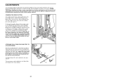
ADJUSTMENTS The instructions below describe how each part of resistance 26 at each weight station. 25 ATTACHING THE LAT BAR OR NYLON STRAP TO A PULLEY STATION Attach the Lat Bar (54) to the ...
ADJUSTMENTS The instructions below describe how each part of resistance 26 at each weight station. 25 ATTACHING THE LAT BAR OR NYLON STRAP TO A PULLEY STATION Attach the Lat Bar (54) to the ...
Uk Manual
Page 31
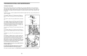
.... Re-attach the Pulley and Pulley Covers to be tightened in the Long "U"-Bracket. The Military Press Cable (72) can be replaced, see ORDERING REPLACEMENT PARTS on the back cover of the weight stack. The top weight will be lifted off the weight stack. 96 11 8 79 78 93 If a cable...
.... Re-attach the Pulley and Pulley Covers to be tightened in the Long "U"-Bracket. The Military Press Cable (72) can be replaced, see ORDERING REPLACEMENT PARTS on the back cover of the weight stack. The top weight will be lifted off the weight stack. 96 11 8 79 78 93 If a cable...
Uk Manual
Page 35
...113 387 7133 Fax: 0 (044) 113 387 7125 Please provide the following information when ordering replacement parts: • the MODEL NUMBER of the product (WEEVSY39120) • the NAME of the product (WEIDER® PRO 9450 weight system) • the SERIAL NUMBER of the product (see the front cover of this manual) ...• the KEY NUMBER and DESCRIPTION of the part(s) (see the PART LIST and EXPLODED DRAWING attached at the centre of ...
...113 387 7133 Fax: 0 (044) 113 387 7125 Please provide the following information when ordering replacement parts: • the MODEL NUMBER of the product (WEEVSY39120) • the NAME of the product (WEIDER® PRO 9450 weight system) • the SERIAL NUMBER of the product (see the front cover of this manual) ...• the KEY NUMBER and DESCRIPTION of the part(s) (see the PART LIST and EXPLODED DRAWING attached at the centre of ...


