
Uk Manual
Page 1
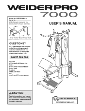
As a manufacturer, we are missing parts, please call: 08457 089 009 Or write: ICON Health & Fitness, Ltd. Save this equipment. WEEVSY6885.0 Serial No. USER'S MANUAL Serial Number Decal (Under Seat) QUESTIONS? Model No. Unit 4 Revie Road Industrial Estate Revie Road Beeston Leeds, LS118JG UK email: [email protected] CAUTION Read all precautions and instructions in the space above for future reference. If you have...
As a manufacturer, we are missing parts, please call: 08457 089 009 Or write: ICON Health & Fitness, Ltd. Save this equipment. WEEVSY6885.0 Serial No. USER'S MANUAL Serial Number Decal (Under Seat) QUESTIONS? Model No. Unit 4 Revie Road Industrial Estate Revie Road Beeston Leeds, LS118JG UK email: [email protected] CAUTION Read all precautions and instructions in the space above for future reference. If you have...
Uk Manual
Page 2
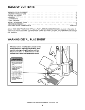
... of ICON IP, Inc. 2 If the decal is missing or illegible, please call the telephone number on the weight system in the center of this manual and order a free replacement decal. TABLE OF CONTENTS WARNING DECAL PLACEMENT 2 IMPORTANT PRECAUTIONS 3 BEFORE YOU BEGIN 4 ASSEMBLY 5 ADJUSTMENTS 14 CABLE DIAGRAM 17 WEIGHT RESISTANCE CHART 17 EXERCISE GUIDELINES 18 ORDERING REPLACEMENT PARTS Back Cover Note: A PART IDENTIFICATION CHART and a PART LIST/EXPLODED DRAWING is attached in...
... of ICON IP, Inc. 2 If the decal is missing or illegible, please call the telephone number on the weight system in the center of this manual and order a free replacement decal. TABLE OF CONTENTS WARNING DECAL PLACEMENT 2 IMPORTANT PRECAUTIONS 3 BEFORE YOU BEGIN 4 ASSEMBLY 5 ADJUSTMENTS 14 CABLE DIAGRAM 17 WEIGHT RESISTANCE CHART 17 EXERCISE GUIDELINES 18 ORDERING REPLACEMENT PARTS Back Cover Note: A PART IDENTIFICATION CHART and a PART LIST/EXPLODED DRAWING is attached in...
Uk Manual
Page 3
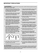
... are on the weight system before using the weight system. Always secure the weight stack with pre-existing health problems. Read all warnings on the pulleys. If the cables bind as shown in any time while exercising, stop immediately and make sure that the cables remain on page 15). 6. Never release the ankle strap, leg lever, squat bar, leg press, or handles while weights are exercising, stop immediately and...
... are on the weight system before using the weight system. Always secure the weight stack with pre-existing health problems. Read all warnings on the pulleys. If the cables bind as shown in any time while exercising, stop immediately and make sure that the cables remain on page 15). 6. Never release the ankle strap, leg lever, squat bar, leg press, or handles while weights are exercising, stop immediately and...
Uk Manual
Page 4
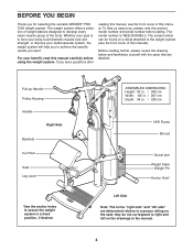
If you , please note the product model number and serial number before using the weight system. Before reading further, please review the drawing below and familiarise yourself with the parts that are determined relative to achieve the specific results you for selecting the versatile WEIDER® PRO 7000 weight system. Whether your goal is WEEVSY6885.0. ASSEMBLED DIMENSIONS: Height: 82 in. / 208 cm Width: 105 in. / 267...
If you , please note the product model number and serial number before using the weight system. Before reading further, please review the drawing below and familiarise yourself with the parts that are determined relative to achieve the specific results you for selecting the versatile WEIDER® PRO 7000 weight system. Whether your goal is WEEVSY6885.0. ASSEMBLED DIMENSIONS: Height: 82 in. / 208 cm Width: 105 in. / 267...
Uk Manual
Page 5
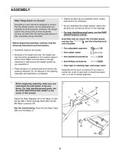
... assemble the weight system, make sure you assemble it will be require the included grease and hex key , and the following information and instructions: • Assembly requires two people. • Because of its weight and size, the weight system should be assembled in the location where it . • Place all parts as you assemble them, unless instructed to do otherwise. • As you have a socket set, a set of open...
... assemble the weight system, make sure you assemble it will be require the included grease and hex key , and the following information and instructions: • Assembly requires two people. • Because of its weight and size, the weight system should be assembled in the location where it . • Place all parts as you assemble them, unless instructed to do otherwise. • As you have a socket set, a set of open...
Uk Manual
Page 8
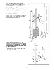
... 73 Grease 3 99 101 8 Set the Shroud (13) onto the Base (1). Engage the VKR Pin (101) into 6 the Upright (3) through the indicated holes. Attach the Bottom Cover (14) and the Shroud to the Upright (3) with two M4 x 16mm Screws (70). 3 79 78 79 78 Wide End 70 95 101 13 70 70 7. Grease the M10 x 168mm Button Bolt (99). Attach the VKR...
... 73 Grease 3 99 101 8 Set the Shroud (13) onto the Base (1). Engage the VKR Pin (101) into 6 the Upright (3) through the indicated holes. Attach the Bottom Cover (14) and the Shroud to the Upright (3) with two M4 x 16mm Screws (70). 3 79 78 79 78 Wide End 70 95 101 13 70 70 7. Grease the M10 x 168mm Button Bolt (99). Attach the VKR...
Uk Manual
Page 9
... the Press Arm (8) with four M10 x 25mm Screws (58). Attach an Eyehook (66) to the Upright (3) with the M4 x 5mm Screw (69). 11 3 74 72 4 66 66 8 58 16 30 69 58 9 Attach the Press Arm (8) without the wire to the Top Frame (4) with the other Eyehook (66). 11. Route the Press Arm Cable (30) through the Swivel Arm and the Press Arm (8) as shown. Do not tighten...
... the Press Arm (8) with four M10 x 25mm Screws (58). Attach an Eyehook (66) to the Upright (3) with the M4 x 5mm Screw (69). 11 3 74 72 4 66 66 8 58 16 30 69 58 9 Attach the Press Arm (8) without the wire to the Top Frame (4) with the other Eyehook (66). 11. Route the Press Arm Cable (30) through the Swivel Arm and the Press Arm (8) as shown. Do not tighten...
Uk Manual
Page 10
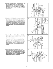
Make sure the Press Arm Cable (30) is routed under the indicated welded rods. Attach the 3 1/2" Pulley (24) and a Cable Trap (28) to a Swivel Arm (16) with an M10 x 45mm Bolt (65) and an M10 Nylon Locknut (73). Attach a "V"-pulley (22) to the Top Frame (4) with 12 an M10 x 64mm Button Bolt (75), two M10 Washers (71), two 5mm Spacers (25), and an M10...
Make sure the Press Arm Cable (30) is routed under the indicated welded rods. Attach the 3 1/2" Pulley (24) and a Cable Trap (28) to a Swivel Arm (16) with an M10 x 45mm Bolt (65) and an M10 Nylon Locknut (73). Attach a "V"-pulley (22) to the Top Frame (4) with 12 an M10 x 64mm Button Bolt (75), two M10 Washers (71), two 5mm Spacers (25), and an M10...
Uk Manual
Page 11
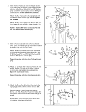
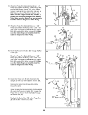
... of the Weight Tube. Route the Cable through the Top 18 Cover (15). 16. Attach the Press Arm (8) with the wire to the Weight Tube (11) with the M4 x 5mm Screw (69). 16 30 69 58 8 58 3 11 Wrap the Press Arm Cable (30) under a 3 1/2" 16 Pulley (24). Wrap the Press Arm Cable (30) over a 3 1/2" Pulley (24). Attach the Pulley and a Cable Trap (28) to the Press Arm (8) with an M10 x 48mm Bolt (62...
... of the Weight Tube. Route the Cable through the Top 18 Cover (15). 16. Attach the Press Arm (8) with the wire to the Weight Tube (11) with the M4 x 5mm Screw (69). 16 30 69 58 8 58 3 11 Wrap the Press Arm Cable (30) under a 3 1/2" 16 Pulley (24). Wrap the Press Arm Cable (30) over a 3 1/2" Pulley (24). Attach the Pulley and a Cable Trap (28) to the Press Arm (8) with an M10 x 48mm Bolt (62...
Uk Manual
Page 12
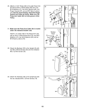
... 22 22 18 27 27 23 79 60 60 3 23. Make sure the Press Arm Cable (30) is in the groove of the Pulley. 21. Make sure the Press Arm Cable (30) is routed under the indicated welded rods. Attach a 2 3/4" Pulley (23) to the Upright (3) with an M10 x 53mm Button Bolt (61), two M10 Washers (71), two 5mm Spacers (25), two Finger Guards...
... 22 22 18 27 27 23 79 60 60 3 23. Make sure the Press Arm Cable (30) is in the groove of the Pulley. 21. Make sure the Press Arm Cable (30) is routed under the indicated welded rods. Attach a 2 3/4" Pulley (23) to the Upright (3) with an M10 x 53mm Button Bolt (61), two M10 Washers (71), two 5mm Spacers (25), two Finger Guards...
Uk Manual
Page 13
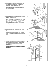
... the VKR Frame (82). 27 Attach the Arm Pad and Base to the Leg Lever (7) with two M6 x 63mm Screws (103) and two M6 Washers (78). 24. the Leg Lever must be able to an M10 x 71mm Bolt (67). Hook the Seat Frame (6) onto the Upright (3) at the indicated location. 6 78 60 68 25. ...step on the other side of the VKR Frame (82). 3 21 21 103 84 78 103 82 13 Grease 6 67 73 7 70 49 26. Attach the Seat (19) to the Seat Frame (6) with 24 two M6 x 25mm Screws (60), an M6 x 77mm 19 Screw (68), and an M6 Washer (78). Attach the Leg Lever (7) to the Seat Frame (6) with the Bolt...
... the VKR Frame (82). 27 Attach the Arm Pad and Base to the Leg Lever (7) with two M6 x 63mm Screws (103) and two M6 Washers (78). 24. the Leg Lever must be able to an M10 x 71mm Bolt (67). Hook the Seat Frame (6) onto the Upright (3) at the indicated location. 6 78 60 68 25. ...step on the other side of the VKR Frame (82). 3 21 21 103 84 78 103 82 13 Grease 6 67 73 7 70 49 26. Attach the Seat (19) to the Seat Frame (6) with 24 two M6 x 25mm Screws (60), an M6 x 77mm 19 Screw (68), and an M6 Washer (78). Attach the Leg Lever (7) to the Seat Frame (6) with the Bolt...

Uk Manual
Page 14
... accompanying exercise guide to see the correct form for important information about how to the end of the Press Arm Cable (30) with a Cable Clip (37). The weight system can be cleaned with 28 two M6 x 25mm Screws (60). 87 29. See the inset drawing A. To use solvents. Do not use the leg lever (not shown), hook the Pulley Housings (32) to adjust the weight system...
... accompanying exercise guide to see the correct form for important information about how to the end of the Press Arm Cable (30) with a Cable Clip (37). The weight system can be cleaned with 28 two M6 x 25mm Screws (60). 87 29. See the inset drawing A. To use solvents. Do not use the leg lever (not shown), hook the Pulley Housings (32) to adjust the weight system...
Uk Manual
Page 15
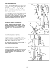
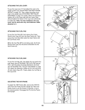
... be attached to the Press Arm Cable (30) in the same manner. CHANGING THE WEIGHT SETTING To change the setting of the Seat Frame (6), or to remove it aside. See the WEIGHT RESISTANCE CHART on page 14). Turn the bent end down. ADJUSTING THE SEAT FRAME HEIGHT To adjust the height of a weight stack, insert the Weight Pin (55) under the desired Weight (17). ATTACHING THE HANDLES To attach a Handle (33), first attach the pulley housings...
... be attached to the Press Arm Cable (30) in the same manner. CHANGING THE WEIGHT SETTING To change the setting of the Seat Frame (6), or to remove it aside. See the WEIGHT RESISTANCE CHART on page 14). Turn the bent end down. ADJUSTING THE SEAT FRAME HEIGHT To adjust the height of a weight stack, insert the Weight Pin (55) under the desired Weight (17). ATTACHING THE HANDLES To attach a Handle (33), first attach the pulley housings...
Uk Manual
Page 16
... Seat Frame with only one Extension Cable attached to the weight system (see ATTACHING THE CURL PAD above). Move the Frame down to use the Frame to exercise, or up to the Leg Lever with two Cable Clips (37) and attach the Chain to the stored position. ADJUSTING THE VKR FRAME To adjust the VKR Frame (82), remove the VKR Pin (101) from the Seat Frame (6). ATTACHING...
... Seat Frame with only one Extension Cable attached to the weight system (see ATTACHING THE CURL PAD above). Move the Frame down to use the Frame to exercise, or up to the Leg Lever with two Cable Clips (37) and attach the Chain to the stored position. ADJUSTING THE VKR FRAME To adjust the VKR Frame (82), remove the VKR Pin (101) from the Seat Frame (6). ATTACHING...
Uk Manual
Page 17
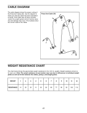
... 86 95 102 110 17 CABLE DIAGRAM The cable diagram shows the proper routing of the Press Arm Cable (30). Note: The actual resistance at each arm. The numbers show the correct route for the 12.5 lb. Press Arm Cable (30) 7 6 4 3 9 8 5 2 1 WEIGHT RESISTANCE CHART The chart below shows the approximate weight resistance for the Cable. Use the diagram to differences in individual weight plates as well as friction between the cables, pulleys, and weight guides. weights. Weight resistance shown is for each...
... 86 95 102 110 17 CABLE DIAGRAM The cable diagram shows the proper routing of the Press Arm Cable (30). Note: The actual resistance at each arm. The numbers show the correct route for the 12.5 lb. Press Arm Cable (30) 7 6 4 3 9 8 5 2 1 WEIGHT RESISTANCE CHART The chart below shows the approximate weight resistance for the Cable. Use the diagram to differences in individual weight plates as well as friction between the cables, pulleys, and weight guides. weights. Weight resistance shown is for each...
Uk Manual
Page 18
... capacity. You can complete 3 sets of 12 repetitions without difficulty, increase the amount of weight. formed. (A "repetition" is important to avoid overdoing it . Work your breath. 18 To give your body time to regenerate. The repetitions in each set . Your muscles will adapt and grow as possible without pausing. Weight Loss To lose weight, use a low amount of weight and increase the number...
... capacity. You can complete 3 sets of 12 repetitions without difficulty, increase the amount of weight. formed. (A "repetition" is important to avoid overdoing it . Work your breath. 18 To give your body time to regenerate. The repetitions in each set . Your muscles will adapt and grow as possible without pausing. Weight Loss To lose weight, use a low amount of weight and increase the number...
Uk Manual
Page 19
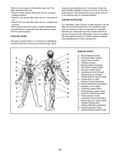
... effective way to make exercise a regular and enjoyable part of thigh) J. Sternomastoid (neck) B. Pectoralis Major (chest) C. Brachioradials (forearm) F. Abductor (outer thigh) H. Anterior Deltoid (shoulder) M. Hamstring (back of sets and repetitions completed. List the date, the exercises performed, the resistance used, and the numbers of leg) X. Rhomboideus (upper back) Q. Gastrocnemius (back of every month. Record your arms and legs. Hip Flexors (upper thigh...
... effective way to make exercise a regular and enjoyable part of thigh) J. Sternomastoid (neck) B. Pectoralis Major (chest) C. Brachioradials (forearm) F. Abductor (outer thigh) H. Anterior Deltoid (shoulder) M. Hamstring (back of sets and repetitions completed. List the date, the exercises performed, the resistance used, and the numbers of leg) X. Rhomboideus (upper back) Q. Gastrocnemius (back of every month. Record your arms and legs. Hip Flexors (upper thigh...
Uk Manual
Page 20
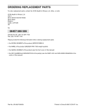
... MODEL NUMBER of the product (WEEVSY6885.0) • the NAME of the product (WEIDER PRO 7000 weight system) • the SERIAL NUMBER of the product (see the front cover of this manual) • the KEY NUMBER and DESCRIPTION of the part(s) (see the PART LIST and EXPLODED DRAWING in the centre of this manual) Part No. 231492 R0905A Printed in China © 2005 ICON IP, Inc. office, or write: ICON Health & Fitness...
... MODEL NUMBER of the product (WEEVSY6885.0) • the NAME of the product (WEIDER PRO 7000 weight system) • the SERIAL NUMBER of the product (see the front cover of this manual) • the KEY NUMBER and DESCRIPTION of the part(s) (see the PART LIST and EXPLODED DRAWING in the centre of this manual) Part No. 231492 R0905A Printed in China © 2005 ICON IP, Inc. office, or write: ICON Health & Fitness...
Uk Manual
Page 21
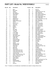
... Arm Weight Backrest Seat Pad Tube Foam Pad "V"-pulley 2 3/4" Pulley 3 1/2" Pulley 5mm Spacer Half Finger Guard Finger Guard Cable Trap Pulley Cover Press Arm Cable Extension Cable Pulley Housing Handle Extension Strap Squat Bar Pad Ankle Strap Cable Clip Base Cap Pull-up Handle M10 x 80mm Button Bolt M10 Split Washer M10 x 168mm Button Bolt Curl Knob VKR Pin 32mm Thin Round Inner Cap M6 x 63mm Screw User's Manual Exercise Guide Hex Key Note: "#" indicates a non-illustrated part. WEEVSY6885.0 R0905A Key No. PART LIST-Model...
... Arm Weight Backrest Seat Pad Tube Foam Pad "V"-pulley 2 3/4" Pulley 3 1/2" Pulley 5mm Spacer Half Finger Guard Finger Guard Cable Trap Pulley Cover Press Arm Cable Extension Cable Pulley Housing Handle Extension Strap Squat Bar Pad Ankle Strap Cable Clip Base Cap Pull-up Handle M10 x 80mm Button Bolt M10 Split Washer M10 x 168mm Button Bolt Curl Knob VKR Pin 32mm Thin Round Inner Cap M6 x 63mm Screw User's Manual Exercise Guide Hex Key Note: "#" indicates a non-illustrated part. WEEVSY6885.0 R0905A Key No. PART LIST-Model...
Uk Manual
Page 22
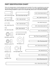
...) M8 x 89mm Bolt (64) M8 x 115mm Bolt (76) M6 x 127mm Screw (79) M10 x 168mm Button Bolt (99) Note: Some small parts may have been pre-attached. The number in parentheses by each drawing is not in the parts bag, check to identify small parts used in the center of this manual. If a part is the key number of the part, from the PART LIST in assembly. PART IDENTIFICATION CHART Refer to...
...) M8 x 89mm Bolt (64) M8 x 115mm Bolt (76) M6 x 127mm Screw (79) M10 x 168mm Button Bolt (99) Note: Some small parts may have been pre-attached. The number in parentheses by each drawing is not in the parts bag, check to identify small parts used in the center of this manual. If a part is the key number of the part, from the PART LIST in assembly. PART IDENTIFICATION CHART Refer to...


