
English Manual
Page 1
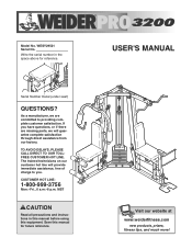
If you have questions, or if there are committed to you. MST CAUTION Read all precautions and instructions in the space above for future reference. TO AVOID DELAYS, PLEASE CALL DIRECT TO OUR TOLLFREE CUSTOMER HOT LINE. The trained technicians on our customer hot line will guarantee complete satisfaction through direct assistance from our factory. Write the serial number in this manual before using this manual for reference. CUSTOMER HOT LINE: 1-800-999-3756 Mon.-Fri., 6 a.m.-6 p.m. USER'S MANUAL Visit our website at www.weiderfitness.com new products, prizes, fitness tips, ...
If you have questions, or if there are committed to you. MST CAUTION Read all precautions and instructions in the space above for future reference. TO AVOID DELAYS, PLEASE CALL DIRECT TO OUR TOLLFREE CUSTOMER HOT LINE. The trained technicians on our customer hot line will guarantee complete satisfaction through direct assistance from our factory. Write the serial number in this manual before using this manual for reference. CUSTOMER HOT LINE: 1-800-999-3756 Mon.-Fri., 6 a.m.-6 p.m. USER'S MANUAL Visit our website at www.weiderfitness.com new products, prizes, fitness tips, ...
English Manual
Page 2
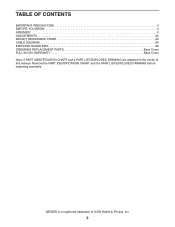
Remove the PART IDENTIFICATION CHART and the PART LIST/EXPLODED DRAWING before beginning assembly. WEIDER is a registered trademark of this manual. TABLE OF CONTENTS IMPORTANT PRECAUTIONS 3 BEFORE YOU BEGIN 4 ASSEMBLY 5 ADJUSTMENTS 20 WEIGHT RESISTANCE CHART 23 CABLE DIAGRAM 24 EXERCISE GUIDELINES 26 ORDERING REPLACEMENT PARTS Back Cover FULL 90 DAY WARRANTY Back Cover Note: A PART IDENTIFICATION CHART and a PART LIST/EXPLODED DRAWING are attached in the center of ICON Health & Fitness, Inc. 2
Remove the PART IDENTIFICATION CHART and the PART LIST/EXPLODED DRAWING before beginning assembly. WEIDER is a registered trademark of this manual. TABLE OF CONTENTS IMPORTANT PRECAUTIONS 3 BEFORE YOU BEGIN 4 ASSEMBLY 5 ADJUSTMENTS 20 WEIGHT RESISTANCE CHART 23 CABLE DIAGRAM 24 EXERCISE GUIDELINES 26 ORDERING REPLACEMENT PARTS Back Cover FULL 90 DAY WARRANTY Back Cover Note: A PART IDENTIFICATION CHART and a PART LIST/EXPLODED DRAWING are attached in the center of ICON Health & Fitness, Inc. 2

English Manual
Page 3
If a decal is the responsibility of the owner to ensure that all users of the weight system are adequately informed of 35 or persons with great force. 14. Apply the replacement decal in this area. It is missing or illegible, please call our Customer Service Department toll-free at all times. 7. Make sure all precautions. 12. Always wear athletic shoes for persons over the age of all parts are exercising, stop immediately and begin cooling down. 15. the weights will fall with pre-existing health problems. Read all instructions in this manual and in the ...
If a decal is the responsibility of the owner to ensure that all users of the weight system are adequately informed of 35 or persons with great force. 14. Apply the replacement decal in this area. It is missing or illegible, please call our Customer Service Department toll-free at all times. 7. Make sure all precautions. 12. Always wear athletic shoes for persons over the age of all parts are exercising, stop immediately and begin cooling down. 15. the weights will fall with pre-existing health problems. Read all instructions in this manual and in the ...

English Manual
Page 4
... system offers a selection of this manual). For your cardiovascular system, the weight system will help us assist you for selecting the versatile WEIDER® PRO 3200 weight system. until 6 p.m. Before reading further, please review the drawing below and familiarize yourself with the parts that are determined relative to a person facing away ...
... system offers a selection of this manual). For your cardiovascular system, the weight system will help us assist you for selecting the versatile WEIDER® PRO 3200 weight system. until 6 p.m. Before reading further, please review the drawing below and familiarize yourself with the parts that are determined relative to a person facing away ...
English Manual
Page 5
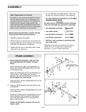
Press two 50mm Square Inner Caps (33) into the Left Base (2). Insert four M10 x 65mm Carriage Bolts (57) up into the Right Base (1). 2. ASSEMBLY Make Things Easier for assembly: • two adjustable wrenches • one rubber mallet • one standard screwdriver • one Phillips screwdriver • lubricant, such as shown in the drawings. • For help identifying small parts, use the PART IDENTIFICATION CHART. Attach the Center Base (67) to the Right Base (1) with three M10 x 70mm Bolts (81), three M10 Washers (75), and three M10 Nylon Locknuts (70). ...
Press two 50mm Square Inner Caps (33) into the Left Base (2). Insert four M10 x 65mm Carriage Bolts (57) up into the Right Base (1). 2. ASSEMBLY Make Things Easier for assembly: • two adjustable wrenches • one rubber mallet • one standard screwdriver • one Phillips screwdriver • lubricant, such as shown in the drawings. • For help identifying small parts, use the PART IDENTIFICATION CHART. Attach the Center Base (67) to the Right Base (1) with three M10 x 70mm Bolts (81), three M10 Washers (75), and three M10 Nylon Locknuts (70). ...

English Manual
Page 6
Attach the Left Upright (7) to the Left Base (2) with the two indicated M10 x 65mm Carriage Bolts (57) and two M10 Nylon Locknuts (70). 6 Do not tighten the M10 Nylon Locknuts (70) yet. 22 73 70 70 70 70 57 1 57 6 Attach the Right Upright (6) to the Left Base (2) with the two indicated M10 x 65mm Carriage Bolts (57) and two M10 Nylon Locknuts (70). Be sure the large upper hole in the Left Leg is on the side shown. Press a 50mm x 70mm Inner Cap (22) into the 4 top of the Right Leg (73). Attach the Left Leg (36) to the Right Base (1) with the two indicated M10 x 65mm Carriage ...
Attach the Left Upright (7) to the Left Base (2) with the two indicated M10 x 65mm Carriage Bolts (57) and two M10 Nylon Locknuts (70). 6 Do not tighten the M10 Nylon Locknuts (70) yet. 22 73 70 70 70 70 57 1 57 6 Attach the Right Upright (6) to the Left Base (2) with the two indicated M10 x 65mm Carriage Bolts (57) and two M10 Nylon Locknuts (70). Be sure the large upper hole in the Left Leg is on the side shown. Press a 50mm x 70mm Inner Cap (22) into the 4 top of the Right Leg (73). Attach the Left Leg (36) to the Right Base (1) with the two indicated M10 x 65mm Carriage ...

English Manual
Page 7
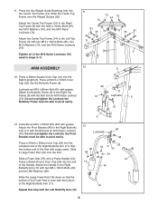
Orient the Right Seat Frame (5) with two M10 x 85mm Bolts (60), two M10 Washers (75), and two M10 Nylon Locknuts (70). Attach the Left Seat Frame (29) to the Right Upright (6) with the short side of the Left Seat Frame (29). Press a 50mm Square Inner Cap (33) into the holes. Set two Weight Bumpers (83) over the indicated holes in the Center Base (67). Attach the Right Seat Frame (5) to the Left Leg (36) with two M10 x 85mm Bolts (60), two M10 Washers (75), and two M10 Nylon Locknuts (70). Attach the Left Seat Frame (29) to the Right Leg (73) with two M10 x 65mm ...
Orient the Right Seat Frame (5) with two M10 x 85mm Bolts (60), two M10 Washers (75), and two M10 Nylon Locknuts (70). Attach the Left Seat Frame (29) to the Right Upright (6) with the short side of the Left Seat Frame (29). Press a 50mm Square Inner Cap (33) into the holes. Set two Weight Bumpers (83) over the indicated holes in the Center Base (67). Attach the Right Seat Frame (5) to the Left Leg (36) with two M10 x 85mm Bolts (60), two M10 Washers (75), and two M10 Nylon Locknuts (70). Attach the Left Seat Frame (29) to the Right Leg (73) with two M10 x 65mm ...

English Manual
Page 8
Slide the eight Weights (72) onto the Weight 8 Guides (20) with the pin grooves on the bottom. 20 74 Pin Groove Lubricate Holes 82 32 72 9. Lubricate the indicated holes in the stack of the Weight Tube (82). Press two 50mm x 70mm Inner Caps (22) into the bottom of Weights (72). Be sure the Weight Tube is oriented as shown. Do not tighten the Locknuts yet. 9 22 3 59 21 70 22 70 7 10. Attach the Right Top Frame (8) to the Right Upright (6) with two M10 x 90mm Bolts (59), a Support Plate (21), and two M10 Nylon Locknuts (70). Press the Weight Tube Bumper (32) into...
Slide the eight Weights (72) onto the Weight 8 Guides (20) with the pin grooves on the bottom. 20 74 Pin Groove Lubricate Holes 82 32 72 9. Lubricate the indicated holes in the stack of the Weight Tube (82). Press two 50mm x 70mm Inner Caps (22) into the bottom of Weights (72). Be sure the Weight Tube is oriented as shown. Do not tighten the Locknuts yet. 9 22 3 59 21 70 22 70 7 10. Attach the Right Top Frame (8) to the Right Upright (6) with two M10 x 90mm Bolts (59), a Support Plate (21), and two M10 Nylon Locknuts (70). Press the Weight Tube Bumper (32) into...
English Manual
Page 9
Lubricate an M10 x 80mm Bolt (61) with grease. the Butterfly Frame must be able to pivot easily. 22 41 70 Lubricate 6 61 9 13. Lubricate an M10 x 50mm Bolt (62) with grease. Slide a Large Foam Pad (19) onto the Arm. Slide a Foam Grip (76) onto a Press Handle (12). 11. Repeat this step with the Bolt and an M10 Nylon Locknut (70). Press a 50mm x 70mm Inner Cap (22) into the Right Upright (6). Do not overtighten the Locknut; Attach the Pivot Bracket (48) to the Left Top Frame (3) with the bottom of the Foam Pad is even with two M10 x 70mm Bolts (81), two ...
Lubricate an M10 x 80mm Bolt (61) with grease. the Butterfly Frame must be able to pivot easily. 22 41 70 Lubricate 6 61 9 13. Lubricate an M10 x 50mm Bolt (62) with grease. Slide a Large Foam Pad (19) onto the Arm. Slide a Foam Grip (76) onto a Press Handle (12). 11. Repeat this step with the Bolt and an M10 Nylon Locknut (70). Press a 50mm x 70mm Inner Cap (22) into the Right Upright (6). Do not overtighten the Locknut; Attach the Pivot Bracket (48) to the Left Top Frame (3) with the bottom of the Foam Pad is even with two M10 x 70mm Bolts (81), two ...
English Manual
Page 10
Attach the Leg Press Frame (30) to the Left Base (2) with grease. the Leg Press Frame must be able to the Butterfly Frame (9) with grease. Lubricate an M10 x 80mm Button Head Bolt (97) and both sides of the Leg Press Frame (30). Do not overtighten the Locknut; Be sure the indented sides of the Leg Lever (4). Press two 40mm x 50mm Inner Caps (23) into the 16 top of two Plastic Washers (55) with the Bolt and an M10 Nylon Locknut (70). Lubricate an M10 x 80mm Bolt (61) with the Bolt, the two Plastic 14 Lubricate 97 Welded Bushing 55 54 Washers, two Butterfly Caps (54),...
Attach the Leg Press Frame (30) to the Left Base (2) with grease. the Leg Press Frame must be able to the Butterfly Frame (9) with grease. Lubricate an M10 x 80mm Button Head Bolt (97) and both sides of the Leg Press Frame (30). Do not overtighten the Locknut; Be sure the indented sides of the Leg Lever (4). Press two 40mm x 50mm Inner Caps (23) into the 16 top of two Plastic Washers (55) with the Bolt and an M10 Nylon Locknut (70). Lubricate an M10 x 80mm Bolt (61) with the Bolt, the two Plastic 14 Lubricate 97 Welded Bushing 55 54 Washers, two Butterfly Caps (54),...

English Manual
Page 11
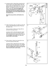
the pulleys must be necessary to loosen the indicated M10 Nylon Locknuts (70). Attach the Pulley and a Cable Trap (91) inside the Top Frame with an M10 x 45mm Bolt (66) and an M10 Nylon Locknut (70). 17 38 3 75 70 34 34 81 75 45 18 91 38 34 75 81 70 75 34 45 3 70 19 45 38 70 66 56 20. Note: To complete this step is turned to the single hole side of the weight system, with the Left Top Frame (3) removed for proper cable routing. Note: The following drawings are shown from 20 the left side of the Adjustable Double "U"-Bracket (56) with an M10 x 70mm Bolt (...
the pulleys must be necessary to loosen the indicated M10 Nylon Locknuts (70). Attach the Pulley and a Cable Trap (91) inside the Top Frame with an M10 x 45mm Bolt (66) and an M10 Nylon Locknut (70). 17 38 3 75 70 34 34 81 75 45 18 91 38 34 75 81 70 75 34 45 3 70 19 45 38 70 66 56 20. Note: To complete this step is turned to the single hole side of the weight system, with the Left Top Frame (3) removed for proper cable routing. Note: The following drawings are shown from 20 the left side of the Adjustable Double "U"-Bracket (56) with an M10 x 70mm Bolt (...

English Manual
Page 12
Attach the end of the High Cable (45) to the Weight Tube (82) with an M8 x 45mm Bolt (69) and an M8 Nylon Locknut (71). Note: Do not completely tighten the Nylon Locknut; Do not overtighten the Locknut; Attach the Small "U"-Bracket (79) to the Small "U"-Bracket (79) with aM10 x 70mm Bolt (81), two M10 Washers (75), two Long Spacers (80), and an M10 Nylon Locknut (70). 24. Attach the Pulley inside the Leg Press Frame (30) with an M10 x 45mm Bolt (66) and an M10 Nylon Locknut (70). 70 14 45 38 22. Attach the Pulley at the forward hole, inside the Left Leg (36) with an M8 Washer (...
Attach the end of the High Cable (45) to the Weight Tube (82) with an M8 x 45mm Bolt (69) and an M8 Nylon Locknut (71). Note: Do not completely tighten the Nylon Locknut; Do not overtighten the Locknut; Attach the Small "U"-Bracket (79) to the Small "U"-Bracket (79) with aM10 x 70mm Bolt (81), two M10 Washers (75), two Long Spacers (80), and an M10 Nylon Locknut (70). 24. Attach the Pulley inside the Leg Press Frame (30) with an M10 x 45mm Bolt (66) and an M10 Nylon Locknut (70). 70 14 45 38 22. Attach the Pulley at the forward hole, inside the Left Leg (36) with an M8 Washer (...
English Manual
Page 13
Attach the Pulley inside the bracket on the Left Butterfly Arm (10) with an M8 Washer (26) and an M8 Nylon Locknut (71). ly tighten the Locknut; Wrap the Cable around a 90mm 26 Pulley (38). Locate the Butterfly Cable (46). Attach the 28 Cable to the 27 "U"-Bracket (85) with an M8 x 16mm Shoulder Bolt (78) and an M8 Nylon Locknut (71). 71 46 48 78 10 13 Wrap the Leg Press Cable (95) around a 90mm Pulley (38). Attach the end of the Cable, as shown. Note: Do not complete- Route the Leg Press Cable (95) through the Left 25 Leg (36) and the Left Upright (7)...
Attach the Pulley inside the bracket on the Left Butterfly Arm (10) with an M8 Washer (26) and an M8 Nylon Locknut (71). ly tighten the Locknut; Wrap the Cable around a 90mm 26 Pulley (38). Locate the Butterfly Cable (46). Attach the 28 Cable to the 27 "U"-Bracket (85) with an M8 x 16mm Shoulder Bolt (78) and an M8 Nylon Locknut (71). 71 46 48 78 10 13 Wrap the Leg Press Cable (95) around a 90mm Pulley (38). Attach the end of the Cable, as shown. Note: Do not complete- Route the Leg Press Cable (95) through the Left 25 Leg (36) and the Left Upright (7)...

English Manual
Page 14
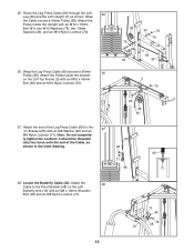
Be sure the Cable Trap is turned to the bracket on the Right Butterfly Arm (11) with an M10 x 45mm Bolt (66) and an M10 Nylon Locknut (70). 46 38 31. Wrap the Butterfly Cable (46) around a "V"-Pulley 31 (39). Attach the Pulley to hold the Cable in the groove of the Pulley. 32. Attach the Butterfly Cable (46) to the bracket on the Right Upright (6) with an M10 x 60mm Bolt (65) and an M10 Nylon Locknut (70). Bracket (103) with 32 an M8 x 16mm Shoulder Bolt (78) and an M8 Nylon Locknut (71). 66 70 103 65 40 46 39 6 70 78 46 11 48 71 14 Attach the Pulley and a ...
Be sure the Cable Trap is turned to the bracket on the Right Butterfly Arm (11) with an M10 x 45mm Bolt (66) and an M10 Nylon Locknut (70). 46 38 31. Wrap the Butterfly Cable (46) around a "V"-Pulley 31 (39). Attach the Pulley to hold the Cable in the groove of the Pulley. 32. Attach the Butterfly Cable (46) to the bracket on the Right Upright (6) with an M10 x 60mm Bolt (65) and an M10 Nylon Locknut (70). Bracket (103) with 32 an M8 x 16mm Shoulder Bolt (78) and an M8 Nylon Locknut (71). 66 70 103 65 40 46 39 6 70 78 46 11 48 71 14 Attach the Pulley and a ...

English Manual
Page 15
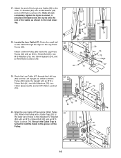
Attach a 90mm Pulley (38) inside the Right Leg (73) with an M10 x 25mm Shoulder Bolt (99) and an M10 Nylon Locknut (70). 33 4 70 73 34. Attach the Pulley and a Cable Trap (91) to the Double "U"Bracket (103) with an M10 x 95mm Bolt (98), an M10 Washers (75), and an M10 Nylon Locknut (70). Attach the Pulley to the Right Upright (6) with an M10 x 45mm Bolt (66) and an M10 Nylon Locknut (70). 96 99 34 70 75 34 35 73 38 75 34 81 6 70 75 96 91 38 98 36 70 66 103 38 96 15 Wrap the Leg Lever Cable (96) around a 90mm Pulley (38). 33. Wrap the Leg Lever Cable (96) around...
Attach a 90mm Pulley (38) inside the Right Leg (73) with an M10 x 25mm Shoulder Bolt (99) and an M10 Nylon Locknut (70). 33 4 70 73 34. Attach the Pulley and a Cable Trap (91) to the Double "U"Bracket (103) with an M10 x 95mm Bolt (98), an M10 Washers (75), and an M10 Nylon Locknut (70). Attach the Pulley to the Right Upright (6) with an M10 x 45mm Bolt (66) and an M10 Nylon Locknut (70). 96 99 34 70 75 34 35 73 38 75 34 81 6 70 75 96 91 38 98 36 70 66 103 38 96 15 Wrap the Leg Lever Cable (96) around a 90mm Pulley (38). 33. Wrap the Leg Lever Cable (96) around...
English Manual
Page 16
Note: Do not completely tighten the Nylon Locknut; it should be threaded only two turns onto the end of the Leg Lever Cable (96) to the 37 other "U"-Bracket (85) with an M10 x 50mm Bolt (62) and an M10 Nylon Locknut (70). Attach a 90mm Pulley (38) inside the Upright with an M10 x 70mm Bolt (81), two M10 Washers (75), two 13mm Spacers (34), and an M10 Nylon Locknut (70). 96 26 71 85 96 71 38 34 81 75 30 34 70 75 Cage 47 39. Route the Low Cable (47) through the cage on the Leg Press Frame (30). Wrap the Low Cable (47) around a 90mm Pulley 40 (38). Attach the end of the ...
Note: Do not completely tighten the Nylon Locknut; it should be threaded only two turns onto the end of the Leg Lever Cable (96) to the 37 other "U"-Bracket (85) with an M10 x 50mm Bolt (62) and an M10 Nylon Locknut (70). Attach a 90mm Pulley (38) inside the Upright with an M10 x 70mm Bolt (81), two M10 Washers (75), two 13mm Spacers (34), and an M10 Nylon Locknut (70). 96 26 71 85 96 71 38 34 81 75 30 34 70 75 Cage 47 39. Route the Low Cable (47) through the cage on the Leg Press Frame (30). Wrap the Low Cable (47) around a 90mm Pulley 40 (38). Attach the end of the ...

English Manual
Page 17
Attach the Pulley to the indicated bracket on the Left Base (2) with an M10 x 50mm Bolt (62) and an M10 Nylon Locknut (70). Attach the Pulley to the second set of holes from the bottom of the Pulley. 44. Wrap the Low Cable (47) around a 90mm Pulley 41 (38). Wrap the Low Cable (47) around a 90mm Pulley 44 (38). Wrap the Low Cable (47) around a 90mm Pulley 43 (38). Attach the Pulley to hold the Cable in the groove of the Adjustable Double "U"-Bracket (56) with an M10 x 45mm Bolt (66) and an M10 Nylon Locknut (70). 42. Wrap the Low Cable (47) around a 90mm ...
Attach the Pulley to the indicated bracket on the Left Base (2) with an M10 x 50mm Bolt (62) and an M10 Nylon Locknut (70). Attach the Pulley to the second set of holes from the bottom of the Pulley. 44. Wrap the Low Cable (47) around a 90mm Pulley 41 (38). Wrap the Low Cable (47) around a 90mm Pulley 44 (38). Wrap the Low Cable (47) around a 90mm Pulley 43 (38). Attach the Pulley to hold the Cable in the groove of the Adjustable Double "U"-Bracket (56) with an M10 x 45mm Bolt (66) and an M10 Nylon Locknut (70). 42. Wrap the Low Cable (47) around a 90mm ...

English Manual
Page 18
Be sure the Cable Trap is turned to the indicated bracket on the Right Base (1) with an M10 x 100mm Bolt (84), two M10 Washers (75), and an M10 Nylon Locknut (70). Attach the Pulley and a pair of Pulley Small Covers (92) to hold the Cable in the groove of the Pulley. 70 91 38 46. Be sure the Cable Trap is turned to the Right Upright (6) with an M10 x 45mm Bolt (66) and an M10 Nylon Locknut (70). Be sure the small Tabs 75 84 tabs on the Pulley Covers are on the Upright. 92 38 47 92 6 75 70 18 Attach the Pulley and a Cable Trap (91) to hold the Cable in the ...
Be sure the Cable Trap is turned to the indicated bracket on the Right Base (1) with an M10 x 100mm Bolt (84), two M10 Washers (75), and an M10 Nylon Locknut (70). Attach the Pulley and a pair of Pulley Small Covers (92) to hold the Cable in the groove of the Pulley. 70 91 38 46. Be sure the Cable Trap is turned to the Right Upright (6) with an M10 x 45mm Bolt (66) and an M10 Nylon Locknut (70). Be sure the small Tabs 75 84 tabs on the Pulley Covers are on the Upright. 92 38 47 92 6 75 70 18 Attach the Pulley and a Cable Trap (91) to hold the Cable in the ...
English Manual
Page 19
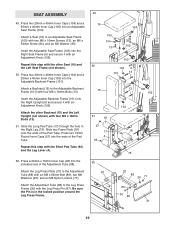
Insert the Adjustable Backrest Frame (101) into the indicated end of the Pad Tube. Slide the Long Pad Tube (17) through the hole in the locked position around the Leg Press Frame. 49 16 104 100 104 13 35 105 90 5 102 50 104 6 101 13 15 51 18 27 17 4 94 52 87 13 105 102 104 18 27 73 22 88 26 71 26 30 89 31 19 Press a 50mm x 70mm Inner Cap (22) into the Right Upright (6) and secure it with an Adjustment Knob (102). SEAT ASSEMBLY 49. Attach a Seat (16) to the Adjustable Backrest Frame (101) with the Short Pad Tube (94) and the Leg Lever (4). 52. Repeat this ...
Insert the Adjustable Backrest Frame (101) into the indicated end of the Pad Tube. Slide the Long Pad Tube (17) through the hole in the locked position around the Leg Press Frame. 49 16 104 100 104 13 35 105 90 5 102 50 104 6 101 13 15 51 18 27 17 4 94 52 87 13 105 102 104 18 27 73 22 88 26 71 26 30 89 31 19 Press a 50mm x 70mm Inner Cap (22) into the Right Upright (6) and secure it with an Adjustment Knob (102). SEAT ASSEMBLY 49. Attach a Seat (16) to the Adjustable Backrest Frame (101) with the Short Pad Tube (94) and the Leg Lever (4). 52. Repeat this ...
English Manual
Page 20
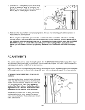
Insert the two Locking Pins (53) into the Butterfly 53 Frame (9). Do not fully tighten the Screw. 53 68 9 53 54. Do not use of the cables does not move smoothly over the pulleys. The Handle (not shown) and Ab Strap (not shown) can be attached in ADJUSTMENTS, starting position for each exercise. The use solvents. If one of all remaining parts will need to remove it by tightening the cables; See the EXERCISE GUIDELINES on page 22. Make sure all parts have been properly tightened. For some exercises, the Chain (not shown) should be performed. Before using the ...
Insert the two Locking Pins (53) into the Butterfly 53 Frame (9). Do not fully tighten the Screw. 53 68 9 53 54. Do not use of the cables does not move smoothly over the pulleys. The Handle (not shown) and Ab Strap (not shown) can be attached in ADJUSTMENTS, starting position for each exercise. The use solvents. If one of all remaining parts will need to remove it by tightening the cables; See the EXERCISE GUIDELINES on page 22. Make sure all parts have been properly tightened. For some exercises, the Chain (not shown) should be performed. Before using the ...