
User Manual
Page 1
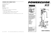
... give the following information: • The MODEL NUMBER of the product (X2-1). • The NAME of the product (WEIDER® POWERGUIDE X2 HOME GYM SYSTEM). • The SERIAL NUMBER of the product (see the front cover of this manual). • The KEY NUMBER and DESCRIPTION of the part(s) (see the PART LIST on page 18 of ICON Health & Fitness, Inc. © 1997 Printed in this user's manual before using this user's manual for future reference...
... give the following information: • The MODEL NUMBER of the product (X2-1). • The NAME of the product (WEIDER® POWERGUIDE X2 HOME GYM SYSTEM). • The SERIAL NUMBER of the product (see the front cover of this manual). • The KEY NUMBER and DESCRIPTION of the part(s) (see the PART LIST on page 18 of ICON Health & Fitness, Inc. © 1997 Printed in this user's manual before using this user's manual for future reference...
User Manual
Page 2
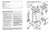
... are raised. Inspect and tighten all times. Always disconnect the lat bar from moving parts. This is especially important for inhome use of this product. 2 EXPLODED DRAWING-Model No. Never release the press arm, leg lever, lat bar, or nylon strap while weights are exercising, stop immediately and begin cooling down. 4. ICON assumes no responsibility for foot protection. 10. Remove the PART IDENTIFICATION CHART before using the home gym system. 2. X2-1 R0497A 57 27...
... are raised. Inspect and tighten all times. Always disconnect the lat bar from moving parts. This is especially important for inhome use of this product. 2 EXPLODED DRAWING-Model No. Never release the press arm, leg lever, lat bar, or nylon strap while weights are exercising, stop immediately and begin cooling down. 4. ICON assumes no responsibility for foot protection. 10. Remove the PART IDENTIFICATION CHART before using the home gym system. 2. X2-1 R0497A 57 27...
User Manual
Page 3
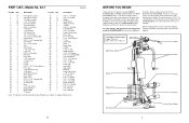
... User's Manual Note: "#" indicates a non-illustrated part. PART LIST-Model No. Qty. Specifications are labelled. If you for selecting the versatile WEIDER® POWERGUIDE X2 HOME GYM SYSTEM. The serial number can be found on a decal attached to develop every major muscle group of this manual carefully before calling. ASSEMBLED DIMENSIONS: Height: 195,6 cm Base: 162,6 cm x 170,2 cm Lat Bar High Pulley Station Press Arms Backrest Weight Stack Weight Pin Foot Plates Seat Leg Lever Low Pulley...
... User's Manual Note: "#" indicates a non-illustrated part. PART LIST-Model No. Qty. Specifications are labelled. If you for selecting the versatile WEIDER® POWERGUIDE X2 HOME GYM SYSTEM. The serial number can be found on a decal attached to develop every major muscle group of this manual carefully before calling. ASSEMBLED DIMENSIONS: Height: 195,6 cm Base: 162,6 cm x 170,2 cm Lat Bar High Pulley Station Press Arms Backrest Weight Stack Weight Pin Foot Plates Seat Leg Lever Low Pulley...
User Manual
Page 4
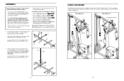
... been pre-attached. • During assembly, be sure that the Guide Tube is turned so the slot is completed. • For help identifying the small parts used in assembly, use the PART IDENTIFICATION CHART located in the centre of the Cables from the starting to ending points. The following tools: A socket set, a set of open-end or closed-end wrenches, or a set of the POWERGUIDE X2 in the...
... been pre-attached. • During assembly, be sure that the Guide Tube is turned so the slot is completed. • For help identifying the small parts used in assembly, use the PART IDENTIFICATION CHART located in the centre of the Cables from the starting to ending points. The following tools: A socket set, a set of open-end or closed-end wrenches, or a set of the POWERGUIDE X2 in the...
User Manual
Page 5
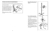
... cable used . If there is slack in step 29. 64 45 47 63 62 1 Pin Groove Round Edge 46 5. Pin 34 Groove 45 Slot 4. Do not use the home gym system. Slide the adjustment sleeve and the ball against the indicated 3 1/2" Thin Pulley (4). Slide the tenth Weight (45) onto the Weight Selector (47). TROUBLE-SHOOTING AND MAINTENANCE Inspect and tighten all parts each Nylon Wheel is turned...
... cable used . If there is slack in step 29. 64 45 47 63 62 1 Pin Groove Round Edge 46 5. Pin 34 Groove 45 Slot 4. Do not use the home gym system. Slide the adjustment sleeve and the ball against the indicated 3 1/2" Thin Pulley (4). Slide the tenth Weight (45) onto the Weight Selector (47). TROUBLE-SHOOTING AND MAINTENANCE Inspect and tighten all parts each Nylon Wheel is turned...
User Manual
Page 6
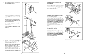
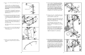
... 6 ATTACHING THE LEG LEVER TO THE LOW PULLEY STATION To use the Leg Lever (20), the seat must be performed. For some exercises, the Chain (58) should be attached between the Lat Bar and the High Cable so the Lat Bar is in this step. Do not tighten the Nylon Locknut yet. 6. Attach the Main Upright (41) to the front upright (see ATTACHING AND REMOVING THE SEAT on the Main Upright. Press a 1 1/2" Inner...
... 6 ATTACHING THE LEG LEVER TO THE LOW PULLEY STATION To use the Leg Lever (20), the seat must be performed. For some exercises, the Chain (58) should be attached between the Lat Bar and the High Cable so the Lat Bar is in this step. Do not tighten the Nylon Locknut yet. 6. Attach the Main Upright (41) to the front upright (see ATTACHING AND REMOVING THE SEAT on the Main Upright. Press a 1 1/2" Inner...
User Manual
Page 7
... changed from the weight setting. 50 SWITCHING THE PRESS ARMS TO THE PRESS MODE OR THE BUTTERFLY MODE To perform the BENCH PRESS exercise, insert the two 4 1/2" "L" Pins (61) down on the High Cable (71) so that the rubber stop is on the indicated side of the Pulley. The Press Frame must be reduced. Remove the parts from the Seat Frame (18). Refer to the cables and pulleys, the actual amount of resistance...
... changed from the weight setting. 50 SWITCHING THE PRESS ARMS TO THE PRESS MODE OR THE BUTTERFLY MODE To perform the BENCH PRESS exercise, insert the two 4 1/2" "L" Pins (61) down on the High Cable (71) so that the rubber stop is on the indicated side of the Pulley. The Press Frame must be reduced. Remove the parts from the Seat Frame (18). Refer to the cables and pulleys, the actual amount of resistance...
User Manual
Page 8
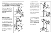
... X2 BENCH PRESS/ 200 LBS MULTI-GYM WEIGHT DECALS 12.5 LBS 125 LBS 31. Make sure that the cables move smoothly, locate and correct the problem before using the home gym system, tighten the cables (see CABLE DIAGRAMS on the Weight Bracket (62) and securely tighten the indicated 5/16" Nylon Locknut (1). 30. Wet the lower ends of the Press Arm is used. 1 62 Next, press down firmly on page 17 of the Press Arms (29). Attach...
... X2 BENCH PRESS/ 200 LBS MULTI-GYM WEIGHT DECALS 12.5 LBS 125 LBS 31. Make sure that the cables move smoothly, locate and correct the problem before using the home gym system, tighten the cables (see CABLE DIAGRAMS on the Weight Bracket (62) and securely tighten the indicated 5/16" Nylon Locknut (1). 30. Wet the lower ends of the Press Arm is used. 1 62 Next, press down firmly on page 17 of the Press Arms (29). Attach...
User Manual
Page 9
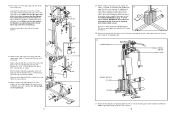
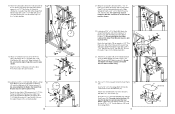
... Seat Frame (18). Re-attach the Large Pivot Bracket (52) to pivot freely. Press 3/4" Round Caps (10) into the Main Upright (41), under the indicated 3 1/2" Thin Pulley (4). 25. Attach the Eye Bolt with a 3/8" x 1 3/4" Bolt (68) and a 3/8" Nylon Locknut (2). 16 2 71 4 68 48 4 70 Route the end of the Lat Bar. 27 12 27 60 15. Hold one Pad Tube into the Leg...
... Seat Frame (18). Re-attach the Large Pivot Bracket (52) to pivot freely. Press 3/4" Round Caps (10) into the Main Upright (41), under the indicated 3 1/2" Thin Pulley (4). 25. Attach the Eye Bolt with a 3/8" x 1 3/4" Bolt (68) and a 3/8" Nylon Locknut (2). 16 2 71 4 68 48 4 70 Route the end of the Lat Bar. 27 12 27 60 15. Hold one Pad Tube into the Leg...
User Manual
Page 10
... 29 65 44 20. Attach each Seat Bracket (13). Route the Low Cable (70) on the Main Upright (41) with a 3/8" x 1 3/4" Bolt (68) and a 3/8" Jam Nut (82). Attach the other Press Arm (29) in the position shown. 21 74 73 78 41 82 22. Wrap the Low Cable (70) around a 3 1/2" Thin Pulley (4). Attach the Low Cable (70) to one of the Seat (17) must be...
... 29 65 44 20. Attach each Seat Bracket (13). Route the Low Cable (70) on the Main Upright (41) with a 3/8" x 1 3/4" Bolt (68) and a 3/8" Jam Nut (82). Attach the other Press Arm (29) in the position shown. 21 74 73 78 41 82 22. Wrap the Low Cable (70) around a 3 1/2" Thin Pulley (4). Attach the Low Cable (70) to one of the Seat (17) must be...
User Manual
Page 11
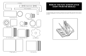
This chart is provided to help you cannot find a part in assembly. if you identify the small parts used in the parts bags, check the frame to see if it has been preassembled. Weight Bumper (40)-2 3/4" Round Cap (10)-4 1" Round Cover Cap (30)-2 1 3/4" Inner Cap (24)-6 1 1/2" Inner Cap (19)-3 5/16" Knob (15)-1 2" Outer Cap (37)-4 2" Inner Cap (36)-3 Note: Some parts may have been preassembled for shipping purposes; "J" Pin (56)-1 4" Weight Pin (50)-1 4 1/2" "L" Pin (61)-2 Plastic Bushing (79)-2 1" Round Cap (9)-4 REMOVE THIS PART IDENTIFICATION CHART FROM THE MANUAL!
This chart is provided to help you cannot find a part in assembly. if you identify the small parts used in the parts bags, check the frame to see if it has been preassembled. Weight Bumper (40)-2 3/4" Round Cap (10)-4 1" Round Cover Cap (30)-2 1 3/4" Inner Cap (24)-6 1 1/2" Inner Cap (19)-3 5/16" Knob (15)-1 2" Outer Cap (37)-4 2" Inner Cap (36)-3 Note: Some parts may have been preassembled for shipping purposes; "J" Pin (56)-1 4" Weight Pin (50)-1 4 1/2" "L" Pin (61)-2 Plastic Bushing (79)-2 1" Round Cap (9)-4 REMOVE THIS PART IDENTIFICATION CHART FROM THE MANUAL!
User Manual
Page 12
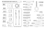
X2-1 RR00149977AA This chart is provided to the quantity used in assembly. PART IDENTIFICATION CHART-Model No. The second number refers to help you identify the small parts used in parenthesis below each part refers to the key number of the part. The number in assembly. 1/4" Jam Nut (75)-4 5/16" x 3 3/4" Bolt (49)-1 5/16" x 3 1/4" Bolt (43)-2 5/16" x 1 1/2" Fender Washer (28)-2 1/4" Nylon Locknut (3)-2 1" Retainer (8)-4 5/16" Nylon Locknut (1)-14 3/8" Flat Washer (65...
X2-1 RR00149977AA This chart is provided to the quantity used in assembly. PART IDENTIFICATION CHART-Model No. The second number refers to help you identify the small parts used in parenthesis below each part refers to the key number of the part. The number in assembly. 1/4" Jam Nut (75)-4 5/16" x 3 3/4" Bolt (49)-1 5/16" x 3 1/4" Bolt (43)-2 5/16" x 1 1/2" Fender Washer (28)-2 1/4" Nylon Locknut (3)-2 1" Retainer (8)-4 5/16" Nylon Locknut (1)-14 3/8" Flat Washer (65...


