
English Manual
Page 1
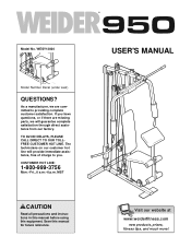
... all precautions and instructions in this manual before using this manual for future reference. TO AVOID DELAYS, PLEASE CALL DIRECT TO OUR TOLLFREE CUSTOMER HOT LINE. USER'S MANUAL Visit our website at www.weiderfitness.com new products, prizes, fitness tips, and much more! Save this equipment. As a manufacturer, we are missing parts, we will provide immediate assistance, free of charge...
... all precautions and instructions in this manual before using this manual for future reference. TO AVOID DELAYS, PLEASE CALL DIRECT TO OUR TOLLFREE CUSTOMER HOT LINE. USER'S MANUAL Visit our website at www.weiderfitness.com new products, prizes, fitness tips, and much more! Save this equipment. As a manufacturer, we are missing parts, we will provide immediate assistance, free of charge...
English Manual
Page 2
Remove the PART IDENTIFICATION CHART and the PART LIST/EXPLODED DRAWING before beginning assembly. TABLE OF CONTENTS IMPORTANT PRECAUTIONS 3 BEFORE YOU BEGIN 4 ASSEMBLY 5 ADJUSTMENTS 15 WEIGHT RESISTANCE CHART 17 CABLE DIAGRAM 18 TROUBLESHOOTING AND MAINTENANCE 19 ORDERING REPLACEMENT PARTS Back Cover LIMITED WARRANTY Back Cover Note: A PART IDENTIFICATION CHART and a PART LIST/EXPLODED DRAWING are attached in the center of ICON Health & Fitness, Inc. 2 WEIDER is a registered trademark of this manual.
Remove the PART IDENTIFICATION CHART and the PART LIST/EXPLODED DRAWING before beginning assembly. TABLE OF CONTENTS IMPORTANT PRECAUTIONS 3 BEFORE YOU BEGIN 4 ASSEMBLY 5 ADJUSTMENTS 15 WEIGHT RESISTANCE CHART 17 CABLE DIAGRAM 18 TROUBLESHOOTING AND MAINTENANCE 19 ORDERING REPLACEMENT PARTS Back Cover LIMITED WARRANTY Back Cover Note: A PART IDENTIFICATION CHART and a PART LIST/EXPLODED DRAWING are attached in the center of ICON Health & Fitness, Inc. 2 WEIDER is a registered trademark of this manual.
English Manual
Page 3
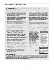
... disconnect the lat bar from moving parts. 8. If a decal is especially important for home use the weight system in the location shown. Read all times. Use the weight system only on the weight carriage. Keep hands and feet away from the weight system when performing an exercise that could cause the weight system to ensure that the cables remain on the pulleys at all instructions in the...
... disconnect the lat bar from moving parts. 8. If a decal is especially important for home use the weight system in the location shown. Read all times. Use the weight system only on the weight carriage. Keep hands and feet away from the weight system when performing an exercise that could cause the weight system to ensure that the cables remain on the pulleys at all instructions in the...
English Manual
Page 4
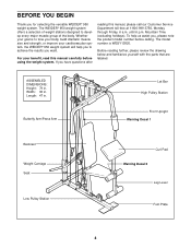
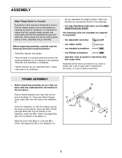
... model number is to tone your body, build dramatic muscle size and strength, or improve your benefit, read this manual, please call our Customer Service Department toll-free at 1-800-999-3756, Monday through Friday, 6 a.m. Mountain Time (excluding holidays). ASSEMBLED DIMENSIONS: Height: 79 in . If you for selecting the versatile WEIDER® 950 weight system. Butterfly Arm/Press Arm Lat Bar High Pulley Station Front Upright Warning Decal 1 Backrest Weight...
... model number is to tone your body, build dramatic muscle size and strength, or improve your benefit, read this manual, please call our Customer Service Department toll-free at 1-800-999-3756, Monday through Friday, 6 a.m. Mountain Time (excluding holidays). ASSEMBLED DIMENSIONS: Height: 79 in . If you for selecting the versatile WEIDER® 950 weight system. Butterfly Arm/Press Arm Lat Bar High Pulley Station Front Upright Warning Decal 1 Backrest Weight...
English Manual
Page 5
... realize that the versatile weight system has many parts and that by anyone. Insert two M8 x 67mm Carriage Bolts (66) into the bottom of ratchet wrenches. However, it is completed. • Tighten all parts as grease or petroleum jelly, and soapy water. Most people find that the assembly process will be assembled successfully by setting aside plenty of the...
... realize that the versatile weight system has many parts and that by anyone. Insert two M8 x 67mm Carriage Bolts (66) into the bottom of ratchet wrenches. However, it is completed. • Tighten all parts as grease or petroleum jelly, and soapy water. Most people find that the assembly process will be assembled successfully by setting aside plenty of the...
English Manual
Page 6
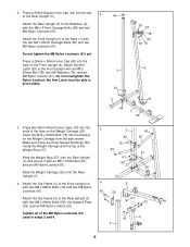
...Arm Latch must be able to the Rear Upright (3) with the M8 x 67mm Carriage Bolts (66) and two M8 Nylon Locknuts (61). Tighten all of the Weight Stop (27). Press a 50mm Square Inner Cap (44) into the ends of the Rear Upright (3). Slide the Weight Carriage (26) onto the Rear Upright (3). 4. Attach the Rear Upright (3) to the Front Upright... 65 3. Press two 25mm Round Inner Caps (43) into the top 2 of the tube on the Weight Carriage (26). 2. Make sure there are three Square Bushings (52) inside the Weight Carriage and the top of the M8 Nylon Locknuts (61) used in steps 2 and ...
...Arm Latch must be able to the Rear Upright (3) with the M8 x 67mm Carriage Bolts (66) and two M8 Nylon Locknuts (61). Tighten all of the Weight Stop (27). Press a 50mm Square Inner Cap (44) into the ends of the Rear Upright (3). Slide the Weight Carriage (26) onto the Rear Upright (3). 4. Attach the Rear Upright (3) to the Front Upright... 65 3. Press two 25mm Round Inner Caps (43) into the top 2 of the tube on the Weight Carriage (26). 2. Make sure there are three Square Bushings (52) inside the Weight Carriage and the top of the M8 Nylon Locknuts (61) used in steps 2 and ...
English Manual
Page 8
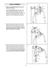
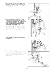
... the groove of the two Pulley Plates (14) with an M10 x 48mm Bolt (77) and an M10 Nylon Locknut (56). Attach the Pulley inside the bracket on page 18 for proper cable routing. Wrap the High Cable (35) around a Pulley (39). Locate the High Cable (35). Be sure the Cable Trap is oriented to the CABLE DIAGRAM on the Top Frame (5) with an...
... the groove of the two Pulley Plates (14) with an M10 x 48mm Bolt (77) and an M10 Nylon Locknut (56). Attach the Pulley inside the bracket on page 18 for proper cable routing. Wrap the High Cable (35) around a Pulley (39). Locate the High Cable (35). Be sure the Cable Trap is oriented to the CABLE DIAGRAM on the Top Frame (5) with an...
English Manual
Page 9
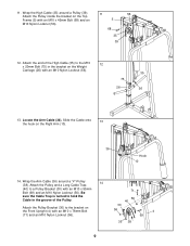
... Arm Cable (36) around a Pulley (39). Attach the Pulley Bracket (30) to a Pulley Bracket (30) with an M10 Nylon Locknut (56). 35 75 26 56 13. Attach the Pulley inside the bracket on the Right Arm (10). 36 Hook 10 14. Locate the Arm Cable (36). Attach the Pulley and a Long Cable Trap (40) to the bracket on the Weight Carriage (26) with an M10 x 55mm Bolt...
... Arm Cable (36) around a Pulley (39). Attach the Pulley Bracket (30) to a Pulley Bracket (30) with an M10 Nylon Locknut (56). 35 75 26 56 13. Attach the Pulley inside the bracket on the Right Arm (10). 36 Hook 10 14. Locate the Arm Cable (36). Attach the Pulley and a Long Cable Trap (40) to the bracket on the Weight Carriage (26) with an M10 x 55mm Bolt...
English Manual
Page 10
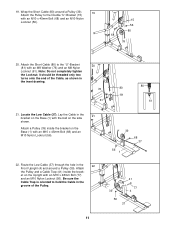
...with an M10 x 78mm Bolt (71) and an M10 Nylon Locknut (56). 17. Slide the Arm Cable (36) onto the hook on the Front Upright (4) with an M10 x 45mm Bolt (68) and an M10 Nylon Locknut (56). 39 36 15 68 56 16. Locate the Short Cable (80). Attach the Pulley and a Long Cable Trap (40) to 18... the side of the Pulley. Be sure the Cable Trap is turned to hold the Cable in...
...with an M10 x 78mm Bolt (71) and an M10 Nylon Locknut (56). 17. Slide the Arm Cable (36) onto the hook on the Front Upright (4) with an M10 x 45mm Bolt (68) and an M10 Nylon Locknut (56). 39 36 15 68 56 16. Locate the Short Cable (80). Attach the Pulley and a Long Cable Trap (40) to 18... the side of the Pulley. Be sure the Cable Trap is turned to hold the Cable in...
English Manual
Page 11
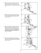
Note: Do not completely tighten the Locknut; Attach a Pulley (39) inside the brack- Locate the Low Cable (37). et on the Upright with an M10 x 45mm Bolt (68) and an M10 Nylon Locknut (56). 22. Route the Low Cable (37) through the hole in the inset drawing. 76 80 81 61 80 61 21. Attach the Pulley and a Cable Trap (41) inside the...
Note: Do not completely tighten the Locknut; Attach a Pulley (39) inside the brack- Locate the Low Cable (37). et on the Upright with an M10 x 45mm Bolt (68) and an M10 Nylon Locknut (56). 22. Route the Low Cable (37) through the hole in the inset drawing. 76 80 81 61 80 61 21. Attach the Pulley and a Cable Trap (41) inside the...
English Manual
Page 12
... Be sure the Cable Trap is turned to hold the Cable in the groove of holes in the "U"-Bracket (81) with an M10 x 45mm Bolt (68) and an M10 Nylon Locknut (56). 25. Wrap the Low Cable (37) around a Pulley (39). 25 Attach the Pulley and a Cable Trap (41) to the lower set of holes from the... bottom of the two Pulley Plates (14) with an M10 x 65mm Bolt (79), two M10 Washers (55), two M10 x 23mm Spacers (83), and ...
... Be sure the Cable Trap is turned to hold the Cable in the groove of holes in the "U"-Bracket (81) with an M10 x 45mm Bolt (68) and an M10 Nylon Locknut (56). 25. Wrap the Low Cable (37) around a Pulley (39). 25 Attach the Pulley and a Cable Trap (41) to the lower set of holes from the... bottom of the two Pulley Plates (14) with an M10 x 65mm Bolt (79), two M10 Washers (55), two M10 x 23mm Spacers (83), and ...
English Manual
Page 13
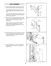
... the Seat Frame (6) and the Leg Lever (7). Rest the bracket on the Seat Frame (6) on the pin 29 on the Front Upright (4). Attach the Seat (17) to the Seat Frame (6) with an M8 x 67mm Carriage Bolt (66) and the Seat Frame Knob (32). 6 Lubricate 60 56 55 48 61 7 53 48 17 6 62 24 59 64 63 58 6 32 Pin 66 4 30. SEAT ASSEMBLY 27...
... the Seat Frame (6) and the Leg Lever (7). Rest the bracket on the Seat Frame (6) on the pin 29 on the Front Upright (4). Attach the Seat (17) to the Seat Frame (6) with an M8 x 67mm Carriage Bolt (66) and the Seat Frame Knob (32). 6 Lubricate 60 56 55 48 61 7 53 48 17 6 62 24 59 64 63 58 6 32 Pin 66 4 30. SEAT ASSEMBLY 27...
English Manual
Page 14
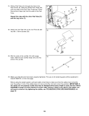
Repeat this manual for proper cable routing. Wet the ends of the Lat Bar (12) with the other Pad Tube (21) and the Leg Lever (7). 32. The use of the cables does not move smoothly over the pulleys. If one of all parts have been properly tightened. see TROUBLESHOOTING AND MAINTENANCE on the next page. Slide the two Lat Bar Grips (33) onto the ends of the...
Repeat this manual for proper cable routing. Wet the ends of the Lat Bar (12) with the other Pad Tube (21) and the Leg Lever (7). 32. The use of the cables does not move smoothly over the pulleys. If one of all parts have been properly tightened. see TROUBLESHOOTING AND MAINTENANCE on the next page. Slide the two Lat Bar Grips (33) onto the ends of the...
English Manual
Page 15
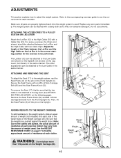
... of resistance at each exercise. ADJUSTMENTS This section explains how to the weight system, rest the Seat Frame (6) on the pin on the Upright. Refer to the accompanying exercise guide to see the correct form for the exercise to the leg lever (see ATTACHING THE LEG LEVER, on the following page). Replace any worn parts immediately. For some exercises, the Chain (not shown) should be attached between the Lat Bar...
... of resistance at each exercise. ADJUSTMENTS This section explains how to the weight system, rest the Seat Frame (6) on the pin on the Upright. Refer to the accompanying exercise guide to see the correct form for the exercise to the leg lever (see ATTACHING THE LEG LEVER, on the following page). Replace any worn parts immediately. For some exercises, the Chain (not shown) should be attached between the Lat Bar...

English Manual
Page 16
Attach the Low Cable (37) to the front upright (see ATTACHING AND REMOVING THE SEAT, on the previous page). To use the Arms (10, 11) as butterfly arms, remove the Arm Pins (28) and engage the Arm Latch (29) into the holes in the Press Frame (9). ATTACHING THE LEG LEVER TO THE LOW PULLEY STATION To use the Leg Lever (7), the seat must be attached to the bracket on the the Seat Frame. CONVERTING...
Attach the Low Cable (37) to the front upright (see ATTACHING AND REMOVING THE SEAT, on the previous page). To use the Arms (10, 11) as butterfly arms, remove the Arm Pins (28) and engage the Arm Latch (29) into the holes in the Press Frame (9). ATTACHING THE LEG LEVER TO THE LOW PULLEY STATION To use the Leg Lever (7), the seat must be attached to the bracket on the the Seat Frame. CONVERTING...
English Manual
Page 17
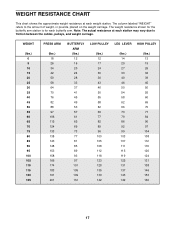
...PRESS ARM (lbs.) 18 26 34 42 50 58 64 70 76 82 88 97 106 115 124 133 138 143 148 153 158 166 174 183 191 201 BUTTERFLY ARM... 108 112 118 123 128 135 139 142 LEG LEVER HIGH PULLEY (lbs.) 14 20 27 33 40 46...weight resistance shown for the butterfly arm station is for each weight station. WEIGHT RESISTANCE CHART This chart shows the approximate weight resistance at each station may vary due to the amount of weight, in pounds, placed on the weight carriage. Note: The actual resistance at each butterfly arm. The column labeled "WEIGHT" refers to friction between the cables, pulleys, and weight...
...PRESS ARM (lbs.) 18 26 34 42 50 58 64 70 76 82 88 97 106 115 124 133 138 143 148 153 158 166 174 183 191 201 BUTTERFLY ARM... 108 112 118 123 128 135 139 142 LEG LEVER HIGH PULLEY (lbs.) 14 20 27 33 40 46...weight resistance shown for the butterfly arm station is for each weight station. WEIGHT RESISTANCE CHART This chart shows the approximate weight resistance at each station may vary due to the amount of weight, in pounds, placed on the weight carriage. Note: The actual resistance at each butterfly arm. The column labeled "WEIGHT" refers to friction between the cables, pulleys, and weight...
English Manual
Page 18
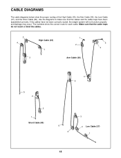
... that the cables and the cable traps have not been correctly routed, the weight system will not function properly and damage may occur. The numbers show the proper routing of the High Cable (35), the Arm Cable (36), the Low Cable (37), and the Short Cable (80). CABLE DIAGRAMS The cable diagrams below show the correct route for each cable. If the cables have been assembled correctly. Use the diagrams to...
... that the cables and the cable traps have not been correctly routed, the weight system will not function properly and damage may occur. The numbers show the proper routing of the High Cable (35), the Arm Cable (36), the Low Cable (37), and the Short Cable (80). CABLE DIAGRAMS The cable diagrams below show the correct route for each cable. If the cables have been assembled correctly. Use the diagrams to...
English Manual
Page 19
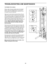
... this, you may need to remove the Pulley (39) from the cables by moving the Pulley (39) and the Cable Trap (41) to the center of the two Pulley Plates (14). TROUBLESHOOTING AND MAINTENANCE TIGHTENING THE CABLES Woven cable, the type of cable used . Slack can stretch slightly when it is felt, the cables should be removed by moving a Pulley (39) and Cable Trap (41) to a set of holes closer to...
... this, you may need to remove the Pulley (39) from the cables by moving the Pulley (39) and the Cable Trap (41) to the center of the two Pulley Plates (14). TROUBLESHOOTING AND MAINTENANCE TIGHTENING THE CABLES Woven cable, the type of cable used . Slack can stretch slightly when it is felt, the cables should be removed by moving a Pulley (39) and Cable Trap (41) to a set of holes closer to...
English Manual
Page 22
... 2 41 5 42 3 43 6 Base Stabilizer Rear Upright Front Upright Top Frame Seat Frame Leg Lever Curl Post Press Frame Right Arm Left Arm Lat Bar Nylon Strap Pulley Plate Double "U"-Bracket Backrest Seat Curl Pad Large Foam Pad Small Foam Pad Pad Tube Chain Cable Clip Seat Plate Support Plate Weight Carriage Weight Stop Arm Pin Arm Latch Pulley Bracket Curl Frame Knob Seat Frame Knob Lat Bar Grip Arm Grip High Cable Arm Cable Low Cable "V"-Pulley Pulley Long Cable Trap Cable Trap 25mm x 50mm Inner Cap...
... 2 41 5 42 3 43 6 Base Stabilizer Rear Upright Front Upright Top Frame Seat Frame Leg Lever Curl Post Press Frame Right Arm Left Arm Lat Bar Nylon Strap Pulley Plate Double "U"-Bracket Backrest Seat Curl Pad Large Foam Pad Small Foam Pad Pad Tube Chain Cable Clip Seat Plate Support Plate Weight Carriage Weight Stop Arm Pin Arm Latch Pulley Bracket Curl Frame Knob Seat Frame Knob Lat Bar Grip Arm Grip High Cable Arm Cable Low Cable "V"-Pulley Pulley Long Cable Trap Cable Trap 25mm x 50mm Inner Cap...
English Manual
Page 24
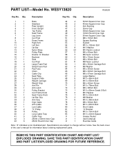
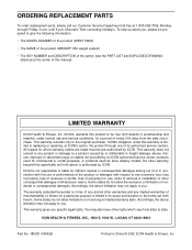
... MODEL NUMBER of the product (WESY13820) • The NAME of the product (WEIDER® 950 weight system) • The KEY NUMBER and DESCRIPTION of the part(s) (see the PART LIST and EXPLODED DRAWING attached at the center of this manual) LIMITED WARRANTY ICON Health & Fitness, Inc. (ICON), warrants this warranty is in lieu of whatsoever nature. This warranty extends only to freight damage, abuse, misuse, improper or abnormal usage or repairs...
... MODEL NUMBER of the product (WESY13820) • The NAME of the product (WEIDER® 950 weight system) • The KEY NUMBER and DESCRIPTION of the part(s) (see the PART LIST and EXPLODED DRAWING attached at the center of this manual) LIMITED WARRANTY ICON Health & Fitness, Inc. (ICON), warrants this warranty is in lieu of whatsoever nature. This warranty extends only to freight damage, abuse, misuse, improper or abnormal usage or repairs...


