
Uk Manual
Page 1
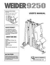
....com Model No.WEEVSY59220 Serial No. (Write the serial number in this manual before using this manual for reference.) Serial Number Decal (under seat) QUESTIONS? As a manufacturer, we are missing or damaged parts, please call: 08457 089 009 Or write: ICON Health & Fitness, Ltd. Unit 4 Revie Road Industrial Estate Revie Road Beeston Leeds, LS118JG UK email: [email protected] CAUTION Read all precautions and instructions...
....com Model No.WEEVSY59220 Serial No. (Write the serial number in this manual before using this manual for reference.) Serial Number Decal (under seat) QUESTIONS? As a manufacturer, we are missing or damaged parts, please call: 08457 089 009 Or write: ICON Health & Fitness, Ltd. Unit 4 Revie Road Industrial Estate Revie Road Beeston Leeds, LS118JG UK email: [email protected] CAUTION Read all precautions and instructions...
Uk Manual
Page 2
TABLE OF CONTENTS IMPORTANT PRECAUTIONS 3 BEFORE YOU BEGIN 4 ASSEMBLY 5 ADJUSTMENTS 21 TROUBLESHOOTING AND MAINTENANCE 24 CABLE DIAGRAMS 25 EXERCISE GUIDELINES 26 ORDERING REPLACEMENT PARTS Back Cover Note: A PART IDENTIFICATION CHART and a PART LIST/EXPLODED DRAWING are attached in the centre of ICON Health & Fitness, Inc. 2 Remove the PART IDENTIFICATION CHART and PART LIST/EXPLODED DRAWING before beginning assembly. WEIDER is a registered trademark of this manual.
TABLE OF CONTENTS IMPORTANT PRECAUTIONS 3 BEFORE YOU BEGIN 4 ASSEMBLY 5 ADJUSTMENTS 21 TROUBLESHOOTING AND MAINTENANCE 24 CABLE DIAGRAMS 25 EXERCISE GUIDELINES 26 ORDERING REPLACEMENT PARTS Back Cover Note: A PART IDENTIFICATION CHART and a PART LIST/EXPLODED DRAWING are attached in the centre of ICON Health & Fitness, Inc. 2 Remove the PART IDENTIFICATION CHART and PART LIST/EXPLODED DRAWING before beginning assembly. WEIDER is a registered trademark of this manual.

Uk Manual
Page 3
... exercising, stop immediately and make sure that the cables remain on page 4. Never release the press arm, butterfly arms, leg lever, lat bar, curl bar, handle, ab strap, or ankle strap whilst weights are properly tightened each time the weight system is missing or illegible, call our Customer Service Department toll-free at any worn parts immediately. 6. Always stand on all precautions. 3. It is especially important for home use the weight...
... exercising, stop immediately and make sure that the cables remain on page 4. Never release the press arm, butterfly arms, leg lever, lat bar, curl bar, handle, ab strap, or ankle strap whilst weights are properly tightened each time the weight system is missing or illegible, call our Customer Service Department toll-free at any worn parts immediately. 6. Always stand on all precautions. 3. It is especially important for home use the weight...
Uk Manual
Page 4
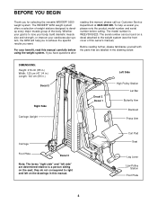
... with the parts that are determined relative to the weight system (see the front cover of this manual, please call our Customer Service Department at 0845 089 009. Curl Pad Seat Leg Lever Low Pulley Station Foot Plate 4 To help you to achieve the specific results you have questions after reading this owner's manual). The serial number can be found on a decal attached to...
... with the parts that are determined relative to the weight system (see the front cover of this manual, please call our Customer Service Department at 0845 089 009. Curl Pad Seat Leg Lever Low Pulley Station Foot Plate 4 To help you to achieve the specific results you have questions after reading this owner's manual). The serial number can be found on a decal attached to...
Uk Manual
Page 5
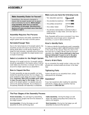
..., assemble the weight system with the help you have been pre-attached. Select a Location for each assembly step. By setting aside plenty of time and by assembling the base and the uprights that connect the arms to do otherwise. How to read the information on the floor and use it . Note: Assembly will be more time than it takes to Unpack the Box Tightening Parts To...
..., assemble the weight system with the help you have been pre-attached. Select a Location for each assembly step. By setting aside plenty of time and by assembling the base and the uprights that connect the arms to do otherwise. How to read the information on the floor and use it . Note: Assembly will be more time than it takes to Unpack the Box Tightening Parts To...
Uk Manual
Page 9
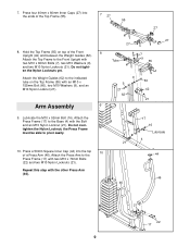
7. Arm Assembly 9 Tube 7 9 55 9 60 9 21 42 62 21 9. Do not overtighten the Nylon Locknut; en the Nylon Locknuts yet. Attach the Weight Guides (62) to the Base (4) with the Bolt and an M10 Nylon Locknut (21). Attach the Press Frame (17) to the indicated tube on top of the Front 8 Upright (42) and between the Weight Guides (62). the Press Frame must...
7. Arm Assembly 9 Tube 7 9 55 9 60 9 21 42 62 21 9. Do not overtighten the Nylon Locknut; en the Nylon Locknuts yet. Attach the Weight Guides (62) to the Base (4) with the Bolt and an M10 Nylon Locknut (21). Attach the Press Frame (17) to the indicated tube on top of the Front 8 Upright (42) and between the Weight Guides (62). the Press Frame must...
Uk Manual
Page 13
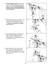
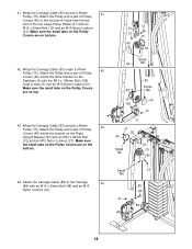
... tighten the Nylon Locknut; Make sure the small tabs on the Pulley Covers are on each end. Wrap the Weight Cable (23) around a 90mm Pulley (15). Wrap the Weight Cable (23) under a 90mm Pulley 23 (15). Attach the Cable to the Pulley Plates (58) with an M8 Washer (70) and an M8 Nylon Locknut (3). Bracket (90) with an M10 x 52mm Bolt ...21). 3 70 90 23 90 3 11 23 21 Small Tabs 58 40 15 40 58 12 55 15 77 23 77 76 9 21 9 25. Route the Weight Cable (23) up through the Top Frame (55). Locate the Weight Cable (23), which has a bolt 22 on top. 24.
... tighten the Nylon Locknut; Make sure the small tabs on the Pulley Covers are on each end. Wrap the Weight Cable (23) around a 90mm Pulley (15). Wrap the Weight Cable (23) under a 90mm Pulley 23 (15). Attach the Cable to the Pulley Plates (58) with an M8 Washer (70) and an M8 Nylon Locknut (3). Bracket (90) with an M10 x 52mm Bolt ...21). 3 70 90 23 90 3 11 23 21 Small Tabs 58 40 15 40 58 12 55 15 77 23 77 76 9 21 9 25. Route the Weight Cable (23) up through the Top Frame (55). Locate the Weight Cable (23), which has a bolt 22 on top. 24.
Uk Manual
Page 14
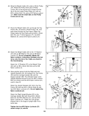
...Weight Cable (23) under a 90mm Pulley 26 (15). it should fit over the M10 x 80mm Bolt (not shown) and the M10 Nylon Locknut (21) used in the inset drawing. Attach the Left Upright Bracket (94) to the second set of holes from the top of the Cable, as shown in step 3, 8, and 29. 14 Attach the Upright...small tabs on the Pulley Covers are on top. 27. Do not completely tighten the Nylon Locknut; 26. Attach the Pulley inside the Top Frame with an M10 x 52mm Bolt (12) and an M10 Nylon Locknut (21). Attach the Pulley and a pair of Pulley Covers (40) to the Support Upright (88) in ...
...Weight Cable (23) under a 90mm Pulley 26 (15). it should fit over the M10 x 80mm Bolt (not shown) and the M10 Nylon Locknut (21) used in the inset drawing. Attach the Left Upright Bracket (94) to the second set of holes from the top of the Cable, as shown in step 3, 8, and 29. 14 Attach the Upright...small tabs on the Pulley Covers are on top. 27. Do not completely tighten the Nylon Locknut; 26. Attach the Pulley inside the Top Frame with an M10 x 52mm Bolt (12) and an M10 Nylon Locknut (21). Attach the Pulley and a pair of Pulley Covers (40) to the Support Upright (88) in ...
Uk Manual
Page 15
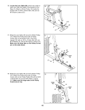
... 40 58 12 Large Tab 15 40 69 15 Rest the Cable in the Front Upright (42) with an M10 x 52mm Bolt (12) and an M10 Nylon Locknut (21). Attach the Pulley and a pair of Pulley Covers (40) to the Pulley Plates (58) with an M10 x 110mm Bolt (64), an M10 Washer (9), and an M10 Nylon Locknut... on the Base (4). Make sure the large tabs on the Pulley Covers are on 30 each end. Attach a 90mm Pulley (15) inside the bracket with an M10 x 45mm Bolt (100) and an M10 Nylon Locknut (21). 15 4 21 100 69 31. Locate the Low Cable (69), which has a ball on the side shown. 42 ...
... 40 58 12 Large Tab 15 40 69 15 Rest the Cable in the Front Upright (42) with an M10 x 52mm Bolt (12) and an M10 Nylon Locknut (21). Attach the Pulley and a pair of Pulley Covers (40) to the Pulley Plates (58) with an M10 x 110mm Bolt (64), an M10 Washer (9), and an M10 Nylon Locknut... on the Base (4). Make sure the large tabs on the Pulley Covers are on 30 each end. Attach a 90mm Pulley (15) inside the bracket with an M10 x 45mm Bolt (100) and an M10 Nylon Locknut (21). 15 4 21 100 69 31. Locate the Low Cable (69), which has a ball on the side shown. 42 ...
Uk Manual
Page 16
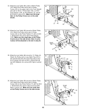
... sure the small tabs on the Pulley Covers are on the Front Upright (42) with an M10 x 115mm Bolt (102), an M10 Thick Spacer (104), an M10 Washer (9), and an M10 Nylon Locknut (21). Attach the Pulley and a pair of Pulley Covers (40) to the Press Frame (17) with the M10 x 135mm Bolt (75) used in step 36. 69 17 Small Tab...
... sure the small tabs on the Pulley Covers are on the Front Upright (42) with an M10 x 115mm Bolt (102), an M10 Thick Spacer (104), an M10 Washer (9), and an M10 Nylon Locknut (21). Attach the Pulley and a pair of Pulley Covers (40) to the Press Frame (17) with the M10 x 135mm Bolt (75) used in step 36. 69 17 Small Tab...
Uk Manual
Page 18
... bot- Make sure the small tabs on the Pulley Covers are on the Right Upright Bracket (93) with the M10 x 105mm Bolt (106) used in step 40, and an M10 Nylon Locknut (21). Make sure the small tabs on the Pulley Covers are on bottom. 42. Attach the Pulley and a pair of Pulley Covers (40) inside the bracket on the bottom. 12...
... bot- Make sure the small tabs on the Pulley Covers are on the Right Upright Bracket (93) with the M10 x 105mm Bolt (106) used in step 40, and an M10 Nylon Locknut (21). Make sure the small tabs on the Pulley Covers are on bottom. 42. Attach the Pulley and a pair of Pulley Covers (40) inside the bracket on the bottom. 12...
Uk Manual
Page 20
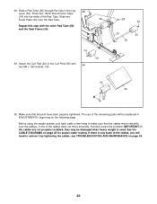
... properly tightened. 48. Attach the Curl Pad (24) to remove it by tightening the cables; Make sure that the cables move smoothly, find and correct the problem. If there is used. Slide a Pad Tube (28) through the hole in the cables, you will be damaged when heavy weight is any slack in the Leg 48 Lever (29). The use of the remaining parts will need...
... properly tightened. 48. Attach the Curl Pad (24) to remove it by tightening the cables; Make sure that the cables move smoothly, find and correct the problem. If there is used. Slide a Pad Tube (28) through the hole in the cables, you will be damaged when heavy weight is any slack in the Leg 48 Lever (29). The use of the remaining parts will need...
Uk Manual
Page 21
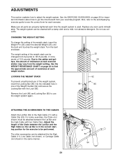
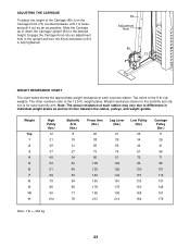
... accompanying exercise guide to adjust the weight system. CHANGING THE WEIGHT SETTING To change the setting of 12.5 pounds. Use the WEIGHT RESISTANCE CHART on page 26 for important information about how to use of the weight system, insert the Locking Bar (85) into the indicated hole in increments of the weight stack, insert the Weight Pin (26) under the desired Weight (25) until the bent end touches the weight stack. Remove the...
... accompanying exercise guide to adjust the weight system. CHANGING THE WEIGHT SETTING To change the setting of 12.5 pounds. Use the WEIGHT RESISTANCE CHART on page 26 for important information about how to use of the weight system, insert the Locking Bar (85) into the indicated hole in increments of the weight stack, insert the Weight Pin (26) under the desired Weight (25) until the bent end touches the weight stack. Remove the...
Uk Manual
Page 22
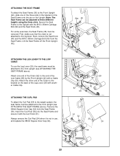
... Seat Knob (49). For some exercises, the Seat Frame (36) must be adjusted to the leg lever. ATTACHING THE CURL PAD To attach the Curl Pad (24) to the weight system, the seat frame must be attached to the front upright (see ATTACHING THE SEAT FRAME above ). Insert the Curl Post (35) into the Seat Frame and secure it is not attached to three different heights using...
... Seat Knob (49). For some exercises, the Seat Frame (36) must be adjusted to the leg lever. ATTACHING THE CURL PAD To attach the Curl Pad (24) to the weight system, the seat frame must be attached to the front upright (see ATTACHING THE SEAT FRAME above ). Insert the Curl Post (35) into the Seat Frame and secure it is not attached to three different heights using...
Uk Manual
Page 23
...Upright (84) to the 6 lb. Note: The actual resistance at each exercise station. Weight Top 1 2 3 4 5 6 7 8 9 10 11 High Pulley (lbs.) 12 21 29 37 45 53 61 69 79 86 96 104 Butterfly Arm (lbs.) 8 15 21 27 34 40 46 53 59 65 71 78 Press Arm (lbs.) Leg Lever (lbs.) Low Pulley... 176 Note: 1 lb = .454 kg 23 The other numbers refer to differences in the upright and turn the Carriage Knob (73) counterclockwise until it out as far as friction between the cables, pulleys, and weight guides. Weight resistance shown for the butterfly arm station is for each station may vary due to the 12...
...Upright (84) to the 6 lb. Note: The actual resistance at each exercise station. Weight Top 1 2 3 4 5 6 7 8 9 10 11 High Pulley (lbs.) 12 21 29 37 45 53 61 69 79 86 96 104 Butterfly Arm (lbs.) 8 15 21 27 34 40 46 53 59 65 71 78 Press Arm (lbs.) Leg Lever (lbs.) Low Pulley... 176 Note: 1 lb = .454 kg 23 The other numbers refer to differences in the upright and turn the Carriage Knob (73) counterclockwise until it out as far as friction between the cables, pulleys, and weight guides. Weight resistance shown for the butterfly arm station is for each station may vary due to the 12...
Uk Manual
Page 24
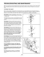
... closer to a higher set of the Weight Cable (23) to the Large "U"-Bracket (90). Tighten the M8 Nylon Locknut (3) that the cable and pulley move smoothly. Make sure that 1 connects the end of holes in the Large Pulley Plates with the Bolt, Washers, and Nylon Locknut. Do not overtighten the cables. Do not use solvents. TROUBLESHOOTING AND MAINTENANCE Make sure all parts are overtightened, the...
... closer to a higher set of the Weight Cable (23) to the Large "U"-Bracket (90). Tighten the M8 Nylon Locknut (3) that the cable and pulley move smoothly. Make sure that 1 connects the end of holes in the Large Pulley Plates with the Bolt, Washers, and Nylon Locknut. Do not overtighten the cables. Do not use solvents. TROUBLESHOOTING AND MAINTENANCE Make sure all parts are overtightened, the...
Uk Manual
Page 26
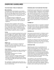
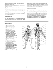
... at any exercise program. formed. (A "repetition" is the highest. This requires moving only the appropriate parts of 15 to 10 minutes of your energy level is one sit-up. Complete as many sets of the body. You should be followed by using high amounts of an exercise, such as you perform. On the exercise guide accompanying this manual you will continually adapt and...
... at any exercise program. formed. (A "repetition" is the highest. This requires moving only the appropriate parts of 15 to 10 minutes of your energy level is one sit-up. Complete as many sets of the body. You should be followed by using high amounts of an exercise, such as you perform. On the exercise guide accompanying this manual you will continually adapt and...
Uk Manual
Page 27
... set for a toning work- List the date, the exercises performed, the weight used, and the numbers of calf) K. Hip Flexors (upper thigh) G. Tibialis Anterior (front of sets and repetitions completed. Soleus (front of arm) B D. Spinae Erectors (lower back) K T. Record your arms and legs....exercise a regular and enjoyable part of your everyday life. Plan to increase flexibility. Ease into each workout with the equipment and learning the proper form for each set for a weight loss workout. Rest for a short period of time after each exercise. Remember, the key...
... set for a toning work- List the date, the exercises performed, the weight used, and the numbers of calf) K. Hip Flexors (upper thigh) G. Tibialis Anterior (front of sets and repetitions completed. Soleus (front of arm) B D. Spinae Erectors (lower back) K T. Record your arms and legs....exercise a regular and enjoyable part of your everyday life. Plan to increase flexibility. Ease into each workout with the equipment and learning the proper form for each set for a weight loss workout. Rest for a short period of time after each exercise. Remember, the key...
Uk Manual
Page 28
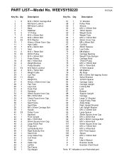
... information when ordering replacement parts: • the MODEL NUMBER of the product (WEEVSY59220) • the NAME of the product (WEIDER® 9250 weight system) • the SERIAL NUMBER of the product (see the front cover of this manual) • the KEY NUMBER and DESCRIPTION of the part(s) (see the PART LIST and EXPLODED DRAWING in the centre of this manual) Part No. 186999 R0702A Printed in China © 2002 ICON Health & Fitness...
... information when ordering replacement parts: • the MODEL NUMBER of the product (WEEVSY59220) • the NAME of the product (WEIDER® 9250 weight system) • the SERIAL NUMBER of the product (see the front cover of this manual) • the KEY NUMBER and DESCRIPTION of the part(s) (see the PART LIST and EXPLODED DRAWING in the centre of this manual) Part No. 186999 R0702A Printed in China © 2002 ICON Health & Fitness...
Uk Manual
Page 34
...-tapping Screw Swivel Bracket 12.5mm Spacer Carriage Cable Carriage Upright Locking Bar Lock Bumper Support Upright Carriage Large "U"-Bracket Large Pulley Plate Ankle Strap Right Upright Bracket Left Upright Bracket M10 x 120mm Bolt Large Spacer 25mm Square Inner Cap M10 x 20mm Bolt M10 x 80mm Carriage Bolt M10 x 45mm Bolt 60mm Square Inner Cap M10 x 115mm Bolt M10 x 47mm Bolt M10 Thick Spacer Sleeve M10 x 105mm Bolt Key User's Manual Exercise Guide Exercise Chart...
...-tapping Screw Swivel Bracket 12.5mm Spacer Carriage Cable Carriage Upright Locking Bar Lock Bumper Support Upright Carriage Large "U"-Bracket Large Pulley Plate Ankle Strap Right Upright Bracket Left Upright Bracket M10 x 120mm Bolt Large Spacer 25mm Square Inner Cap M10 x 20mm Bolt M10 x 80mm Carriage Bolt M10 x 45mm Bolt 60mm Square Inner Cap M10 x 115mm Bolt M10 x 47mm Bolt M10 Thick Spacer Sleeve M10 x 105mm Bolt Key User's Manual Exercise Guide Exercise Chart...


