

English Manual
Page 8
... (42) with the ball is in place. 8 7 50 6 42 58 21 7 50 6 47 21 58 Before beginning this manual to verify proper cable routing. Route the Long Cable (58) around a "V"-Pulley (6). Be sure that the end of the Cable with an M10 x 60mm Bolt (7) and an M10 Nylon Locknut (21). Attach the Pulley and a Long...
... (42) with the ball is in place. 8 7 50 6 42 58 21 7 50 6 47 21 58 Before beginning this manual to verify proper cable routing. Route the Long Cable (58) around a "V"-Pulley (6). Be sure that the end of the Cable with an M10 x 60mm Bolt (7) and an M10 Nylon Locknut (21). Attach the Pulley and a Long...

English Manual
Page 9
... x 45mm Bolt (12) and an M10 Nylon Locknut (21). Route the Long Cable (58) around the 90mm Pulley (15) attached to the Long "U"-Bracket with a 90mm Pulley (15) and a Cable Trap (66). Route the Long Cable (58) between the 90mm Pulley (15) and 14 the Cable Trap (not shown) attached to the Pulley Bracket (20). Note...
... x 45mm Bolt (12) and an M10 Nylon Locknut (21). Route the Long Cable (58) around the 90mm Pulley (15) attached to the Long "U"-Bracket with a 90mm Pulley (15) and a Cable Trap (66). Route the Long Cable (58) between the 90mm Pulley (15) and 14 the Cable Trap (not shown) attached to the Pulley Bracket (20). Note...

English Manual
Page 10
...Press Frame (17). 23 Crossbar 17 15 Ball 10 Locate the Short Cable (23). Attach the Long Cable (58) to the Weight Carriage (19) with an M10 x ...198mm Bolt (59), two M10 Washers (9), and an M10 Nylon Locknut (21). 21 9 15 66 9 25 59 Bracket 15 17 18. Make sure that the Cable... is between the Pulley and the crossbar on the Press Frame (17). Be sure that the Cable Trap and ...and an M10 Nylon Locknut (21). Attach a 90mm Pulley (15) and a Cable Trap (66) 17 to the Press Frame with an M10 x 20mm Bolt (...
...Press Frame (17). 23 Crossbar 17 15 Ball 10 Locate the Short Cable (23). Attach the Long Cable (58) to the Weight Carriage (19) with an M10 x ...198mm Bolt (59), two M10 Washers (9), and an M10 Nylon Locknut (21). 21 9 15 66 9 25 59 Bracket 15 17 18. Make sure that the Cable... is between the Pulley and the crossbar on the Press Frame (17). Be sure that the Cable Trap and ...and an M10 Nylon Locknut (21). Attach a 90mm Pulley (15) and a Cable Trap (66) 17 to the Press Frame with an M10 x 20mm Bolt (...

English Manual
Page 11
... view from other side 23 15 15 66 21 21 17 11 Refer to the upper hole in place. Route the Short Cable (23) around the 90mm Pulley (15) attached to hold the Cable in the 21 Press Frame (17). Insert the Bolts into the Front Upright (42) from other side 21. Hand... turned to the upper hole in place. Properly tighten the M10 Nylon Locknut (21) Route the Short Cable (23) around the 90mm 20 Pulley (15) attached to hold the Cable in the Front Upright (42). Be sure that the Cable Trap (66) is turned to the lower hole in place. Do not tighten the...
... view from other side 23 15 15 66 21 21 17 11 Refer to the upper hole in place. Route the Short Cable (23) around the 90mm Pulley (15) attached to hold the Cable in the 21 Press Frame (17). Insert the Bolts into the Front Upright (42) from other side 21. Hand... turned to the upper hole in place. Properly tighten the M10 Nylon Locknut (21) Route the Short Cable (23) around the 90mm 20 Pulley (15) attached to hold the Cable in the Front Upright (42). Be sure that the Cable Trap (66) is turned to the lower hole in place. Do not tighten the...
English Manual
Page 14
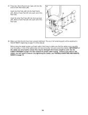
... Make sure that the cables move smoothly, find and correct the problem. see TROUBLE-SHOOTING AND MAINTENANCE on page 15 of all parts have been properly tightened. The use of this manual for proper cable routing. See the CABLE DIAGRAM on page 19 of the cables does not move smoothly over... the pulleys. Slide a Foam Pad (30) onto each cable a few times to make sure that all remaining parts will need to...
... Make sure that the cables move smoothly, find and correct the problem. see TROUBLE-SHOOTING AND MAINTENANCE on page 15 of all parts have been properly tightened. The use of this manual for proper cable routing. See the CABLE DIAGRAM on page 19 of the cables does not move smoothly over... the pulleys. Slide a Foam Pad (30) onto each cable a few times to make sure that all remaining parts will need to...

English Manual
Page 19
... numbers show the correct position of each cable trap. The starting and ending points of the Short Cable (23) and the Long Cable (58). The small drawings show the correct route for each cable are labeled. Make sure that the two cables and the cable traps have not been correctly routed, the weight system will not function properly...
... numbers show the correct position of each cable trap. The starting and ending points of the Short Cable (23) and the Long Cable (58). The small drawings show the correct route for each cable are labeled. Make sure that the two cables and the cable traps have not been correctly routed, the weight system will not function properly...

