

English Manual
Page 2
TABLE OF CONTENTS IMPORTANT PRECAUTIONS 3 BEFORE YOU BEGIN 4 ASSEMBLY 5 ADJUSTMENT 15 WEIGHT RESISTANCE CHART 17 TROUBLE-SHOOTING AND MAINTENANCE 18 CABLE DIAGRAM 19 EXERCISE GUIDELINES 20 PART LIST 22 EXPLODED DRAWING 23 ORDERING REPLACEMENT PARTS Back Cover FULL 90 DAY WARRANTY Back Cover Note: A PART IDENTIFICATION CHART is attached in the center of this manual. Remove the PART IDENTIFICATION CHART before beginning assembly. 2
TABLE OF CONTENTS IMPORTANT PRECAUTIONS 3 BEFORE YOU BEGIN 4 ASSEMBLY 5 ADJUSTMENT 15 WEIGHT RESISTANCE CHART 17 TROUBLE-SHOOTING AND MAINTENANCE 18 CABLE DIAGRAM 19 EXERCISE GUIDELINES 20 PART LIST 22 EXPLODED DRAWING 23 ORDERING REPLACEMENT PARTS Back Cover FULL 90 DAY WARRANTY Back Cover Note: A PART IDENTIFICATION CHART is attached in the center of this manual. Remove the PART IDENTIFICATION CHART before beginning assembly. 2

English Manual
Page 8
...) with an M10 x 60mm Bolt (7) and an M10 Nylon Locknut (21). Before beginning this section, identify the Short Cable (23) and the Long Cable (58) by comparing the ends of the Pulley and that the Cable is positioned to the CABLE DIAGRAM on the Front Upright (42) with the ball is positioned to hold the...
...) with an M10 x 60mm Bolt (7) and an M10 Nylon Locknut (21). Before beginning this section, identify the Short Cable (23) and the Long Cable (58) by comparing the ends of the Pulley and that the Cable is positioned to the CABLE DIAGRAM on the Front Upright (42) with the ball is positioned to hold the...
English Manual
Page 14
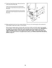
... slack in ADJUSTMENT, beginning on page 15 of this manual. Before using the weight system, pull each cable a few times to remove it by tightening the cables; If one Pad Tube (28) into the Seat Frame (36). See the CABLE DIAGRAM on page 18. 14 Slide a Foam Pad (30) onto each end of the... cables does not move smoothly over the pulleys. see TROUBLE-SHOOTING AND MAINTENANCE on page 19 of this manual for proper cable routing. 27. Insert one of the Pad Tube. 36...
... slack in ADJUSTMENT, beginning on page 15 of this manual. Before using the weight system, pull each cable a few times to remove it by tightening the cables; If one Pad Tube (28) into the Seat Frame (36). See the CABLE DIAGRAM on page 18. 14 Slide a Foam Pad (30) onto each end of the... cables does not move smoothly over the pulleys. see TROUBLE-SHOOTING AND MAINTENANCE on page 19 of this manual for proper cable routing. 27. Insert one of the Pad Tube. 36...

English Manual
Page 19
... and ending points of the Short Cable (23) and the Long Cable (58). CABLE DIAGRAM The cable diagram below shows the proper routing of each cable are labeled. If the cables have been assembled correctly. Use the diagram to be sure that the cable traps do not touch or bind the cables. 2 1-High Pulley 7 3 5 4 Long Cable (58) TOP VIEW 6 5-Long "U"-Bracket Short...
... and ending points of the Short Cable (23) and the Long Cable (58). CABLE DIAGRAM The cable diagram below shows the proper routing of each cable are labeled. If the cables have been assembled correctly. Use the diagram to be sure that the cable traps do not touch or bind the cables. 2 1-High Pulley 7 3 5 4 Long Cable (58) TOP VIEW 6 5-Long "U"-Bracket Short...


