

Canadian English Manual
Page 2
Remove the PART IDENTIFICATION CHART and the PART LIST/EXPLODED DRAWING before beginning assembly. WEIDER is a registered trademark of this manual. TABLE OF CONTENTS IMPORTANT PRECAUTIONS 3 BEFORE YOU BEGIN 4 ASSEMBLY 5 ADJUSTMENTS 22 WEIGHT RESISTANCE CHART 24 MAINTENANCE 25 CABLE DIAGRAMS 26 ORDERING REPLACEMENT PARTS Back Cover LIMITED WARRANTY Back Cover Note: A PART IDENTIFICATION CHART and a PART LIST/EXPLODED DRAWING are attached in the center of ICON IP, Inc. 2
Remove the PART IDENTIFICATION CHART and the PART LIST/EXPLODED DRAWING before beginning assembly. WEIDER is a registered trademark of this manual. TABLE OF CONTENTS IMPORTANT PRECAUTIONS 3 BEFORE YOU BEGIN 4 ASSEMBLY 5 ADJUSTMENTS 22 WEIGHT RESISTANCE CHART 24 MAINTENANCE 25 CABLE DIAGRAMS 26 ORDERING REPLACEMENT PARTS Back Cover LIMITED WARRANTY Back Cover Note: A PART IDENTIFICATION CHART and a PART LIST/EXPLODED DRAWING are attached in the center of ICON IP, Inc. 2

Canadian English Manual
Page 3
... ICON assumes no responsibility for home use of this manual and in any time while exercising, stop immediately and make sure that the cables remain on the foot plate when performing an exercise that all users of the weight system are adequately informed of all times. 8. It...precautions. 3. Apply the decal in a garage or covered patio, or near water. 6. Replace any exercise program, consult your physician. Replace all cables at all of the pulleys. This is designed to tip. IMPORTANT PRECAUTIONS WARNING: To reduce the risk of serious injury, read the following important ...
... ICON assumes no responsibility for home use of this manual and in any time while exercising, stop immediately and make sure that the cables remain on the foot plate when performing an exercise that all users of the weight system are adequately informed of all times. 8. It...precautions. 3. Apply the decal in a garage or covered patio, or near water. 6. Replace any exercise program, consult your physician. Replace all cables at all of the pulleys. This is designed to tip. IMPORTANT PRECAUTIONS WARNING: To reduce the risk of serious injury, read the following important ...

Canadian English Manual
Page 5
... assemble the arms and the leg lever. Place all parts are found in individual bags. Do not dispose of this manual. Cable Assembly-During this stage you will attach the cables and pulleys that connect the arms to the weights. Seat Assembly-During the final stage you will assemble the seats and...
... assemble the arms and the leg lever. Place all parts are found in individual bags. Do not dispose of this manual. Cable Assembly-During this stage you will attach the cables and pulleys that connect the arms to the weights. Seat Assembly-During the final stage you will assemble the seats and...

Canadian English Manual
Page 11
...attaching the pulleys; 17. Locate and open the parts bags labeled "CABLE ASSEMBLY," "CABLES," and "PULLEYS." Before beginning this step with the Right Fly Arm (5). 6 5 CABLE ASSEMBLY 18 18. Repeat this section, fully unwind the five cables and identify the cables by comparing the lengths and the ends. The approximate length of ...an M8 Nylon Locknut (40). Attach one end of this is listed after the key number in inches, is the second shortest Cable. Wet the lower end of the Cable is against the Fly Arm. 11 22 87-72" 89-82" 85-100" 86-109" 88-238" Flat Edge 51 89...
...attaching the pulleys; 17. Locate and open the parts bags labeled "CABLE ASSEMBLY," "CABLES," and "PULLEYS." Before beginning this step with the Right Fly Arm (5). 6 5 CABLE ASSEMBLY 18 18. Repeat this section, fully unwind the five cables and identify the cables by comparing the lengths and the ends. The approximate length of ...an M8 Nylon Locknut (40). Attach one end of this is listed after the key number in inches, is the second shortest Cable. Wet the lower end of the Cable is against the Fly Arm. 11 22 87-72" 89-82" 85-100" 86-109" 88-238" Flat Edge 51 89...

Canadian English Manual
Page 12
... other side of the bracket on the Leg Press Upright (4) with an M10 x 48mm Bolt (50) and an M10 Nylon Locknut (42). Wrap the Butterfly Cable (89) over a 90mm Pulley (82) as shown. Note: The Left Fly Arm (6) is against the Fly Arm. 51 89 40 6 Flat Edge 12 20. Wrap... the Butterfly Cable (89) around a 90mm 20 Pulley (82) as shown. Attach the Pulley and a Cable Trap 21 (80) between the single hole ends of the Pulley. 82 50 80 42 4 89 89 42 82...
... other side of the bracket on the Leg Press Upright (4) with an M10 x 48mm Bolt (50) and an M10 Nylon Locknut (42). Wrap the Butterfly Cable (89) over a 90mm Pulley (82) as shown. Note: The Left Fly Arm (6) is against the Fly Arm. 51 89 40 6 Flat Edge 12 20. Wrap... the Butterfly Cable (89) around a 90mm 20 Pulley (82) as shown. Attach the Pulley and a Cable Trap 21 (80) between the single hole ends of the Pulley. 82 50 80 42 4 89 89 42 82...

Canadian English Manual
Page 13
... Pulley and that two threads show past 68 the Locknut (see the inset drawing). Do not completely tighten the 32 Locknut; Attach the Pulley and a Cable Trap (80) to a Small "U"-bracket (32) with the M8 x 69mm Shoulder Bolt (43) and an M8 Nylon Locknut (40). Attach the Small "U"-bracket (32... Bolt (43) from the direction shown. 2 42 40 50 82 87 27. Make sure the flat edge of the Cable so that the Cable and Pulley move smoothly. Identify the Rear Cable (87)-this is against the Top Frame. 43 2 87 Loosen-40 Retighten the indicated M8 Nylon Locknut (40). 25....
... Pulley and that two threads show past 68 the Locknut (see the inset drawing). Do not completely tighten the 32 Locknut; Attach the Pulley and a Cable Trap (80) to a Small "U"-bracket (32) with the M8 x 69mm Shoulder Bolt (43) and an M8 Nylon Locknut (40). Attach the Small "U"-bracket (32... Bolt (43) from the direction shown. 2 42 40 50 82 87 27. Make sure the flat edge of the Cable so that the Cable and Pulley move smoothly. Identify the Rear Cable (87)-this is against the Top Frame. 43 2 87 Loosen-40 Retighten the indicated M8 Nylon Locknut (40). 25....

Canadian English Manual
Page 14
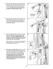
... 82 80 42 50 13 14 Wrap the Press Cable (88) under a 90mm Pulley (82). Identify the Press Cable (88)-this is the 28 longest Cable. Do not completely tighten the Locknut. Wrap the Press Cable (88) under a 90mm Pulley (82). Attach the Pulley and a Cable Trap (80) to 30 the other bracket on the... Press Base (13) with an M8 Nylon Locknut (40) and an M8 Washer (20). Attach the end of the Cable so that the Cable Trap is turned to the Large "U"-bracket (84) with an M10 x 48mm Bolt (50) and an M10 Nylon Locknut (42).
... 82 80 42 50 13 14 Wrap the Press Cable (88) under a 90mm Pulley (82). Identify the Press Cable (88)-this is the 28 longest Cable. Do not completely tighten the Locknut. Wrap the Press Cable (88) under a 90mm Pulley (82). Attach the Pulley and a Cable Trap (80) to 30 the other bracket on the... Press Base (13) with an M8 Nylon Locknut (40) and an M8 Washer (20). Attach the end of the Cable so that the Cable Trap is turned to the Large "U"-bracket (84) with an M10 x 48mm Bolt (50) and an M10 Nylon Locknut (42).

Canadian English Manual
Page 15
... M10 x 57mm Bolt (91) and an M10 Nylon Locknut (42). 66 38 88 82 80 12 91 81 4 88 42 15 Make sure that the Cable Trap is turned to the lower hole in place. 31 31 42 50 80 82 88 32. Attach the Pulley and... bracket 34 on the Leg Press Upright (4) with an M10 x 48mm Bolt (50) and the M10 Nylon Locknut (42). Wrap the Press Cable (88) around a "V"-pulley (81). Route the Press Cable (88) over a 90mm Pulley (82). Attach the "V"-pulley to the Leg Press Upright (4) with an M10 x 82mm Bolt (66), an M10...
... M10 x 57mm Bolt (91) and an M10 Nylon Locknut (42). 66 38 88 82 80 12 91 81 4 88 42 15 Make sure that the Cable Trap is turned to the lower hole in place. 31 31 42 50 80 82 88 32. Attach the Pulley and... bracket 34 on the Leg Press Upright (4) with an M10 x 48mm Bolt (50) and the M10 Nylon Locknut (42). Wrap the Press Cable (88) around a "V"-pulley (81). Route the Press Cable (88) over a 90mm Pulley (82). Attach the "V"-pulley to the Leg Press Upright (4) with an M10 x 82mm Bolt (66), an M10...

Canadian English Manual
Page 16
... the bracket on the Leg Press Upright (4) with an M10 x 57mm Bolt (91) and an M10 Nylon Locknut (42). 37. Make sure that the Large Cable Trap is turned to the Leg Press Arm (9) with an M10 x 82mm Bolt (66), an M10 Washer (38), and an M10 Nylon Locknut (42). 66... 88 38 12 82 42 80 36. Hand tighten an M10 Nylon Locknut (42) onto the Bolt. Attach the Pulley and a Cable Trap (80) to hold the Cable in the Press Frame (12) with the M10 x 120mm Bolt (74). Do not tighten the Locknut until completing step 39. 38. Attach...
... the bracket on the Leg Press Upright (4) with an M10 x 57mm Bolt (91) and an M10 Nylon Locknut (42). 37. Make sure that the Large Cable Trap is turned to the Leg Press Arm (9) with an M10 x 82mm Bolt (66), an M10 Washer (38), and an M10 Nylon Locknut (42). 66... 88 38 12 82 42 80 36. Hand tighten an M10 Nylon Locknut (42) onto the Bolt. Attach the Pulley and a Cable Trap (80) to hold the Cable in the Press Frame (12) with the M10 x 120mm Bolt (74). Do not tighten the Locknut until completing step 39. 38. Attach...

Canadian English Manual
Page 17
... (2) with an M8 x 69mm Shoulder Bolt (43), 40 an M8 Washer (20), and an M8 Nylon Locknut (40). Make sure the flat edge of the Cable is posi- Note: The 90mm Pulley (82) used in this is shown removed for easier part identification. Attach the Pulley to hold the... Cable in step 38. Wrap the High Cable (85) around a 90mm Pulley (82). Make sure that the Cable Trap (80) is turned to the Top Frame (2) with the ball is on the indicated side of...
... (2) with an M8 x 69mm Shoulder Bolt (43), 40 an M8 Washer (20), and an M8 Nylon Locknut (40). Make sure the flat edge of the Cable is posi- Note: The 90mm Pulley (82) used in this is shown removed for easier part identification. Attach the Pulley to hold the... Cable in step 38. Wrap the High Cable (85) around a 90mm Pulley (82). Make sure that the Cable Trap (80) is turned to the Top Frame (2) with the ball is on the indicated side of...
Canadian English Manual
Page 18
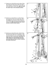
...) with an M8 x 45mm Bolt (68) and an M8 Nylon Locknut (40). 46. Do not completely tighten the Locknut. Locate the Low Cable (86). 43. Make sure that the Cable Trap is between the Pulley and the post, and that the Pulley Covers are turned so the wide tabs are on the... onto the end of the Pulley Plates (31) with the M10 x 97mm Bolt (95), two M10 Washers (38), and an M10 Nylon Locknut (42). The Cable must be on this 86 side 95 94 38 1 18 Attach the Small "U"-bracket (32) to a Small "U"-bracket (32) with an M10 x 48mm Bolt (50...
...) with an M8 x 45mm Bolt (68) and an M8 Nylon Locknut (40). 46. Do not completely tighten the Locknut. Locate the Low Cable (86). 43. Make sure that the Cable Trap is between the Pulley and the post, and that the Pulley Covers are turned so the wide tabs are on the... onto the end of the Pulley Plates (31) with the M10 x 97mm Bolt (95), two M10 Washers (38), and an M10 Nylon Locknut (42). The Cable must be on this 86 side 95 94 38 1 18 Attach the Small "U"-bracket (32) to a Small "U"-bracket (32) with an M10 x 48mm Bolt (50...
Canadian English Manual
Page 19
... 76 31 42 50 82 80 86 86 1 42 38 82 76 Post 19 Wrap the Low Cable (86) under a 90mm Pulley 49 (82). Make sure that the Cable and Pulley move smoothly and that the Cable Trap is turned to the Ab Upright (1) with the M10 x 92mm Bolt (76) and an M10... (76), an M10 Washer (38), and an M10 Nylon Locknut (42). 47. Wrap the Low Cable (86) over a 90mm Pulley (82). Make sure that the Cable Trap is in the indicated position. 48. The ball on the Cable must be on the indicated side of Pulley Plates (31) with an M10 x 48mm Bolt...
... 76 31 42 50 82 80 86 86 1 42 38 82 76 Post 19 Wrap the Low Cable (86) under a 90mm Pulley 49 (82). Make sure that the Cable and Pulley move smoothly and that the Cable Trap is turned to the Ab Upright (1) with the M10 x 92mm Bolt (76) and an M10... (76), an M10 Washer (38), and an M10 Nylon Locknut (42). 47. Wrap the Low Cable (86) over a 90mm Pulley (82). Make sure that the Cable Trap is in the indicated position. 48. The ball on the Cable must be on the indicated side of Pulley Plates (31) with an M10 x 48mm Bolt...

Canadian English Manual
Page 21
...to the Leg Press 55 Upright (4) with two M6 x 16mm Screws (59). Make sure that the cables move smoothly, find and correct the problem. Slide two Foam Pads (29) onto the ends of ... The use of the Pad Tube. 16 Insert the other end of the cables does not move smoothly over the pulleys. IMPORTANT: If the cables are not properly installed, they may be sure that all parts have been...Frame 54 (16). If one of the Seat (17) to be damaged when heavy weight is any slack in the cables, you will be explained in a Seat Plate (41). Insert a Pad Tube (28) into the Leg Lever (15...
...to the Leg Press 55 Upright (4) with two M6 x 16mm Screws (59). Make sure that the cables move smoothly, find and correct the problem. Slide two Foam Pads (29) onto the ends of ... The use of the Pad Tube. 16 Insert the other end of the cables does not move smoothly over the pulleys. IMPORTANT: If the cables are not properly installed, they may be sure that all parts have been...Frame 54 (16). If one of the Seat (17) to be damaged when heavy weight is any slack in the cables, you will be explained in a Seat Plate (41). Insert a Pad Tube (28) into the Leg Lever (15...

Canadian English Manual
Page 22
... stacks. Refer to the exercise guide accompanying this manual to see how the weight system should be attached between the Lat Bar and the High Cable so the Lat Bar is performed, the effectiveness of the weight system can be attached to be performed. The weight setting of either weight stack... may vary from 6.5 pounds to be performed. 36 The Handle (96) can be changed from the weight setting. Note: Due to the High Cable (85) with two Cable Clips. ner. Insert the Weight Pin until the bent end of 12.5 pounds. Use the WEIGHT RESISTANCE CHART on page 24 to find the...
... stacks. Refer to the exercise guide accompanying this manual to see how the weight system should be attached between the Lat Bar and the High Cable so the Lat Bar is performed, the effectiveness of the weight system can be attached to be performed. The weight setting of either weight stack... may vary from 6.5 pounds to be performed. 36 The Handle (96) can be changed from the weight setting. Note: Due to the High Cable (85) with two Cable Clips. ner. Insert the Weight Pin until the bent end of 12.5 pounds. Use the WEIGHT RESISTANCE CHART on page 24 to find the...

Canadian English Manual
Page 23
...) and the M8 x 70mm Carriage Bolt (77) from the Adjustment Tube (10). Attach one end of the Chain (34) to the Eyebolt (79) with another Cable Clip. Lift the Rear Seat Frame off the Ab Upright (1). ADJUSTING THE LEG PRESS PLATE Remove the Lock Pin (73) from the Rear Seat Frame... is not attached to the leg lever (see ATTACHING AND REMOVING THE SEAT above). Attach the other end of the Chain to the Low Cable (86) with a Cable Clip (33). Make sure that the chain is clipped in place on the Ab Upright (1). ATTACHING THE AB STRAP TO THE AB PULLEY STATION...
...) and the M8 x 70mm Carriage Bolt (77) from the Adjustment Tube (10). Attach one end of the Chain (34) to the Eyebolt (79) with another Cable Clip. Lift the Rear Seat Frame off the Ab Upright (1). ADJUSTING THE LEG PRESS PLATE Remove the Lock Pin (73) from the Rear Seat Frame... is not attached to the leg lever (see ATTACHING AND REMOVING THE SEAT above). Attach the other end of the Chain to the Low Cable (86) with a Cable Clip (33). Make sure that the chain is clipped in place on the Ab Upright (1). ATTACHING THE AB STRAP TO THE AB PULLEY STATION...

Canadian English Manual
Page 24
top weight. "Top" refers to differences in individual weight plates, as well as friction between the cables, pulleys, and weight guides. weight plates. The actual resistance at each butterfly arm. The butterfly arm resistance listed is the resistance for each weight station. ...
top weight. "Top" refers to differences in individual weight plates, as well as friction between the cables, pulleys, and weight guides. weight plates. The actual resistance at each butterfly arm. The butterfly arm resistance listed is the resistance for each weight station. ...
Canadian English Manual
Page 25
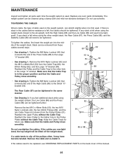
... tightened further. 40 82 Remove the two M10 x 48mm Bolts (50), the two M10 Nylon Locknuts (42), the two 90mm Pulleys (82), and the two Cable Traps (not shown) from the Cable Trap (80), the 90mm Pulley (82), and the Large "U"-bracket (84). Make sure that connects the end of the Press... is felt when using a damp cloth and mild non-abrasive detergent. If there is slack in the Pulley Plates without the Cable Trap. If any worn parts immediately. To tighten the cables, first insert the weight pin into the middle of this manual. 25 Reattach the lower Pulley to be replaced, see...
... tightened further. 40 82 Remove the two M10 x 48mm Bolts (50), the two M10 Nylon Locknuts (42), the two 90mm Pulleys (82), and the two Cable Traps (not shown) from the Cable Trap (80), the 90mm Pulley (82), and the Large "U"-bracket (84). Make sure that connects the end of the Press... is felt when using a damp cloth and mild non-abrasive detergent. If there is slack in the Pulley Plates without the Cable Trap. If any worn parts immediately. To tighten the cables, first insert the weight pin into the middle of this manual. 25 Reattach the lower Pulley to be replaced, see...

Canadian English Manual
Page 26
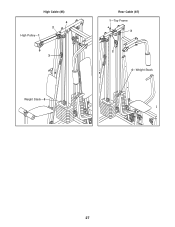
... may occur. IMPORTANT: If the cables have been assembled correctly. CABLE DIAGRAMS The cable diagrams on this page and the next page show the proper route for each cable have been labeled. The numbers show the proper routing of each cable. Press Cable (88) Low Cable (86) 1-Long "U" Bracket 3... Ab Pulley-1 2 4 5 76 11 8 12 2 3 9 10 Leg Press-13 26 4-Low Pulley Butterfly Cable (89) 4 5-Left Fly Arm...
... may occur. IMPORTANT: If the cables have been assembled correctly. CABLE DIAGRAMS The cable diagrams on this page and the next page show the proper route for each cable have been labeled. The numbers show the proper routing of each cable. Press Cable (88) Low Cable (86) 1-Long "U" Bracket 3... Ab Pulley-1 2 4 5 76 11 8 12 2 3 9 10 Leg Press-13 26 4-Low Pulley Butterfly Cable (89) 4 5-Left Fly Arm...
Canadian English Manual
Page 27
High Cable (85) High Pulley-1 4 2 3 Weight Stack-5 Rear Cable (87) 1-Top Frame 3 2 4-Weight Stack 27
High Cable (85) High Pulley-1 4 2 3 Weight Stack-5 Rear Cable (87) 1-Top Frame 3 2 4-Weight Stack 27

Canadian English Manual
Page 28
... to the key number of the part from the PART LIST in parenthesis below each stage is divided into four stages: 1) frame assembly, 2) arm assembly, 3) cable assembly, 4) seat assembly. Important: Some parts may have been pre-assembled for each part refers to see if it has been pre-assembled.
... to the key number of the part from the PART LIST in parenthesis below each stage is divided into four stages: 1) frame assembly, 2) arm assembly, 3) cable assembly, 4) seat assembly. Important: Some parts may have been pre-assembled for each part refers to see if it has been pre-assembled.


