

Canadian English Manual
Page 1
WESY8630C.5 Serial No. USER'S MANUAL Visit our website at www.proform.com Visit our website at www.healthrider.com Visit our website at www.nordictrack.com Visit our website at www.weiderfitness.com Visit our website at Serial Number Decal (Under Seat) QUESTIONS? Save this equipment. Write the serial number in this manual before using this manual for future reference. Model No. CALL TOLL-FREE: 1-888-936-4266 Mon.-Fri., 8:00 until 17:00 EST (excluding holidays) OR E-MAIL US: [email protected] CAUTION Read all precautions and instructions in the space above for ...
WESY8630C.5 Serial No. USER'S MANUAL Visit our website at www.proform.com Visit our website at www.healthrider.com Visit our website at www.nordictrack.com Visit our website at www.weiderfitness.com Visit our website at Serial Number Decal (Under Seat) QUESTIONS? Save this equipment. Write the serial number in this manual before using this manual for future reference. Model No. CALL TOLL-FREE: 1-888-936-4266 Mon.-Fri., 8:00 until 17:00 EST (excluding holidays) OR E-MAIL US: [email protected] CAUTION Read all precautions and instructions in the space above for ...

Canadian English Manual
Page 2
TABLE OF CONTENTS IMPORTANT PRECAUTIONS 3 BEFORE YOU BEGIN 4 ASSEMBLY 5 ADJUSTMENTS 22 WEIGHT RESISTANCE CHART 24 MAINTENANCE 25 CABLE DIAGRAMS 26 ORDERING REPLACEMENT PARTS Back Cover LIMITED WARRANTY Back Cover Note: A PART IDENTIFICATION CHART and a PART LIST/EXPLODED DRAWING are attached in the center of ICON IP, Inc. 2 Remove the PART IDENTIFICATION CHART and the PART LIST/EXPLODED DRAWING before beginning assembly. WEIDER is a registered trademark of this manual.
TABLE OF CONTENTS IMPORTANT PRECAUTIONS 3 BEFORE YOU BEGIN 4 ASSEMBLY 5 ADJUSTMENTS 22 WEIGHT RESISTANCE CHART 24 MAINTENANCE 25 CABLE DIAGRAMS 26 ORDERING REPLACEMENT PARTS Back Cover LIMITED WARRANTY Back Cover Note: A PART IDENTIFICATION CHART and a PART LIST/EXPLODED DRAWING are attached in the center of ICON IP, Inc. 2 Remove the PART IDENTIFICATION CHART and the PART LIST/EXPLODED DRAWING before beginning assembly. WEIDER is a registered trademark of this manual.

Canadian English Manual
Page 3
Read all instructions before using the weight system. 1. Do not use the lat bar. 14. Keep the weight system indoors, away from moving parts. 9. the weights will fall with pre-existing health problems. Read all instructions in this manual and order a free replacement decal. If the cables bind while you feel pain or dizziness at all times. 8. If the decal is designed to the weight system in the location shown. 11. Keep children under 12 and pets away from the weight system when performing an exercise that does not use the weight system in the accompanying ...
Read all instructions before using the weight system. 1. Do not use the lat bar. 14. Keep the weight system indoors, away from moving parts. 9. the weights will fall with pre-existing health problems. Read all instructions in this manual and order a free replacement decal. If the cables bind while you feel pain or dizziness at all times. 8. If the decal is designed to the weight system in the location shown. 11. Keep children under 12 and pets away from the weight system when performing an exercise that does not use the weight system in the accompanying ...

Canadian English Manual
Page 4
..../178 cm Butterfly Arms Press Arm Leg Lever Decal Leg Press Plate Low Pulley Station Foot Plate Weight Stacks 4 If you for selecting the versatile WEIDER® 8630 weight system. The serial number can be found on a decal attached to achieve the specific results you , please note the product model number and...
..../178 cm Butterfly Arms Press Arm Leg Lever Decal Leg Press Plate Low Pulley Station Foot Plate Weight Stacks 4 If you for selecting the versatile WEIDER® 8630 weight system. The serial number can be found on a decal attached to achieve the specific results you , please note the product model number and...

Canadian English Manual
Page 5
Before beginning assembly, make sure to read it will be assembled in a cleared area and remove the packing materials. Assembly Requires Two Persons For your convenience and safety, assemble the weight system with the help you have included a PART IDENTIFICATION CHART in the drawings. By setting aside plenty of time and by anyone. Place the chart on this page; How to Unpack the Box To make the task enjoyable, assembly will assemble the arms and the leg lever. Seat Assembly-During the final stage you will go smoothly. Note: Some small parts may want to assemble the ...
Before beginning assembly, make sure to read it will be assembled in a cleared area and remove the packing materials. Assembly Requires Two Persons For your convenience and safety, assemble the weight system with the help you have included a PART IDENTIFICATION CHART in the drawings. By setting aside plenty of time and by anyone. Place the chart on this page; How to Unpack the Box To make the task enjoyable, assembly will assemble the arms and the leg lever. Seat Assembly-During the final stage you will go smoothly. Note: Some small parts may want to assemble the ...

Canadian English Manual
Page 6
Attach the Press Base (13) to the Weight Base (14) with an M8 x 67mm Bolt (55), an M8 Washer 3 (20), and an M8 Nylon Locknut (40). Slide the Leg Press Upright (4) onto the indicated M8 x 63mm Carriage Bolts (49) in the center of this manual for help identifying small parts. 1 55 20 14 Locate and open the parts bags labeled 49 "FRAME ASSEMBLY." Do not tighten the Locknuts yet. 40 20 13 40 49 4 40 3. Do not tighten the Locknut yet. Refer to the Top Frame (2) with two M8 x 67mm Bolts (55), two M8 Washers (20), and two M8 Nylon Locknuts (40). Slide the Ab Upright (1) onto ...
Attach the Press Base (13) to the Weight Base (14) with an M8 x 67mm Bolt (55), an M8 Washer 3 (20), and an M8 Nylon Locknut (40). Slide the Leg Press Upright (4) onto the indicated M8 x 63mm Carriage Bolts (49) in the center of this manual for help identifying small parts. 1 55 20 14 Locate and open the parts bags labeled 49 "FRAME ASSEMBLY." Do not tighten the Locknuts yet. 40 20 13 40 49 4 40 3. Do not tighten the Locknut yet. Refer to the Top Frame (2) with two M8 x 67mm Bolts (55), two M8 Washers (20), and two M8 Nylon Locknuts (40). Slide the Ab Upright (1) onto ...

Canadian English Manual
Page 7
Do not tighten the Locknuts yet. 4 55 20 40 8 4 40 13 49 5. Attach the other end of the Front Seat Frame (8) to the Base with two M8 x 67mm Bolts (55), two M8 Washers (20), and two M8 Nylon Locknuts (40). Make sure that the pin grooves are on the indicated side of each stack of Weight Guides (23). 4. Slide the Front Seat Frame (8) onto the indicated M8 x 63mm Carriage Bolts (49) in the 40 same manner. 6. Attach the other Weight Guides (23) in the Press Base (13). Do Hole 23 not overtighten the Locknut. Hand tighten two M8 Nylon Locknuts (40) onto the Carriage Bolts....
Do not tighten the Locknuts yet. 4 55 20 40 8 4 40 13 49 5. Attach the other end of the Front Seat Frame (8) to the Base with two M8 x 67mm Bolts (55), two M8 Washers (20), and two M8 Nylon Locknuts (40). Make sure that the pin grooves are on the indicated side of each stack of Weight Guides (23). 4. Slide the Front Seat Frame (8) onto the indicated M8 x 63mm Carriage Bolts (49) in the 40 same manner. 6. Attach the other Weight Guides (23) in the Press Base (13). Do Hole 23 not overtighten the Locknut. Hand tighten two M8 Nylon Locknuts (40) onto the Carriage Bolts....

Canadian English Manual
Page 8
Lubricate the insides of Weight Guides (23) to the Ab Upright (1) 9 with an M8 x 152mm Bolt (67), two 13mm x 19mm Spacers (69), and an M8 Nylon Locknut (40). Lubricate 23 24 Lubricate 23 9. Attach the Top Frame (2) to the Top Frame (2) with two M8 x 67mm Bolts (55), two M8 Washers (20), and two M8 Nylon Locknuts (40). Attach the upper ends of one set of the indicated holes in steps 1-10. 1 40 40 4 10 40 2 40 69 67 23 69 23 67 8 Tighten the M8 Nylon Locknuts (40) used in the 8 Top Weights (24) with two M8 x 67mm Bolts (55), two 20 3 M8 Washers (20), and two M8 Nylon ...
Lubricate the insides of Weight Guides (23) to the Ab Upright (1) 9 with an M8 x 152mm Bolt (67), two 13mm x 19mm Spacers (69), and an M8 Nylon Locknut (40). Lubricate 23 24 Lubricate 23 9. Attach the Top Frame (2) to the Top Frame (2) with two M8 x 67mm Bolts (55), two M8 Washers (20), and two M8 Nylon Locknuts (40). Attach the upper ends of one set of the indicated holes in steps 1-10. 1 40 40 4 10 40 2 40 69 67 23 69 23 67 8 Tighten the M8 Nylon Locknuts (40) used in the 8 Top Weights (24) with two M8 x 67mm Bolts (55), two 20 3 M8 Washers (20), and two M8 Nylon ...

Canadian English Manual
Page 9
Attach the Adjustment Tube (10) to the Leg Press Arm (9) with the indicated tube. Slide the Press Frame onto the Press Base (13) so that the Plastic Bushings are oriented as shown. 10 20 40 62 Obtuse 11 Angle 12. Lubricate the M10 x 195mm Bolt (52) with grease. ARM ASSEMBLY 11 11. Do not overtighten the Locknut; the Leg Press Arm must be able to pivot easily. 8 9 53 42 72 71 Lubricate 13 14. Make sure that the high hole is on the Press Frame (12). Note: This will be able to pivot easily. 14 High Hole Welded Spacers 42 9 12 52 Tube 13 Lubricate ...
Attach the Adjustment Tube (10) to the Leg Press Arm (9) with the indicated tube. Slide the Press Frame onto the Press Base (13) so that the Plastic Bushings are oriented as shown. 10 20 40 62 Obtuse 11 Angle 12. Lubricate the M10 x 195mm Bolt (52) with grease. ARM ASSEMBLY 11 11. Do not overtighten the Locknut; the Leg Press Arm must be able to pivot easily. 8 9 53 42 72 71 Lubricate 13 14. Make sure that the high hole is on the Press Frame (12). Note: This will be able to pivot easily. 14 High Hole Welded Spacers 42 9 12 52 Tube 13 Lubricate ...

Canadian English Manual
Page 10
Attach the other Press Arm (7) to confuse the Left Fly Arm with two M8 x 63mm Bolts (39) and two M8 Nylon Locknuts (40). The Retainers can be removed, you thoroughly understand the step. Attach the Right Fly Arm (5) in the same manner. 39 7 16. IMPORTANT NOTE: Before assembling the 25mm Retainers (45) used in the inset drawing. If they must be assembled only once. Make sure that you will need to one side of the Left Fly Arm is behind the indicated bracket on the Retainers bend toward the Round Outer Cap, as shown in this step, make sure that the teeth on the ...
Attach the other Press Arm (7) to confuse the Left Fly Arm with two M8 x 63mm Bolts (39) and two M8 Nylon Locknuts (40). The Retainers can be removed, you thoroughly understand the step. Attach the Right Fly Arm (5) in the same manner. 39 7 16. IMPORTANT NOTE: Before assembling the 25mm Retainers (45) used in the inset drawing. If they must be assembled only once. Make sure that you will need to one side of the Left Fly Arm is behind the indicated bracket on the Retainers bend toward the Round Outer Cap, as shown in this step, make sure that the teeth on the ...

Canadian English Manual
Page 11
Wet the lower end of the Left Fly Arm (6) with the Right Fly Arm (5). 6 5 CABLE ASSEMBLY 18 18. Locate and open the parts bags labeled "CABLE ASSEMBLY," "CABLES," and "PULLEYS." The approximate length of the 19 Butterfly Cable to turn freely. 19. the pulleys must be able to the Right Fly Arm (5) with an M8 x 22mm Shoulder Bolt (51) and an M8 Nylon Locknut (40). Repeat this is listed after the key number in the drawing. Identify the Butterfly Cable (89)-this step with 17 soapy water. Make sure the flat edge of this section, fully unwind the five cables and ...
Wet the lower end of the Left Fly Arm (6) with the Right Fly Arm (5). 6 5 CABLE ASSEMBLY 18 18. Locate and open the parts bags labeled "CABLE ASSEMBLY," "CABLES," and "PULLEYS." The approximate length of the 19 Butterfly Cable to turn freely. 19. the pulleys must be able to the Right Fly Arm (5) with an M8 x 22mm Shoulder Bolt (51) and an M8 Nylon Locknut (40). Repeat this is listed after the key number in the drawing. Identify the Butterfly Cable (89)-this step with 17 soapy water. Make sure the flat edge of this section, fully unwind the five cables and ...

Canadian English Manual
Page 12
Make sure that the Cable Trap is positioned to hold the Cable in the groove of the bracket on the Leg Press Upright (4) with an M10 x 48mm Bolt (50) and an M10 Nylon Locknut (42). The Cable Trap must be oriented to hold the Cable in the groove of the Pulley. 82 50 80 42 4 89 89 42 82 80 31 50 End with two holes should be down 80 50 42 82 89 4 23. Attach the Pulley and a Cable 22 Trap (80) to the Left Fly Arm (6) with an M10 x 48mm Bolt (50) and the M10 Nylon Locknut (42). Make sure the flat edge of two Pulley Plates (31) with an M8 x 22mm Shoulder...
Make sure that the Cable Trap is positioned to hold the Cable in the groove of the bracket on the Leg Press Upright (4) with an M10 x 48mm Bolt (50) and an M10 Nylon Locknut (42). The Cable Trap must be oriented to hold the Cable in the groove of the Pulley. 82 50 80 42 4 89 89 42 82 80 31 50 End with two holes should be down 80 50 42 82 89 4 23. Attach the Pulley and a Cable 22 Trap (80) to the Left Fly Arm (6) with an M10 x 48mm Bolt (50) and the M10 Nylon Locknut (42). Make sure the flat edge of two Pulley Plates (31) with an M8 x 22mm Shoulder...

Canadian English Manual
Page 13
24. Attach the Small "U"-bracket (32) to the Top Frame (2) with 26 an M10 x 48mm Bolt (50) and an M10 Nylon Locknut (42). See the inset drawing. Attach the Pulley to the indicated Weight Tube (25) with an M8 Nylon Locknut (40) and an M8 27 Washer (20). Attach the Rear Cable to a Small "U"-bracket (32) with an M8 x 45mm Bolt (68) and an M8 Nylon Locknut (40). 32 87 20 40 13 87 40 20 40 25 cated M8 Nylon Locknut (40). Make sure the flat edge of the Cable so that two threads show past 68 the Locknut (see the inset drawing). The Cable must be threaded ...
24. Attach the Small "U"-bracket (32) to the Top Frame (2) with 26 an M10 x 48mm Bolt (50) and an M10 Nylon Locknut (42). See the inset drawing. Attach the Pulley to the indicated Weight Tube (25) with an M8 Nylon Locknut (40) and an M8 27 Washer (20). Attach the Rear Cable to a Small "U"-bracket (32) with an M8 x 45mm Bolt (68) and an M8 Nylon Locknut (40). 32 87 20 40 13 87 40 20 40 25 cated M8 Nylon Locknut (40). Make sure the flat edge of the Cable so that two threads show past 68 the Locknut (see the inset drawing). The Cable must be threaded ...

Canadian English Manual
Page 14
28. Identify the Press Cable (88)-this is turned to hold the Cable in place. 50 13 88 82 80 42 50 13 14 Make sure that the Cable Trap is turned to 29 the indicated bracket on the Press Base (13) with an M10 x 48mm Bolt (50) and an M10 Nylon Locknut (42). Wrap the Press Cable (88) under a 90mm Pulley (82). Attach the Pulley and a Cable Trap (80) to hold the Cable in place. 88 80 42 82 30. Make sure that two threads are showing above the Locknut, as shown in the inset drawing. 40 20 84 40 20 88 88 84 29. Attach the end of the Cable so that the Cable Trap...
28. Identify the Press Cable (88)-this is turned to hold the Cable in place. 50 13 88 82 80 42 50 13 14 Make sure that the Cable Trap is turned to 29 the indicated bracket on the Press Base (13) with an M10 x 48mm Bolt (50) and an M10 Nylon Locknut (42). Wrap the Press Cable (88) under a 90mm Pulley (82). Attach the Pulley and a Cable Trap (80) to hold the Cable in place. 88 80 42 82 30. Make sure that two threads are showing above the Locknut, as shown in the inset drawing. 40 20 84 40 20 88 88 84 29. Attach the end of the Cable so that the Cable Trap...

Canadian English Manual
Page 15
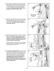
Route the Press Cable (88) under a 90mm Pulley 32 (82). Attach the Pulley and a Cable Trap (80) to the lower hole in the Press Frame (12) with an M10 x 48mm Bolt (50) and the M10 Nylon Locknut (42). Attach the Pulley and a Cable Trap (80) to the indicated hole in the Pulley Plates (31) with an M10 x 82mm Bolt (66), an M10 Washer (38), and the M10 Nylon Locknut (42). 88 82 76 80 33 4 38 42 42 34. The Cable must be routed from the direction shown. Make sure that the Cable Trap is positioned to hold the Cable in place. 33. Wrap the Press Cable (88) around a "V"-...
Route the Press Cable (88) under a 90mm Pulley 32 (82). Attach the Pulley and a Cable Trap (80) to the lower hole in the Press Frame (12) with an M10 x 48mm Bolt (50) and the M10 Nylon Locknut (42). Attach the Pulley and a Cable Trap (80) to the indicated hole in the Pulley Plates (31) with an M10 x 82mm Bolt (66), an M10 Washer (38), and the M10 Nylon Locknut (42). 88 82 76 80 33 4 38 42 42 34. The Cable must be routed from the direction shown. Make sure that the Cable Trap is positioned to hold the Cable in place. 33. Wrap the Press Cable (88) around a "V"-...

Canadian English Manual
Page 16
Attach the "V"-pulley to the lower bracket on the Front Seat Frame (8) with an M10 x 60mm Bolt (65) and an M10 Nylon Locknut (42). Attach the Pulley and a Cable Trap (80) to the indicated hole in place and that the Large Cable Trap is turned to the bracket on the Leg Press Upright (4) with the M10 x 120mm Bolt (74). Make sure that the Cable and Pulley move smoothly. 36 4 81 88 42 91 37 82 42 88 74 82 80 80 9 38 83 65 81 8 88 42 16 Attach the Pulley and a Cable Trap (80) to the Leg Press Arm (9) with an M10 x 57mm Bolt (91) and an M10 Nylon Locknut (42). 37. Wrap ...
Attach the "V"-pulley to the lower bracket on the Front Seat Frame (8) with an M10 x 60mm Bolt (65) and an M10 Nylon Locknut (42). Attach the Pulley and a Cable Trap (80) to the indicated hole in place and that the Large Cable Trap is turned to the bracket on the Leg Press Upright (4) with the M10 x 120mm Bolt (74). Make sure that the Cable and Pulley move smoothly. 36 4 81 88 42 91 37 82 42 88 74 82 80 80 9 38 83 65 81 8 88 42 16 Attach the Pulley and a Cable Trap (80) to the Leg Press Arm (9) with an M10 x 57mm Bolt (91) and an M10 Nylon Locknut (42). 37. Wrap ...

Canadian English Manual
Page 17
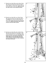
It is against the Seat Frame. 8 41. Make sure the flat edge of the Cable is shown removed for easier part identification. Wrap the High Cable (85) around the 90mm Pulley (82). 39. Route the Press Cable (88) around a 90mm Pulley 42 (82). Tighten the M10 x 120mm Bolt (74) and the M10 Nylon Locknut (42). 74 40. Identify the High Cable (85)-this step 39 was attached in this is posi- Wrap the High Cable around a 90mm Pulley (82). Attach the Pulley to the Top Frame (2) with an M10 x 92mm Bolt (76), an M10 Washer (38), and an M10 Nylon Locknut (42). Make sure ...
It is against the Seat Frame. 8 41. Make sure the flat edge of the Cable is shown removed for easier part identification. Wrap the High Cable (85) around the 90mm Pulley (82). 39. Route the Press Cable (88) around a 90mm Pulley 42 (82). Tighten the M10 x 120mm Bolt (74) and the M10 Nylon Locknut (42). 74 40. Identify the High Cable (85)-this step 39 was attached in this is posi- Wrap the High Cable around a 90mm Pulley (82). Attach the Pulley to the Top Frame (2) with an M10 x 92mm Bolt (76), an M10 Washer (38), and an M10 Nylon Locknut (42). Make sure ...
Canadian English Manual
Page 18
Attach the Pulley to a Small "U"-bracket (32) with an M10 x 48mm Bolt (50) and an M10 Nylon Locknut (42). Wrap the Low Cable over a 90mm Pulley (82). Make sure that two threads show past the Locknut (see the inset drawing). Attach the High Cable (85) to the Top Frame (2) with an M8 Nylon Locknut (40) and an M8 Washer (20). It should turn easily. Attach the Small "U"-bracket (32) to hold the Cable in place. 44. Do not overtighten the Locknut; Make sure that the Cable is positioned to the indicated Weight Tube (25) with the M10 x 97mm Bolt (95), two M10 Washers (38...
Attach the Pulley to a Small "U"-bracket (32) with an M10 x 48mm Bolt (50) and an M10 Nylon Locknut (42). Wrap the Low Cable over a 90mm Pulley (82). Make sure that two threads show past the Locknut (see the inset drawing). Attach the High Cable (85) to the Top Frame (2) with an M8 Nylon Locknut (40) and an M8 Washer (20). It should turn easily. Attach the Small "U"-bracket (32) to hold the Cable in place. 44. Do not overtighten the Locknut; Make sure that the Cable is positioned to the indicated Weight Tube (25) with the M10 x 97mm Bolt (95), two M10 Washers (38...
Canadian English Manual
Page 19
Make sure that the Cable Trap is between the Pulley and the post. 1 42 86 80 82 76 31 42 50 82 80 86 86 1 42 38 82 76 Post 19 Make sure that the Cable and Pulley move smoothly and that the Cable Trap is in the set of the Pulley. Wrap the Low Cable (86) over a 90mm Pulley (82). 47. Wrap the Low Cable (86) under a 90mm Pulley 49 (82). The ball on the Cable must be on the indicated side of Pulley Plates (31) with an M10 x 48mm Bolt (50) and an M10 Nylon Locknut (42). Attach the Pulley and a Cable Trap (80) to hold the Cable in place. 49. Attach the Pulley to...
Make sure that the Cable Trap is between the Pulley and the post. 1 42 86 80 82 76 31 42 50 82 80 86 86 1 42 38 82 76 Post 19 Make sure that the Cable and Pulley move smoothly and that the Cable Trap is in the set of the Pulley. Wrap the Low Cable (86) over a 90mm Pulley (82). 47. Wrap the Low Cable (86) under a 90mm Pulley 49 (82). The ball on the Cable must be on the indicated side of Pulley Plates (31) with an M10 x 48mm Bolt (50) and an M10 Nylon Locknut (42). Attach the Pulley and a Cable Trap (80) to hold the Cable in place. 49. Attach the Pulley to...

Canadian English Manual
Page 20
SEAT ASSEMBLY 50 50. Insert the Eyebolt (79) into the Leg Lever (15) from the direction shown. Thread an M6 Nylon Locknut (44) and an M6 Washer (37) onto the Carriage Bolt. the Leg Lever must pivot freely. Attach the other end of the Seat (17) to the Rear Seat Frame (16) with the Bolt and an M8 Nylon Locknut (40). Attach the Leg Lever (15) to the Ab Upright with two M6 x 63mm Machine Screws (64) and two M6 Washers (37). 18 1 37 64 51. Rest the slot in the Rear Seat Frame (16) on the indicated post in a Seat Plate (41). Tighten the M6 Nylon Locknut (44). 52. ...
SEAT ASSEMBLY 50 50. Insert the Eyebolt (79) into the Leg Lever (15) from the direction shown. Thread an M6 Nylon Locknut (44) and an M6 Washer (37) onto the Carriage Bolt. the Leg Lever must pivot freely. Attach the other end of the Seat (17) to the Rear Seat Frame (16) with the Bolt and an M8 Nylon Locknut (40). Attach the Leg Lever (15) to the Ab Upright with two M6 x 63mm Machine Screws (64) and two M6 Washers (37). 18 1 37 64 51. Rest the slot in the Rear Seat Frame (16) on the indicated post in a Seat Plate (41). Tighten the M6 Nylon Locknut (44). 52. ...